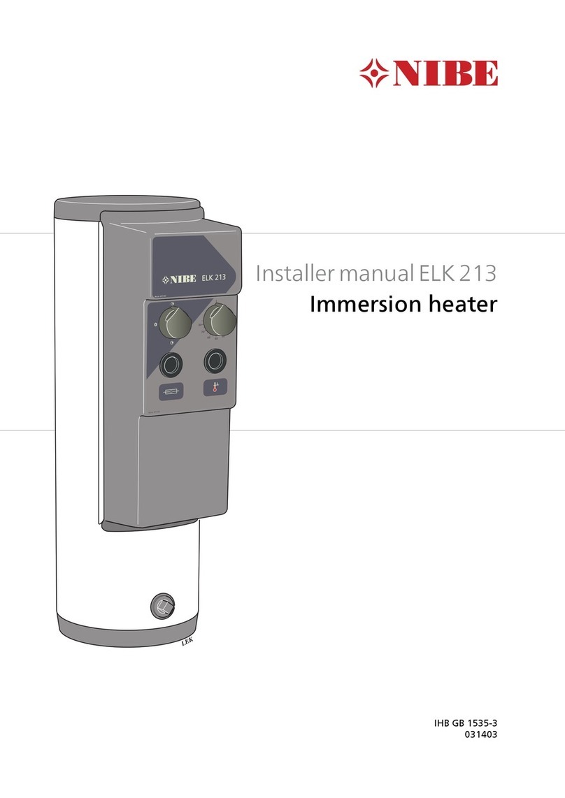
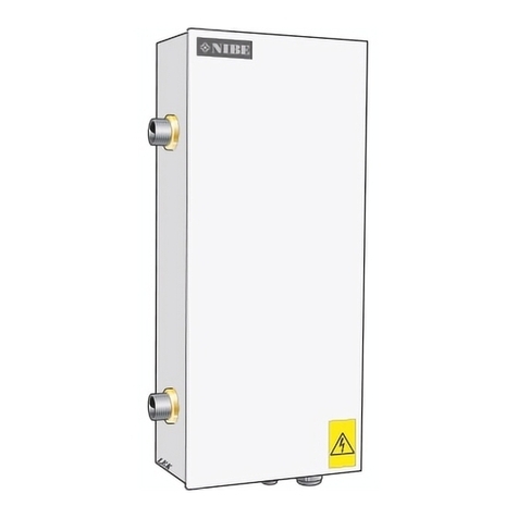
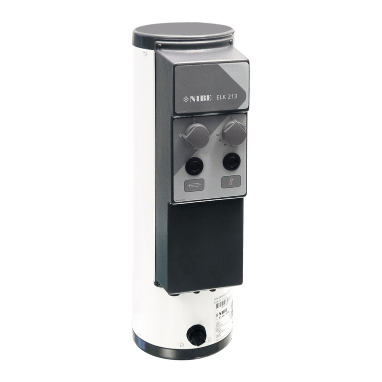
Nibe ELK 213 User guide

IHB EN 2036-8
031403
INSTALLER MANUAL - ELECTRIC HEATER
Immersion heater
NIBE ELK 213
LEK


41 Important information
4Safety information
4Symbols
4Marking
4Serial number
4Recovery
52 General
5Compatible products
5Contents
5Assembly
6Component positions
7Front panel
83 Pipe connections
8General
8Pressure drop diagram ELK 213
9System diagram
9Installation alternative
104 Electrical connection
10Electrical connection versions F1345
10F1345 2.0 / F1355
11F1345
11SMO S40
11SMO 20 and SMO 40
11S1155, S1255, VVM S320, VVM S325
12
F1145, F1155, F1245, F1255, VVM 225, VVM 310,
VVM 320, VVM 325 and VVM 500
12Power supply
12Output
13Time relay
13Sensors
13Connection of the circulation pump (GP10)
145 Program settings
14Menu system
166 Disturbances in comfort
16Troubleshooting
177 Technical data
17Dimensions
18Technical specifications
18Energy labelling
19Electrical circuit diagram
20Item register
23Contact information
3Table of ContentsNIBE ELK 213
Table of Contents

Safety information
This manual describes installation and service proced-
ures for implementation by specialists.
The manual must be left with the customer.
This appliance can be used by children
aged from 8 years and above and persons
with reduced physical, sensory or mental
capabilities or lack of experience and
knowledge if they have been given super-
vision or instruction concerning use of the
appliance in a safe way and understand
the hazards involved. Children shall not
play with the appliance. Cleaning and user
maintenance shall not be made by children
without supervision.
Rights to make any design or technical
modifications are reserved.
©NIBE 2020.
Symbols
NOTE
This symbol indicates danger to person or ma-
chine .
Caution
This symbol indicates important information
about what you should consider when installing
or servicing the installation.
TIP
This symbol indicates tips on how to facilitate
using the product.
Marking
The CE mark is obligatory for most products sold
in the EU, regardless of where they are made.
CE
Classification of enclosure of electro-technical
equipment.
IP21
Danger to person or machine.
!
Read the Installer Manual.
Serial number
The serial number can be found on the type plate on the
side of ELK 213.
Caution
You need the product's (14 digit) serial number
for servicing and support.
Recovery
Leave the disposal of the packaging to the in-
staller who installed the product or to special
waste stations.
Do not dispose of used products with normal
household waste. It must be disposed of at a
special waste station or dealer who provides this type
of service.
Improper disposal of the product by the user results in
administrative penalties in accordance with current le-
gislation.
NIBE ELK 213Chapter 1 | Important information4
1 Important information

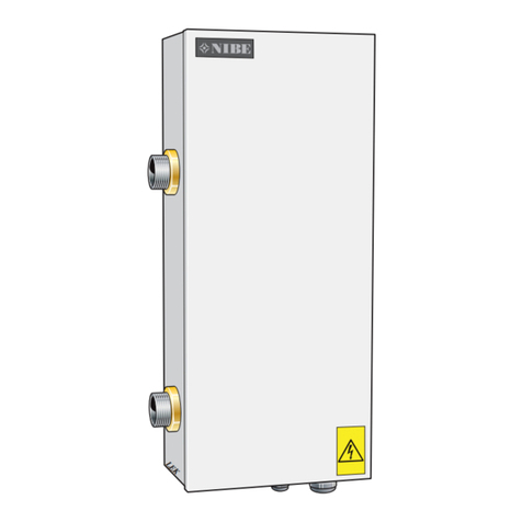
ELK 213 is an electric heater intended for heating
buildings and indirect heating of hot water. ELK 213 can
also be mounted together with a boiler, accumulator
tank or heat pump. When installing together with a heat
pump, for example, the electric heater is engaged
automatically as supplementary heating when the
heating demand is greater than the heat pump’s capa-
city.
The stainless steel electric coils and electric boiler tube
are made of acid-resistant steel (SIS 2333), which gives
a very good service life.
ELK 213 contains temperature limiter and contactors to
enable external control of the power.
ELK 213 is equipped with a time relay. Time delay is
recommended when the connected power exceeds 6
kW. The thermostats for the immersion heater and
isolator switch are operated by knobs on the control
panel.
Compatible products
Connection is different depending on which product
ELK 213 is to be used with.
These products can be connected directly to ELK 213:
• SMO 20
• SMO 40
• F1345
• F1355
These products require the accessory AXC 40:
S-series
• VVM S320
• VVM S325
• S1155
• S1255
• SMO S40
F-series
• VVM 225
• VVM 320
• VVM 325
• F1145
• F1155
• F1245
• F1255
VVM 310 requires the accessory DEH 310 .
VVM 500 requires the accessory DEH 500.
Contents
Immersion heater1 x
Assembly
The electric heater must be installed upright (see image
below).
A free space of 800 mm in front of the water heater and
500 mm above is required to carry out servicing. If this
is not possible, detachable connections must be used.
800
500
5Chapter 2 | GeneralNIBE ELK 213
2 General

Component positions
123456789NI
N1
N2
L1
L2
L3
QA3
QA2QA1
X8
KF1
X1
SF1
FC1
BT35
FQ10
XL1
XL2
EB1
PZ3
XL10
*
Component list
Immersion heaterEB1
Thermostat 3-poleBT35
Miniature circuit-breakerFC1
Temperature limiterFQ10
Time relayKF1
Serial number platePZ3
Contactor (-K10)QA1
Contactor (-K22)QA2
Contactor (-K21)QA3
SwitchSF1
Terminal blockX1
Terminal blockX8
Connection supply line, R50XL1
Connection return line, R50XL2
Drain connection R20XL10
* Counter flanges, R50. Accessory needed. See section "Accumulator tank (SP 300)" on page 9for more information.
Designations according to standard EN 81346-2.
NIBE ELK 213Chapter 2 | General6

Front panel
SF1
FC1
BT35
FQ10-S2
NOTE
The switch (SF1) must not be put in "
D
a
y
15
12
24
21
618
R
3
9
15
ON OF F
" mode
until the boiler has been filled with water.
Otherwise, the temperature limiter, the ther-
mostat and the immersion heater may be
damaged.
Functions on the front panel
SwitchSF1
with 3 positions 0 -
D
a
y
15
12
24
21
618
R
3
9
15
ON OF F
-
D
a
y
15
12
24
21
618
R
3
9
15
ON OF F
:
Electric heater off (immersion heater and
any connected devices not in operation).
0
Any circulation pump in operation.
D
a
y
15
12
24
21
618
R
3
9
15
ON OF F
Immersion heater operating (immersion
heater and any connected devices in oper-
ation).
D
a
y
15
12
24
21
618
R
3
9
15
ON OF F
Immersion heater thermostatBT35
This thermostat controls the immersion heat-
ers.
Miniature circuit-breakerFC1
Reset a tripped miniature circuit breaker by
pushing the button.
Temperature limiterFQ10-S2
Reset a tripped temperature limiter by pressing
the button. Only do this once the cause of the
fault has been rectified, see section
"Troubleshooting" on page 16.
7Chapter 2 | GeneralNIBE ELK 213

General
The pipe installation must be carried out in accordance
with applicable standards.
A circulation pump must be used to ensure the flow
over the immersion heater. If the heating system valves
can close the circulation completely, the bypass valve
must be installed so that the flow through the electric
heater does not stop. In closed installations an approved
safety valve and pressure expansion vessel must be
used.
Caution
Also see the installer manual for your heat
pump/indoor module.
NOTE
The pipe work must be flushed before the
electric heater is connected, so that any con-
taminants do not damage the component parts.
DRAINING
If a drain valve is necessary, it can be installed in the
water heater's drain connection XL10). This connection
can also be used as a circulation pump connection. The
connection is plugged upon delivery.
SAFETY VALVE
In closed boiler installations, the safety valves must be
installed in connection with the highest part of the
electric heater, but not directly on the heater. The con-
nection line must rise continuously.
The safety valve must be "exercised" regularly, at least
four times a year.
NOTE
The pipe work must be flushed before the
electric heater is connected, so that any con-
taminants do not damage the component parts.
Pressure drop diagram
ELK 213
Flow
(kPa)
00 0,1 0,2 0,4 (l/s)
0,5
1
1,5
2
(kPa)
0,3 0,5 0,6
(l/s)
NIBE ELK 213Chapter 3 | Pipe connections8
3 Pipe connections

System diagram
NOTE
This is the outline diagram. Actual installations
must be planned according to applicable
standards.
SYMBOL KEY
MeaningSymbol
Shut-off valve
Non-return valve
Mixing valve
Circulation pump
Expansion vessel
Pressure gauge
Safety valve
Temperature sensor
Trim valve
Reversing valve/shunt
Heat pump
Radiator system
Domestic hot water
Hot water circulation
Designations according to standard EN 81346-2.
OUTLINE DIAGRAM
ELK 213
P
As a freestanding electric boiler
ELK 213
P
Installation alternative
ACCUMULATOR TANK (SP 300)
For installing ELK 213 to SP 300 accessory "Thread
flange kit" is required (Part no. 022 077).
In the event of large hot water demands, ELK 213, in-
stalled on double-jacket accumulator tank type, can be
used to heat the domestic hot water. This is also a good
solution for aggressive or hard water.
Recommended thermostat setting: 75 °C
ELK 213
BOILER WITH INTERNAL WATER HEATER
With the immersion heater installed on an existing boiler,
the existing control equipment is used.
Install the electric heater so that external heating does
not cause overheating, for example, in front of the fire-
box door (to prevent flames blowing out) or next to the
flue pipe (to prevent damaging heat radiation). A suitable
location is normally at the side of the boiler, directly on
the double jacketed heater’s flanges or similar location.
When the electric heater is installed on the existing
wood boiler and is solely responsible for the heating
demand, the flue should be sealed.
P
9Chapter 3 | Pipe connectionsNIBE ELK 213

NOTE
All electrical connections must be carried out
by an authorised electrician.
Electrical installation and wiring must be carried
out in accordance with the stipulations in force.
The climate unit must not be powered when
installing ELK 213.
ELK 213 must be installed on terminal block X1 via a
circuit breaker with a minimum breaking gap of 3 mm.
The electrical circuit diagram is at the end of this Installer
handbook.
Electrical connection
versions F1345
F1345 has different electrical connection versions de-
pending on when the heat pump was manufactured. To
check which electrical connection applies to your F1345,
check the designation "2.0" visible above the right hand
side of the terminal block as illustrated.
LEK
If ELK 213 is to be controlled externally, the straps
between X8:1-X8:6, X8:2-X8:7 and X1:N1-X1:N2 must
be removed. In addition, the strap between X8:3-X8:5
must be moved so that it runs between X8:3-X8:9.
F1345 2.0 / F1355
Terminal blocks X1 and X8 in ELK 213 connect to the
terminal blocks X5, X7 and X8 on the input board AA101
in the heat pump as illustrated.
X5 X7 X8
L1
-X3 -X4
123
-AA101 -AA101
NL2 L3 1 2 3456789
-X5 1 2 3456789
-X6
-X7 -X8 -X9
-FC1
-AA101 -AA101
-AA101 -AA101 -AA101
1 2 341 2 31 2 31 2 345
-X10
A B A B
-AA3-X7
K1
-AA101
K2 K3
C C NO NC
K4 CNO NC
QN10 GP16
LNL L L N N N LNLNPE
PE
6789 10 11 12 13 14 15 16 17 18 19 20 2122
12V
A B 13 14
-BE1
-GP16
-BE2
-BE3
AUX 4
AUX 5
1 2 3456789 10 11 12 13 14 15
-AA3
-X6
0-10V -EP14 -EP15
-BF1
16 17 18 2
-AA3
-X22 -AA3
-AA3
-X20 -X21 13123
-X23
-BT1
-BT50
-BT25
-BT6
AUX 1
AUX 2
AUX 3
-BT7
-BT71
2.0
L2 L3N2 L1
N1 PE 1 2 3 4 5 6 7 8 9 N
X8
X1
Värmepump
ELK 213
1 2 3 4 5 6 1 2 3 4 1 2 3
X5 X8X7
Heat pump
ELK213
NIBE ELK 213Chapter 4 | Electrical connection10
4 Electrical connection

F1345
Terminal blocks X1 and X8 in ELK 213 connect to the
terminal blocks X2-X4 in the heat pump as illustrated.
X2 X3 X4
L2 L3N2 L1
N1 PE
1 2 3 4 5 6 1 2 31 2 3 4 5 6 7 8 9
1 2 3 4 5 6 7 8 9 N
X8
X1
X2 X4X3
Värmepump
ELK 213
ELK213
Heat pump
SMO S40
For connecting ELK 213 to SMO S40.
Terminal blocks X1 and X8 in ELK 213 connect to termin-
al blocks AA100-X3 and AA100-X8 in SMO S40 as illus-
trated.
Terminal block AA100-X4 connect to terminal block
AA100-X8 as illustrated.
L2 L3N2 L1N1 PE 1 2 3 4 5 6 7 8 9 N
1 2 3C
X8X1
Styrmodul
ELK 213
L L L L
N N N N N NN
AA100-X3
AA100-X4
AA100-X8
ELK213
Control module
SMO 20 and SMO 40
For connecting ELK 213 to SMO 20 and SMO 40.
Terminal blocks X1 and X8 in ELK 213 connect to termin-
al blocks X1 and AA7-X2 in SMO 20 and SMO 40 as il-
lustrated.
L2 L3N2 L1N1 PE
1 0 PE 2 3 4
1 2 3 4 5 6 7 8 9 N
X8X1
X1
Styrmodul
ELK 213
AA7:X2
1 2 3 4 5 6
Control
module
ELK213
S1155, S1255,
VVM S320, VVM S325
For connecting ELK 213 via accessory board AXC 40.
Terminal blocks X1 and X8 in ELK 213 connect to termin-
al block AA5-X9 in AXC 40 as illustrated.
L2 L3N2 L1N1 PE
1 2 3 4 5 6 7 8
1 2 3 4 5 6 7 8 9 N
X8X1
Tillbehörskort
ELK 213
AA5-X9
Accessory card
ELK213
11Chapter 4 | Electrical connectionNIBE ELK 213

F1145, F1155, F1245,
F1255, VVM 225,
VVM 310, VVM 320,
VVM 325 and
VVM 500
For connecting ELK 213 via accessory board AXC 40.
Terminal blocks X1 and X8 in ELK 213 connect to termin-
al block AA5-X9 in AXC 40 as illustrated.
L2 L3N2 L1N1 PE
1 2 3 4 5 6 7 8
1 2 3 4 5 6 7 8 9 N
X8X1
Tillbehörskort
ELK 213
AA5-X9
Accessory card
ELK213
Power supply
The power cable must be selected for the relevant
power and connected to terminal block X1.
Upon delivery the electric heater has three unopened
cable grommets. These are for supply, external control,
circulation pump and load monitor.
Output
The immersion heater can be set up to a maximum of
13 kW. The delivery setting is 9 kW in two steps.
The immersion heater’s power output is divided into
steps, 7, 9, 11 and 13 kW. Switching to another power
output is performed at the top of the electric water
heater, directly on the immersion heater’s connections
and on terminal block (X8) in the electrical connection.
The power output can be controlled in three steps in all
powers and in two steps for power outputs 7 and 9 kW.
Powers 11 and 13 kW must not be controlled in two
steps. Change-over occurs on terminal block (X8) using
the wiring enclosed.
9 kW in two steps (delivery setting)
1 2 3 4 5 6 7 8 9 N
X8
7/9 kW in three steps
1 2 3 4 5 6 7 8 9 N
X8
11/13 kW in three steps
1 2 3 4 5 6 7 8 9 N
X8
CONTROLLING THE IMMERSION HEATER
NOTE
It is recommended that ELK 213 is linearly
controlled. If binary control is still required, en-
sure that step one has lowest output, step two
next highest output and step three the highest
output.
Power step (kW)Set output (kW)
1, 2, 47
2, 3, 49
1, 4, 611
3, 4, 613
NIBE ELK 213Chapter 4 | Electrical connection12

Time relay
ELK 213 is equipped with a time relay (KF1), which
blocks part of the immersion heater via contactor (QA2)
so that a maximum of 6 kW is connected during the first
two hours after ELK 213 has been disconnected.
LEK
LEK
Sensors
LEK
FQ10-BT8
BT35
1. Install the thermostat bulb BT35.
2. Install the temperature limiter bulb FQ10-BT8.
Connection of the
circulation pump
(GP10)
Connect the cable for any circulation pump fitted to
terminal block (X8), fused with miniature circuit breaker
(FC1) on 10 A and routed through separate strain-relief.
N
9
8
X8
GP10
L
PE
N
Externt
ELK 213
1
M
ELK213 External
13Chapter 4 | Electrical connectionNIBE ELK 213

Program setting the ELK 213 can be performed via the
start guide or directly in the menu system in your com-
patible heat pump/indoor module.
Caution
Also see the Installer manual for the product
that ELK 213 will be connected to.
The start guide appears at the first start-up after install-
ation, but can also be found in menu 7.7 in the S-series
and 5.7 in the F-Series.
Menu system
S-SERIES
SMO S40, S1155, S1255, VVM S320 and
VVM S325
Information about menu settings for the above products
can be found in the manual for AXC 40 or in the main
product’s manual.
Menu 7.2.1 - Add/remove accessories
Add or remove accessories here.
Select "Step-controlled additional heat".
Menu 7.2.6 - Step-controlled additional heat (AXC)
Here you can perform the following settings:
• Select when the addition is to start.
• Set max permitted number of additional steps.
• If binary stepping is to be used.
Caution
"Start additional heat" in the menus 7.2.6 (ex-
ternal step-controlled additional heat) and
7.1.10.3 (degree minute settings internal addi-
tional heat) are factory set at 400DM. If both
of the additional heat options are used and you
want to have more steps, the start difference
needs to be changed in one of the menus.
Menu 7.5.3 - Forced control
Forced control of the various components in the main
product and of any connected accessories.
• EB1-AA5-K4: Activating the circulation pump (GP10).
• EB1-AA5-K1: Activating additional step 1.
• EB1-AA5-K2: Activating additional step 2.
• EB1-AA5-K3: Activating additional step 3.
• Setting of 0–10 V stepless forced control.
See the ”General” section on page5to see which ac-
cessory is required for your product.
F-SERIES
F1345, F1355, SMO 20 and SMO 40
Menu 4.9.3 - degree minute setting
Here you select when the additional heat is to start and
the degree minute intervals.
Menu 5.1.12 - addition
add. heat in tank
Setting range: on/off
Factory setting, fuse: off
max step
Setting range (binary stepping deactivated): 0 – 3
Setting range (binary stepping activated): 0 – 7
Default value: 3
fuse size
Setting range: 1 - 400 A
Factory setting: 16 A
transformation ratio
Setting range: 300 - 2500
Factory setting: 300
Here you select whether the step controlled additional
heat is positioned before or after the reversing valve for
hot water charging (QN10). Step controlled additional
heat is for example an external electric boiler.
NIBE ELK 213Chapter 5 | Program settings14
5 Program settings

Here you can set the max permitted number of addition-
al heat steps and binary or linear stepping. When binary
stepping is deactivated (off), the settings refer to linear
stepping.
If the hot water accessory is available and additional
heat location is selected as "after QN10" and additional
heat in the tank is selected, the number of steps are
restricted to 2 steps linear or 3 steps binary. Output
AA7-X2:6 is reserved in this mode for additional heat in
the hot water tank.
You can also set the fuse size.
TIP
See the accessory installation instructions for
function description.
Menu 5.2 - system settings
Activating/deactivating of accessories.
Select: "step controlled add. heat".
Menu 5.3.6 - step controlled add. heat
Here you can perform the following settings:
• Select when the addition is to start.
• Set max permitted number of additional steps.
• If binary stepping is to be used.
Caution
"start additional heat" in the menus 5.3.6 (ex-
ternal step-controlled additional heat) and 4.9.3
(degree minute settings internal additional heat)
are factory set at 400DM. If both of the addi-
tional heat options are used and you want to
have more steps, the start difference needs to
be changed in one of the menus.
Menu 5.6 - forced control
Forced control of the different components in the heat
pump as well as in the different accessories that may
be connected.
• EB1-AA5-K1: Activating additional step 1.
• EB1-AA5-K2: Activating additional step 2.
• EB1-AA5-K3: Activating additional step 3.
• EB1-AA5-K4: Activating the circulation pump (GP10).
Caution
Linear stepping of ELK 213 is recommended.
F1145, F1155, F1245, F1255, VVM 225,
VVM 310, VVM 320, VVM 325 and VVM 500
Information about menu settings for the products above
is in the manuals for AXC 40, DEH 310 and DEH 500.
Menu 5.2 - system settings
Activating/deactivating of accessories.
Select: "step controlled add. heat".
Menu 5.3.6 - step controlled add. heat
Here you can perform the following settings:
• Select when the addition is to start.
• Set max permitted number of additional steps.
• If binary stepping is to be used.
Caution
"start additional heat" in the menus 5.3.6 (ex-
ternal step-controlled additional heat) and 4.9.3
(degree minute settings internal additional heat)
are factory set at 400DM. If both of the addi-
tional heat options are used and you want to
have more steps, the start difference needs to
be changed in one of the menus.
Menu 5.6 - forced control
Forced control of the different components in the heat
pump as well as in the different accessories that may
be connected.
• EB1-AA5-K1: Activating additional step 1.
• EB1-AA5-K2: Activating additional step 2.
• EB1-AA5-K3: Activating additional step 3.
• EB1-AA5-K4: Activating the circulation pump (GP10).
See the ”General” section on page5to see which ac-
cessory is required for your product.
15Chapter 5 | Program settingsNIBE ELK 213

Troubleshooting
TIP
In the event of malfunction or operating mal-
function, first check the points below.
NOTE
Work behind covers secured by screws may
only be carried out by, or under the supervision
of, a qualified installation engineer.
NOTE
In the event of action to rectify malfunctions
that require work within screwed hatches, the
incoming supply electricity must isolated at the
safety switch.
LOW ROOM TEMPERATURE
• Circuit or main MCB tripped.
• Possible earth circuit-breaker tripped.
•Switch (SF1) set in position "0" or "
D
a
y
15
12
24
21
618
R
3
9
15
ON O F F
".
• Miniature circuit breaker (FC1) has deployed.
• The temperature limiter (FQ10) has tripped If the
temperature limiter has tripped, the function of the
system’s circulation pumps and valves must be
checked. To reset, press the button on the temperat-
ure limiter when the temperature has fallen below
80°C.
• Circulation pump has stopped.
• Air in the electric boiler or the heating system.
• The pressure is to low in the expansion vessel.
• The load monitor or some external control unit may
have blocked the power output.
POOR CIRCULATION
• Circulation pump, if fitted is stationary.
NIBE ELK 213Chapter 6 | Disturbances in comfort16
6 Disturbances in comfort

Dimensions
All dimensions in mm.
280 mm
*
200 mm
400 mm
605 mm
* Counter flanges, R50. Accessory is required.
17Chapter 7 | Technical dataNIBE ELK 213
7 Technical data

Technical specifications
Type
Electrical data
400V 3N ~ 50HzRated voltage
13 (output on delivery 9 kW)kWMax output, electric heater
10AMax. permitted total current for connected apparatus
20ARecommended fuse rating immersion heater
IP21Enclosure class
Heating medium circuit
0.3/3MPa/barMax permitted pressure in the boiler
- / 1800l/hMin. flow/max. flow
Dimensions and weight
200mmWidth
280mmDepth
605mmHeight
18kgWeight
7litreVolume
Miscellaneous
Lead in brass componentsSubstances according to Directive (EG) no. 1907/2006, article 33 (Reach)
069 500Part No.
Energy labelling
NIBESupplier
ELK 213Model
DEnergy efficiency class for space heating
9kWRated heat output (Pdesignh)
20,310kWhAnnual energy consumption space heating
36.6%Seasonal space heating energy efficiency
35dBSound power level LWA indoors
ELK 213Model
Yes No
Condensing boiler
Yes No
Low-temperature boiler
Yes No
B11 boiler
Yes No
Cogeneration space heater
Yes No
Combination heater
%36.6ƞs
Seasonal space heating energy efficiencykW9PratedRated heat output
For boiler space heaters and boiler combination heaters: Useful efficiencyFor boiler space heaters and boiler combination heaters: Useful heat output
%40ƞ4
At rated heat output and high-temperature regimekW9P4
At rated heat output and high-temperature regime
%ƞ1
At 30 % of rated heat output and low-temperat-
ure regime
kWP1
At 30 % of rated heat output and low-temperature
regime
Other itemsAuxiliary electricity consumption
kW0.15Pstby
Standby heat losskWelmaxAt full load
kWPign
Ignition burner power consumptionkWelminAt part load
kWh20,310QHE
Annual energy consumptionkW0.01PSB
Standby mode
dB35LWA
Sound power level, indoors
For combination heaters
%ƞwh
Water heating energy efficiencyDeclared load profile for water heating
kWhQfuel
Daily fuel consumptionkWhQelec
Daily energy consumption
GJAFCAnnual fuel consumptionkWhAECAnnual energy consumption
NIBE ELK 213Chapter 7 | Technical data18

Electrical circuit diagram
Part Specification Sheet 050147-8
Page 2/2 Created:2018-10-15 08:19
0.001
MJN 2018-10-15
Production ASN 2013-05-07
WIRING DIAGRAM ELK 213
ELSCHEMA ELK 213 050147 8
19Chapter 7 | Technical dataNIBE ELK 213

C
Compatible products, 5
D
Disturbances in comfort
Troubleshooting, 16
E
Electrical connection
Connection of the circulation pump, 13
Controlling the immersion heater, 12
Power output, 12
Power supply, 12
Sensors, 13
Time relay, 13
Energy labelling, 18
Information sheet, 18
Technical documentation, 18
I
Installation alternative
Accumulator tank, 9
Boiler with internal water heater, 9
M
Marking, 4
P
Pipe connections
Symbol key, 9
S
Safety information
Marking, 4
Symbols, 4
Serial number, 4
Symbol key, 9
Symbols, 4
NIBE ELK 213Item register20
Item register
Other manuals for ELK 213
3
This manual suits for next models
1
Table of contents
Other Nibe Heater manuals
Popular Heater manuals by other brands

DeLonghi
DeLonghi HFX60 Series Instructions for use

HomeMatic
HomeMatic HmIP-FAL230-C10 Installation instructions and operating manual

Dimplex
Dimplex R23SH Series instructions

Costway
Costway BA7733US user manual

U.S. Solid
U.S. Solid USS-HFIH00001-110V instruction manual

Bionaire
Bionaire BCH3620 Instruction leaflet