Nibe PV Solar User guide

IHB EN 1841-2
431707
INSTALLER MANUAL
NIBE PV Solar cell package


41 Important information
4Safety information
5General
62 Delivery and handling
6Delivery
6Handling
7Components included in PV Solar package
83 Installation
8General
9Installation and positioning
104 Mounting
10Installing solar panels in several groups
155 Electrical connection
15Outline diagram
206 Maintenance
20Service
217 Technical specifications
228 Accessories
23Item register
27Contact information
3Table of Contents
NIBE PV Solar cell pack-
age
Table of Contents

Safety information
This manual describes installation and service proced-
ures for implementation by specialists.
The manual must be left with the customer.
This appliance can be used by children
aged from 8 years and above and persons
with reduced physical, sensory or mental
capabilities or lack of experience and
knowledge if they have been given super-
vision or instruction concerning use of the
appliance in a safe way and understand
the hazards involved. Children shall not
play with the appliance. Cleaning and user
maintenance shall not be made by children
without supervision.
Rights to make any design or technical
modifications are reserved.
©NIBE 2018.
SYMBOLS
NOTE
This symbol indicates danger to person or ma-
chine .
Caution
This symbol indicates important information
about what you should consider when installing
or servicing the installation.
TIP
This symbol indicates tips on how to facilitate
using the product.
MARKING
Classification of enclosure of electro-technical equip-
ment.
IP
NIBE PV Solar cell pack-
ageChapter 1 | Important information4
1 Important information

General
RECOVERY
Leave the disposal of the packaging to the in-
staller who installed the product or to special
waste stations.
Do not dispose of used products with normal
household waste. It must be disposed of at a
special waste station or dealer who provides this type
of service.
Improper disposal of the product by the user results in
administrative penalties in accordance with current le-
gislation.
COPYRIGHT
The manufacturer retains the copyright for this manual.
These instructions may only be distributed, translated
or copied with the written permission of the manufac-
turer. We reserve the right to make changes to the
specifications or illustrations in this manual without prior
notification.
5Chapter 1 | Important information
NIBE PV Solar cell pack-
age

Delivery
Together with the driver, check the delivery immediately
for the following:
• Visible damage (compressed packaging etc.)
• That the correct number of packages have been de-
livered
• That the solar panels in particular are undamaged.
Handling
Caution
Avoid knocks and mechanical damage to the
solar panel. Do not lift the solar panels by the
connections. Do not place the solar panels on
objects that can damage them, nor pull or drag
them over anything that can damage them.
NIBE PV Solar cell pack-
ageChapter 2 | Delivery and handling6
2 Delivery and handling

Components included
in PV Solar package
PVK BASIC KIT 10-10
LEK
Monocrystalline silicon cell panels 10 pcs
Aluminium rails, 2.1 metres 10 pcs
Aluminium joints 20 pcs
Mountings for solar panels (assembly clamps) 24 pcs
Connectors for electrical connection between the panels
and inverter, male and female, (electrical cable not in-
cluded) 4 + 4 pcs
PV cable with pre-installed connectors 7 metres 2 pcs
PVI INVERTER 10-XX
LEK
Inverters 1 pcs
EME 20 1 pcs
CEILING BRACKET PRM XX-20, 20 PCS.
(AVAILABLE FOR FIVE DIFFERENT CEILING
TYPES)
Tiled roof PRM 11-20
Sheet metal roof PRM 21-20
Felt roof PRM 41-20
Seamed sheet metal roof PRM 31-20
Universal for aluminium rails PRM 51-20
Lower section for the ceiling bracket is not supplied by
NIBE
Additional fastening for the relevant ceiling type is re-
quired
7Chapter 2 | Delivery and handling
NIBE PV Solar cell pack-
age

General
The installation must only be carried out by competent
personnel.
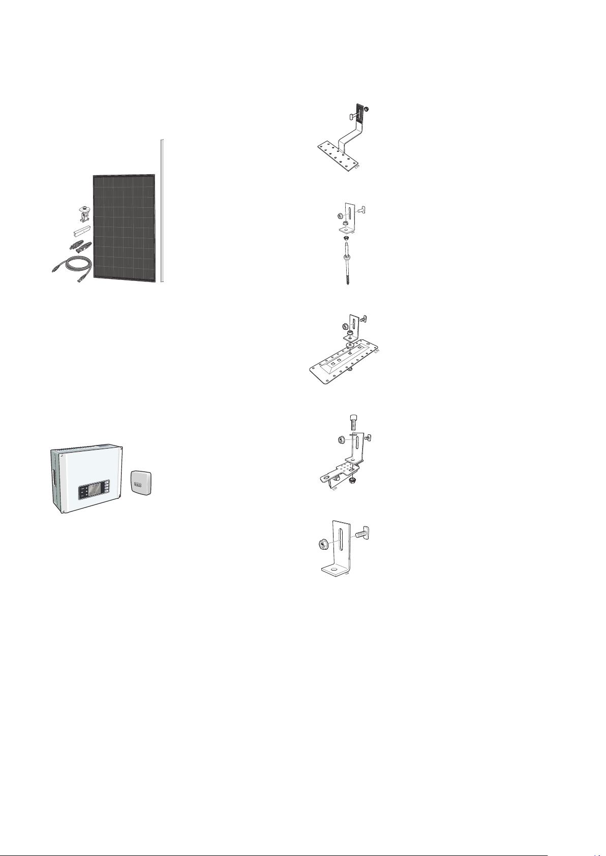
The enclosed materials are those required for the install-
ations described (see page 17). In special cases, they
may need to be supplemented. If unsure, contact the
supplier. Information regarding applicable standards and
regulations must be obtained prior to the installation and
commissioning of the solar panel system. The electrical
installation, and notification to the power supplier, must
be carried out by qualified electricians. The form for the
inverter must be enclosed with the notification (pre-
completed form is available on www.nibe.se) Please
note that the installation must not be put into use until
the power supplier has given its approval.
NOTE
Installation of a solar panel is an extensive in-
tervention on an existing roof. The roof cover-
ing, particularly on converted and inhabited loft
spaces or where the roof's minimum angle is
undersized (relative to the covering), may re-
quire further measures against moisture be-
cause of wind pressure and drifting snow, this
must be evaluated by the installer on a case to
case basis. The roof design must be able to
handle the wind and snow loading that can
occur in the region.
STATIC LOAD
The installation may only be carried out on roof surfaces
or support constructions with sufficient carrying capacity
and strength. The static load capacity of the roof and
roof construction must if necessary be examined before
the solar panels are installed. Great importance should
be placed on the condition of wood roof structures and
the potential of screwing the mounting devices for the
solar panels to the structure. The roof construction must
be reinforced if necessary. Inspection of the whole solar
panel installation in accordance with DIN 1055 part 4
and 5, or in accordance with country specific regulations
is required, in particular, in areas with snow fall and
strong winds. The characteristics of the installation's
location (prevailing wind direction, whirl winds etc.) must
also be included in the calculation/evaluation of whether
these could mean increased loads. The solar panels
must be installed so that snow drifts from snow guards
or caused by special conditions in the installation location
cannot occur in the vicinity of the solar panels.
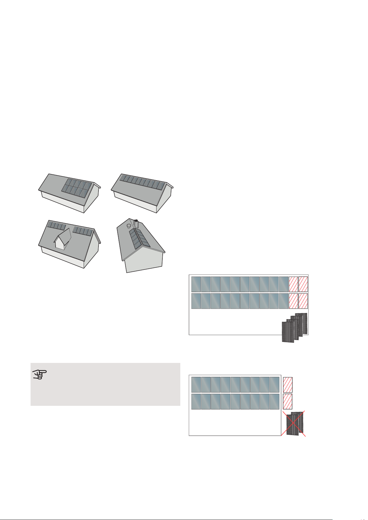
The distance from the outer edge of the roof must be
at least 1 m at the sides of roofs and 0.2 m at ridges
and roof trusses, this is to reduce the risk of the wind
ripping the solar panels off.
The installation system according to DIN 1055 part 5 for
snow zone II is intended for use up to 400 m above sea
level. If the installation is made on a tiled roof, it is re-
commended that the snow is cleared if it reaches a
depth of more than 30 cm on the solar panels (NOTE!
If the snow has melted, been packed down and then
more snow has fallen and so the density has increased,
the snow may need to be cleared - even though it is not
30 cm deep.)
If there is a risk that the snow will slide down onto the
panels and in particular behind the rear of raised panels,
snow guards must be installed to prevent this.
Ensure that the material under roofs with roof tiles is
sufficiently stable to support the roof mounting points.
Otherwise the roof must be reinforced. The installer
must evaluate this and make a decision, if uncertain a
structural engineer should be consulted. We recommend
that the roof tiles are cut down so that there are no point
loads between the roof and the roof brackets. The min-
imum distance between roof tiles at overlap points and
the underside of the brackets is 3 mm, this is in order
to allow for any movements in the mounting system in
reaction to the loads that occur.
LIGHTNING PROTECTION
If external lightning protection is installed, the solar
panels and the roof structure must be integrated so that
the solar panel field is protected from a direct lightning
strike. The combined solar panel area must be located
within the protective area provided by the lightning
protection. A safety distance of 0.5 m in all directions
from the solar panels to the periphery of the protected
area must be observed.
SAFETY INSTRUCTIONS
• Applicable safety regulations for working on roofs and
similar constructions must be followed.
NIBE PV Solar cell pack-
ageChapter 3 | Installation8
3 Installation

• Barriers to protect against falling parts must be in-
stalled. This is particularly important for high buildings
and locations where a lot of people pass below the
roof/under the building.
• Personal safety equipment or scaffolding must be
used when working on roofs, according to the applic-
able.regulations.
• Adequate measures must be taken during the install-
ation so that the solar panel does not come loose and
fall.
•Observe the safety distance to the current conducting
cables.
Installation and
positioning
The diagram shows insolation as a percentage of global
radiation in relation to surfaces at various orientations
and angles.
The map shows lines with the same global radiant flux,
i.e. the insolation measured at horizontal surfaces.
Source: SMHI.
100
112
107
90
107
850
900
1000
1000
1000
1050
1050
900
900 950
950
950
800
800
850
90
1200
South
Source: SMHI
Using the diagram and the map, one can estimate the
annual value of the solar radiation falling on those sur-
faces where the solar panels are located.
100% is the insolation at a horizontal surface, which in
southern Sweden is between 900 and 1200
kWh/m²/year. The angle of inclined surfaces is 45°.
1. Calculate the annual solar radiation using the map.
The specific solar radiation for the installation is ob-
tained as a percentage, based on the location of the
solar panel according to the diagram.
2. Multiply the results by the installation’s peak output
(e.g. 3 kW, 6 kW, 9 kW, 12 kW, 15 kW, 18 kW,
21 kW, 24 kW).
3. Multiply the result 2 by a constant 0.9 to calculate
the energy production in kWh/year (with a reserva-
tion for shade, dirt and snow coverage).
Example: Stockholm, 6 kW, 45°, installation south.
1000 x (112/100) x 6 x 0.9 = 6048 kWh/year
9Chapter 3 | Installation
NIBE PV Solar cell pack-
age

Installing solar panels
in several groups
Examples of possible combinations per ten panels:
To reduce the risk of damage to the electric cables
between the groups of solar panels, these can be run
underneath the roof tiles or ceiling. To prevent moisture
penetrating under the roof tiles or through the damp
barrier at the holes for the electrical cables, diffusion
sealed lead-ins must be fitted.
Specially adapted roof brackets for tiled roofs, sheet
metal roofs, felt roofs or seamed sheet metal roofs. The
type of roof bracket to be used must be specified at the
time of ordering.
Caution
Additional connectors and mounting materials
may be required to install solar panels in differ-
ent groupings.
MOUNTING
Each package can be expanded with additional panels,
or you can choose not to install some panels.
This means that you have extremely good flexibility, al-
lowing attractive roof installation.
If you need a larger installation, it is perfectly possible
to expand it. In this case, you simply select multiples of
e.g. 24 kW, producing an installation of e.g. 240 kW.
This can be done easily thanks to the modular system,
and you will then need 10 x 8 basic kits, 10 x inverters
and 10 x 8 sets of roof brackets.
Material
If the panels are installed in formations other than that
shown in the example, additional mounting materials
may be required. To order additional components or in-
stallation materials, contact:
NIBE AB Sweden
Box 14, Hannabadsvägen 5
SE-285 21 Markaryd
Tel: (+46)(0)433 73 000
Example
6 kW package installed on roof that is expanded by e.g.
four solar panels (7.2 kW)
LEK
LEK
LEK
LEK
6 kW package installed on roof where you have decided
not to install e.g. two panels (5.4 kW).
LEK
LEK
NIBE PV Solar cell pack-
ageChapter 4 | Mounting10
4 Mounting

Number of solar panels per string and per
package
The table shows how many panels you can have per
string, as well as how many panels are standard and
how many the inverter can cope with. The inverter has
dual trackers, allowing the installation of different num-
bers of panels per string. If the number of panels is not
sufficient to achieve the minimum number for two
strings, you have to install all the panels in one string.
String = a number of panels connected in series.
Max.
total
Min.
total
Std./
no.
Max./
string
Min./
string
Inverter for:
146101041.8 – 4.2 kW
2515201884.5 – 7.5 kW
35263021127.8 – 10.5 kW
423640211410.8 – 12.6 kW
634350**2x211412.9 – 18.9 kW
806080*2x21*2x1518 – 24 kW
*"2 equally long strings per input/tracker".
**"Tracker one can manage one string or two equally long strings"
Extra ceiling brackets are added when expanding.
Overview, assembly parts
NOTE
Ensure that the strength and load capacity of
the roof structure are sufficient.
NOTE
If there is not a sufficiently stable substructure
such as tongued and grooved boards or roof
trusses to allow a durable installation the roof
must be reinforced.
Roof bracket, stainless
steel Mounting rail, horizontal
Joint with rivet
Solar panel
Assembly clamp
Before installing solar panels
1.
2.
3.
4.
5.
5.
6.
19 mm
Roof bracket location
1
4
5
5
2
36
24 mm
1. Number of rows of installed solar panels x height of
solar panels (plus distance between the solar panels
where relevant).
2. Number of solar panels installed horizontally x (solar
panel's width + 24 mm) + 31 mm.
3. The horizontal distance between the mounting
points for the roof brackets must not exceed c-c
1200 mm.
4. Solar panel height
5. Vertical location of the mounting points = panel
height x 0.25.
6. Max distance between the last roof bracket and the
end of the mounting rail = 200 mm
Remove the roof tiles
Mark out the positions for the roof brackets using chalk.
Remove or slide up the marked roof tiles.
Caution
Illustration only, dimensions between roof
brackets according to section “Before installing
solar panels” on page 11.
11Chapter 4 | Mounting
NIBE PV Solar cell pack-
age

Installation of roof bracket in truss or in tongue
and groove
Upper row
Lower row
Roof bracket
Tongued
and
grooved
board/
Truss
XX
Secure each roof bracket in the roof trusses with 3 x
wood screws. 2 x screws are located in the lower row
and 1 x screws are located in the upper row (screws
not supplied).
Caution
The distance to the edge (X) must be the same
on both sides.
Installing the roof brackets in tongued and grooved
boards
Secure each roof bracket with 6 x stainless steel con-
struction screws, divided between the two rows (screws
not supplied).
Installing the spacer plate
Spacer
plate
Batten
Wood
screw
Tongued
and
grooved
board/
Truss
Roof tile Roof bracket
The roof bracket must not be pressed directly against
the roof tile. Use a spacer plate if necessary?
The spacer plate must be made of a water and weather-
resistant material (not supplied).
Adapting roof tiles
Use an angle grinder or hammer to make a cut out in
the part of the roof tile that covers the roof bracket, so
that the roof tile can lie flat against the roof base.
It may also be necessary to make a cut out in the roof
tile underneath.
Installing screw pins for mounting solar panels
on sheet metal roofs
3
2
1
UN
Roof profile
Battens
Counter-
battens
Tongued
and
grooved
board
Truss
4
1. Drill holes in the roof tile or use existing holes
2. Install the screw pin in the truss sufficiently deeply,
(all the threaded section must be screwed in), to
install a seal against the roof sheet. A bitumen based
roof and building sealant can be used - required for
textured (sanded) surfaces
3. Install the L profile, adjust the height to the other
screw pins
4. Ensure that the screw pin’s entire thread is screwed
into the roof truss.
NIBE PV Solar cell pack-
ageChapter 4 | Mounting12

Installing the mounting bracket for installing
solar panels on seamed metal roofs
LEK
Bolt M10
Washer
Mounting
L profile
Nut M10
1. Install the mounting on the roof according to the
usual rules and practice
2. Install the L profile with M10 bolt, washer and nut.
Installing the mounting bracket for installing
solar panels on felt roofs
x 10
LEK
LEK
Screw
Coach bolt M10
1. Install the plate on the roof according to the usual
rules and practice.
x 10
LEK
LEK
Coach bolt M10
Flashing tape
Rubber washer
L profile
Nut M10
2. Install the L profile on the protruding coach bolt with
M10 nuts.
Caution
The coach bolt should be installed from under-
neath before the plate is mounted on the roof.
Caution
Never use the installed roof brackets as a lad-
der.
Installing the mounting rails
Mounting rails are secured in the roof brackets with T
bolts and locking nuts (8 mm).
Caution
Check that the head of the T-bolt is vertical in
the mounting rail after tightening.
The rectangular hole in the roof bracket permits optimal
height adjustment of the mounting rail.
Adjustment of the mounting rail height
Adjust the first mounting rails installed in relation to each
other and the roof cladding. Then fix the mounting rail
to the roof bracket by tightening the nut. Tightening
torque 12-15 Nm.
13Chapter 4 | Mounting
NIBE PV Solar cell pack-
age

Join the mounting rails
Mounting rail
2 mm
Joint
Rivet
Slide the joint section with rivets into the mounting rail
until it catches firmly on the rivet (A). Slide the next
mounting rail in until it also catches on the rivet (B).
Leave a space of 2 mm to compensate for linear expan-
sion.
Installing solar panels in the first (bottom) row
Mounting rail
Assembly clamp
90°
Caution
The assembly clamps can be twisted and are
adapted for use both at the outer edges and
between the solar panels.
1. Position the first solar panel on the mounting rail.
2. Click the assembly clamp into the first (bottom) row
5 mm from the end of the mounting rail.
3. Secure the solar panel with the assembly clamp
screw, tighten to 8 Nm.
4. Click the assembly clamp into the installation rail on
the right-hand side of the solar panel. Slide the as-
sembly clamp towards the solar panel and connect.
5. Position the second solar panel on the mounting rail
and move the solar panel towards the assembly
clamp. Connect the cable to the previous solar panel.
Secure the wiring between the solar panels.
6. Tighten the assembly clamp, tighten to 12-15 Nm.
7. Install further solar panels according to point 4 to 6.
8. After the last solar panel in the row 1 has been posi-
tioned on the mounting rail and connected, the as-
sembly clamp is clicked into the mounting rail from
the right. Minimum distance between the assembly
clamp and the end of the mounting rail is 5 mm.
9. Secure the solar panel with the assembly clamp
screw, tighten to 8 Nm.
Caution
Secure the wiring between the solar pan-
els.
Caution
Take the return cable when installing the
panels. See section Electrical connec-
tion/Cable routing
Caution
Measure the voltage at the connected
panels on the roof before removing any
scaffolding.
Install the following rows in the same way.
NIBE PV Solar cell pack-
ageChapter 4 | Mounting14

Outline diagram
LEK
4 532
HB IJF JF HB 2 11 H1 IB5L
167 8 9 10 11 2TR HK
AIA 566
LEK
LEK
LEK
Internet
Solar panels
Inverter
Electrical
distribution unit
Energy meter
Mains network
NIBE Uplink
SMO 20
Heat pump
EME 20
Own use
NOTE
Electrical installation and service must be car-
ried out under the supervision of a qualified
electrician, and in accordance with applicable
electrical safety regulations.
On the reverse of the solar panels there is a factory in-
stalled connection box prepared with wiring for positive
and negative connections. The cables are fitted with
quick-release connectors.
The electrical cables between the panels and the inverter
must be double insulated and UV/weather-resistant
Photovoltaic cables, 4 mm² up to 100 m length (not
supplied).
The inverter is connected and fused to group central as
though it were a load with the same output. The inverter
includes a factory-fitted 300 mA earth-fault breaker. If
the inverter is to be connected to an external earth-fault
breaker, this must be 300 mA or larger.
15Chapter 5 | Electrical connection
NIBE PV Solar cell pack-
age
5 Electrical connection

INSTALLING
CONNECTORS ON DC
WIRING
DC connectors of the MC-4
type are supplied with all
packages.
1. The connector’s sleeve
must not be disconnected until
the cable has been inserted
into the connector.
1
15 - 16,5 mm
2. Strip the cable 15-16.5 mm
2
3. Twin the cable’s strands.
4
CLICK
4. Insert the cable into the
connector until a “click” is
heard.
5
Test
5. Check that the cable is se-
curely in place by carefully
pulling it.
6
3 - 4 Nm
6. Fasten the connector’s
sleeve so that the cable is se-
cure and so that the sleeve is
at the bottom (3-4 Nm)
Caution
Check that the polarity is correct when connect-
ing to the inverter.
CONNECTING INVERTERS
For assembly and installation, consult the quick guide.
For more information about the inverter, consult the
enclosed manual.
QUICK GUIDE
Installation area
300mm 200mm
200mm200mm 500mm
500mm 500mm
500mm
300mm 200mm
200mm200mm 500mm
500mm 500mm
500mm
NIBE PV Solar cell pack-
ageChapter 5 | Electrical connection16

Hole pattern for the bracket
a
b
c
d
f
e
PVI 10-24PVI 10-6, 10-9,
10-12, 10-15
PVI 10-3
457 mm250 mma
228.5 mm125 mmb
117.5 mm177 mm120 mmc
222 mm340.5 mm240 mmd
200 mm-e
400 mm265 mmf
Fitting the wall bracket
Fitting the inverter
Single-
phase
Three-
phase
Fit the inverter on the wall bracket according to the dia-
gram above.
The inverter must also be earthed as illustrated, then
cover the switch with silicone to protect against corro-
sion.
Switch
10~12mm
40~45mm
L1
L2
L3
N
PE
10 mm
Pin 1 L1
Pin 2 N
Pin 3 PE
Inverter side
Tighten anticlockwise.
Tighten these screws and
check that the screw heads
do not protrude
4 mm² copper wire
Copper wire
Crimp onto the
cable
Three-
phase
Single-
phase
17Chapter 5 | Electrical connection
NIBE PV Solar cell pack-
age

RS485 - Communication
PVI 10-20
Others
FunctionConnection
RS485 +1
RS485 -2
Not used3
Not used4
RS485 +5
RS485 -6
Inspection of the installation
Check that all screws and cable grommets are tightened
and sealed.
The guarantee does not cover faults caused by
screws/cable grommets that have not been tightened.
Set time and date.
Set Language
2 s
2000-00-00 00:00
2 s
1234567890
Normal
20 s
Normal
2018-09-07
Error log
Date &Time
Language
Histogram
SetTime
11:20:25
2018-09-07
2018-09-07
2 s
Three-
phase
Single-
phase
NOTE
For connection in an IT network with 230 V
between the phases, only inverter PVI 5-3 can
be used. Specify when ordering. Applies to
Norway.
NIBE PV Solar cell pack-
ageChapter 5 | Electrical connection18

CONNECTING EME 20
See separate IHB for EME 20
CABLE ROUTING
Cable with pre-installed connectors (2 x 7 m) is supplied
and can be used for roof installation.
NOTE
In order to minimise the risk of induced
voltages in the event of lightning, the return
cable must be laid together with connection
cables for the panels connected in series.
Grounding solar panels
Solar panels must be earthed in the inverter or an extern-
al junction box.
Solar cell modules
Ground
cable
Ground
cable
Safety breaker
Inverter
Electrical
distribution
unit
Electrical
distribution
unit
Lightning protection
For information regarding lightning protection, see page
8under "Installation".
FUNCTIONS
NIBE Uplink
With NIBE Uplink and the Internet, you can
obtain a quick overview and the current status
of the solar panel system on your property. You
obtain easy-to-grasp and good supporting data, where
you can see the current power and the history. In the
event of any malfunction, you also receive an alarm dir-
ectly to your e-mail, which allows you to take counterac-
tion quickly.
This is included if you already have a NIBE machine that
can handle NIBE Uplink. If you want to use NIBE Uplink
but do not already have a NIBE machine, SMO 20 can
be used.
For communication with SMO 20, cable part no. 718576
is required (ordered separately).
19Chapter 5 | Electrical connection
NIBE PV Solar cell pack-
age

Service
The solar panels must be regularly inspected.
Check that the glass, reverse and aluminium frame are
undamaged.
Check that all electrical wiring and connections are intact
and not coated with anything.
Mechanical cleaning is not usually required and is not
recommended.
NIBE PV Solar cell pack-
ageChapter 6 | Maintenance20
6 Maintenance
Table of contents
Other Nibe Inverter manuals
Popular Inverter manuals by other brands

Pulsar
Pulsar PG1202S Operator's manual

Nord Drivesystems
Nord Drivesystems BU 0830 Functional safety guide

AEC
AEC TOUGH Series installation manual

SMA Solar Technology
SMA Solar Technology Sunny Boy 2500 user manual

SamplexPower
SamplexPower PST-1500-12 owner's manual

Link electronics
Link electronics 1199 Specification sheet

GMDE
GMDE Powervortex4600TL user manual

Victron energy
Victron energy BlueSolar MPPT 150/45-Tr manual

Phocos
Phocos CXup 10 user manual

Magnum Energy
Magnum Energy MMS1012 owner's manual

Badger Power Electronics
Badger Power Electronics BPE600 Installation & user manual

Wagan
Wagan Slimline Plus 1250 user manual