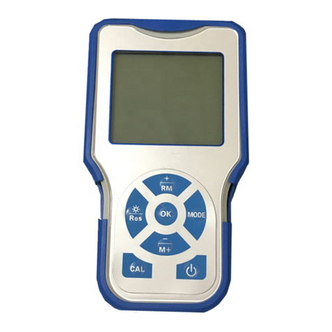
Nic WA-5F User manual

Mercury Analyzer
WA-5F
Instruction Manual
NIC-600-2246-07
Nippon Instruments Corporation

NIC-600-2246-07
Mercury Analyzer WA-5F
Instruction Manual
Table of Contents
1. Introduction ..................................................................................................................... 1
Safety precautions................................................................................................... 1
1.1.1. Meaning of safety alert symbols....................................................................... 1
1.1.2. Installation precautions..................................................................................... 1
1.1.3. Maintenance precautions ................................................................................. 1
System Outline......................................................................................................... 2
2. Operating Principle......................................................................................................... 3
Atmospheric mercury measurement by double amalgam method.......................... 3
Part names and functions........................................................................................ 4
2.2.1. Front.................................................................................................................. 4
2.2.2. Rear.................................................................................................................. 5
2.2.3. Internal components viewed from the right...................................................... 6
2.2.4. Internal components viewed from the left ........................................................ 7
3. Specifications.................................................................................................................. 8
Standard configuration............................................................................................. 8
Component specifications........................................................................................ 8
4. System installation ......................................................................................................... 9
Conditions for installation......................................................................................... 9
4.1.1. Environment for installation.............................................................................. 9
4.1.2. Power supply.................................................................................................... 9
Installation and connections .................................................................................. 10
4.2.1. WA-5F............................................................................................................. 10
Software setup....................................................................................................... 11
4.3.1. Installation of WA5Win ................................................................................... 11
4.3.2. Network setting............................................................................................... 12
4.3.3. Configuration setup ........................................................................................ 14
How to uninstall...................................................................................................... 15
5. Measurement................................................................................................................. 16
Measurement Operation Flowchart....................................................................... 16

NIC-600-2246-07
Items essentially required for measurement.......................................................... 17
System startup....................................................................................................... 18
5.3.1. WA-5F startup................................................................................................. 18
5.3.2. Startup of control software.............................................................................. 18
5.3.3. System check ................................................................................................. 19
Condition setting.................................................................................................... 21
5.4.1. Setup of measurement method...................................................................... 21
5.4.2. Blank check condition..................................................................................... 22
5.4.3. Setup of table conditions................................................................................ 23
Creation of calibration curve.................................................................................. 24
Measurement of unknown sample (Collector)....................................................... 29
Measurement of unknown sample (Liquid) ........................................................... 31
Measurement of unknown sample (Direct Sampling) ........................................... 33
Printing a report ..................................................................................................... 34
Suspension of measurement................................................................................. 34
Finish measurement .............................................................................................. 34
6. WA5FWin........................................................................................................................ 35
screen .................................................................................................................... 35
6.1.1. SEQUENCE screen........................................................................................ 35
6.1.2. PROFILE screen............................................................................................. 35
6.1.3. CALIBRATION screen.................................................................................... 36
6.1.4. TABLE screen................................................................................................. 36
6.1.5. Common parts................................................................................................ 36
6.1.6. Status bar ....................................................................................................... 37
6.1.7. Table window.................................................................................................. 37
Common items..............................................................................................37
STD...............................................................................................................38
SMP ..............................................................................................................40
List of menu commands......................................................................................... 43
6.2.1. File menu........................................................................................................ 43
New...............................................................................................................43
Open .............................................................................................................44
Save as.........................................................................................................44
Page setup....................................................................................................45
Print Preview.................................................................................................46
Print...............................................................................................................47
6.2.2. Edit menu........................................................................................................ 48
Copy..............................................................................................................48
Cut.................................................................................................................48
Paste.............................................................................................................48

NIC-600-2246-07
Remove.........................................................................................................48
Insert .............................................................................................................48
Move .............................................................................................................49
Save as csv file.............................................................................................49
Save as jpg File ............................................................................................49
Add data........................................................................................................49
6.2.3. Run menu....................................................................................................... 50
Start...............................................................................................................50
Stop...............................................................................................................51
Emergency....................................................................................................51
Reset.............................................................................................................51
Equipment-Check .........................................................................................51
Measurement Condition ...............................................................................52
Standard gas preparation.............................................................................55
Flow adjust/Leak check ................................................................................56
START & Heater OFF...................................................................................57
Heater OFF...................................................................................................58
Maintenance .................................................................................................59
6.2.4. Table menu..................................................................................................... 65
Memo Setup .................................................................................................65
Table Conditions ...........................................................................................66
Statistical calculation result...........................................................................68
Sample name registration.............................................................................68
Equipment check result display....................................................................69
6.2.5. System menu.................................................................................................. 70
Setup of IP Address (WA5/WA5Win)............................................................70
Setup.............................................................................................................72
Color Set.......................................................................................................74
Firmware update...........................................................................................75
If the firmware failed to be updated ..............................................................76
6.2.6. Window menu................................................................................................. 77
Screen Change (Sequence Screen) ............................................................77
Screen Change (Profile Screen)...................................................................77
Screen Arrangement Initialization.................................................................77
Sequence Log and Error History Labeling ...................................................77
6.2.7. Help................................................................................................................. 78
About.............................................................................................................78
How to determine a calibration curve.................................................................... 79
6.3.1. 1 Linear formula.............................................................................................. 79
6.3.2. 3 Cubic formula............................................................................................... 79
Calculation formula for mercury amount and concentration.................................. 81

NIC-600-2246-07
Mercury content of standard gas........................................................................... 82
7. Maintenance................................................................................................................... 83
Check items ........................................................................................................... 83
7.1.1. Daily check ..................................................................................................... 83
7.1.2. Annual check.................................................................................................. 84
Error and warning .................................................................................................. 85
Troubleshooting..................................................................................................... 88
7.3.1. Reduction in sensitivity................................................................................... 88
7.3.2. Abnormal blank (Increase) ............................................................................. 89
7.3.3. Abnormal sensitivity (Increase)...................................................................... 89
Maintenance........................................................................................................... 90
7.4.1. Leak check...................................................................................................... 90
7.4.2. Replacement of septum.................................................................................. 91
7.4.3. Dismounting of gas washing bottle/dehumidifying bottle............................... 91
7.4.4. Detachment/Attachment of the cover............................................................. 92
7.4.5. Mounting/Dismounting of collector tube (H2)................................................. 92
7.4.6. Dismounting of absorption cell....................................................................... 93
7.4.7. Cleaning the absorption joints........................................................................ 94
7.4.8. Procedure for decreasing blank level of collector tube.................................. 95
8. Contact........................................................................................................................... 96

NIC-600-2246-07 1. Introduction
1
1. Introduction
Safety precautions
1.1.1. Meaning of safety alert symbols
Warning
Indicates that incorrect handling could result in the death or severe injury
to the operator.
Caution
Indicates that incorrect handling could result in moderate or minor injuryto
the operator, or damage to property.
1.1.2. Installation precautions
Warning
· Be sure to connect the protective grounding to prevent electric shock.
1.1.3. Maintenance precautions
Caution
· Shut OFF the power supply before staring the maintenance work. Otherwise
electric shock may occur.
Caution
· Maintenance of the heater must be carried out after the power has been turned
OFF and the heater has cooled down close to normal room temperature or it could
result in burns.
· Be careful when touching or handling any of the glass components or they could
be broken.
·

1. Introduction NIC-600-2246-07
2
System Outline
WA-5F is a mercury measuring system that features quick, simple operation, high
sensitivity and high accuracy measurement of the amount of mercury collected in a
mercury collector tube dedicated for the system.
The system can be operated and used for processing measurement results through a
PC, allowing for various analysis including statistic calculation.
Furthermore, it is possible to measure automatically more than one collector tubes
continuously by connecting an optional sample changer.
Automatic measurement of a sample in a Tedlar® bag is also possible by connecting a
dry gas meter dedicated for the system.
Please be sure to read this manual before using the system to ensure correct
measurement of mercury.
* The system and the dry gas meter option kit
WA-5F

NIC-600-2246-07 2. Operating Principle
3
2. Operating Principle
Atmospheric mercury measurement by double amalgam method
The system heats mercury collector tubes, which ambient air/fuel gas has passed through,
in the heating furnace (H1) by passing air containing no mercury. The mercury trapped in
gold amalgam is released as gaseous mercury during being heated. Any acidic contents that
disturb the detection of mercury are removed in a gas washing unit, and then the gas is
cooled down to remove moisture from it. By passing the gas through the re-collecting furnace
(H2) heated at approximately 165°C, only mercury is re-collected as gold amalgam and the
interference from coexisting components is prevented.
The detection principle is Atomic Fluorescence Spectroscopy at 253.7nm. Mercury is
released from the mercury collector by heating under Argon gas flow and it emits the
fluorescence light in the AFS cell.
* Flow diagram of dry gas meter connection.
Flow Diagram

2. Operating Principle
NIC-600-2246-07
4
Part names and functions
2.2.1. Front
No.
Name
Remarks
STD injection port
A built-in septum provided
Collector tube heating furnace (H1)
A built-in cooling fan provided
Collector tube mount port
Made of fluoroplastic
Electronic cooler unit
Gas washing bottle
Removes any acidic gas by washing.
The standard buffer solution (1+1) is used for
measuring ambient air.
NaOH 0.1M is used for reducing vaporization.
Dehumidifying bottle
Removes moisture
To detector
Valve for connecting options
Flow control needle
Adjusted to 0.5L/min

NIC-600-2246-07 2. Operating Principle
5
2.2.2. Rear
No.
Name
Remarks
①
Argon gas inlet
Connected to the argon gas tube (O.D 6mm)
②
OUTLET
Connected to the exhaust tube (O.D. 6mm)
③
Power
④
Fuse
100V10A or 250V5A
⑤
Power cable connection port
AC100~240V
⑥
AC OUT
Power supply port for the sample changer
* Interlocked with the main switch
⑦
PC connection port
Connected through a LAN cable
⑧
Serial connection port
(not used)
⑨
Dry gas meter connection port
⑩
Option
(not used)
⑪
Sample changer (signal)
Connected to the cable for control
⑫
Sample changer (Power)
Connected to the cable for drive
⑪
⑫

2. Operating Principle
NIC-600-2246-07
6
2.2.3. Internal components viewed from the right
No.
Name
Remarks
○
1
Valve V1
Switches carrier gases for sampling/detection
○
2
Re-collecting furnace (H2)
A built-in cooling fan provided
○
3
Valve V3
Switches the detector bypass
○
4
Valve VF
For backflow prevention
○
5
Air pump
○
6
Flow control needle
Adjusted to 0.5L/min
○
7
Flow sensor
For measurement of flow rate
○
8
Activated carbon filter for
carry air
For cleaning of carrier gas during trans-sampling
○
9
Collector-tube for carry
argon
For cleaning of carrier gas during measurement
○
10
Activated carbon filter for
exhaust air
For removal of mercury from measurement
exhaust gas
○
11
Mass flow controller
For argon gas flow control
①
②
③
④
⑤
⑥
⑦
⑧
⑨
⑩

3. Specifications NIC-600-2246-07
8
3. Specifications
Standard configuration
(1) Mercury analysis system WA-5F
(2) Data analysis/System control software WA5Win
(3) Standard accessories
(4) Personal computer
Component specifications
(1) Mercury analysis system WA-5F
Analysis method : Atomic Fluorescence System
Light source : Low pressure mercury discharge tube
Detector : Photoelectric tube
Carrier gas : Air, Argon
Pump : Diaphragm pump
Flow rate : 0.1 -1.0L/min (variable)
Flow control : Precision needle valve
Flow sensor : Electronic flow sensor
Target of measurement : Mercury collector tube
Measurement principle : Non-dispersion triple-beam cold-vapor atomic
absorption
Detection limit : 0.1pg(LOW range), 10pg(HIGH range)
Measuring range : 0.0001 -1,000ng
LOW range : ~10ng
HIGH range : ~1000ng (Linier 100ng)
Data communication : Ethernet
Dimension/Weight : 230W x 460D x 390H, 13kg
(2) Data analysis/System control software WA5Win
OS : Windows 11 Pro, Windows 10 Pro
(Microsoft Edge or Internet Explorer 11 is necessary)
System control : Control of analysis conditions, Error indication
Data processing : Construction of calibration curve, Concentration
calculation, Statistical calculations

NIC-600-2246-07 4. System installation
9
4. System installation
Conditions for installation
4.1.1. Environment for installation
Operating ambient temperature : 10 - 40°C
Operating ambient humidity : 10 - 80%RH (no dew condensation)
Storage ambient temperature : 0 - 50°C
Storage ambient humidity : 10 - 80%RH (no dew condensation)
Vibration : No vibrations strong enough to be felt by the human
body.
Dust, Fume : Clean environment free of fumes, dust, and others
which could affect the measurement. (No
smoking)
Installation space : 500W x 500D (mm) or larger with a rigid foundation
and capable of supporting a weight of about 30kg.
Argon gas : 99.99 vol% or more, 0.15~0.25MPa
Argon gas consumption : 0.5L at LOW range, 0.8L at HIGH range per one
analysis
Others : Install the unit in a place not exposed to direct
sunlight or air flow from an air conditioners or
blower.
Special note : Never install the system in a room in which volatile
halogen-based reagents such as organic chlorine
solvents are handled. Also avoid installation in a
room which those gases can enter.
4.1.2. Power supply
Power voltage : Single phase 100 to 240V, 50/60Hz
Voltage fluctuation : Within ±5%
Capacity : 500VA (3 pole plug)
Fuse : 10A
Power quality : No surges, harmonics, or noise.
Distance from power outlet to the system : Within 2m. Grounding required.

4. System installation NIC-600-2246-07
10
Installation and connections
4.2.1. WA-5F
(1) Place WA-5F and a PC in an installation location.
(2) Connect WA-5F and the PC with a supplied LAN cable.
(3) Plug in the power cable and connect it to the power source.
(4) Adjust 0.15~0.25Mpa of Argon pressure and connect with 6mm of plastic tube.
(5) Connect the signal cable of the gas meter (when the optional gas meter is
connected).
(6) Connect the OUTLET and the dry gas meter with a tube.
(7) Connect a tube to the dry gas meter OUT and connect the other end to exhaust
equipment such as draft system.
* Be sure to connect the exhaust tube when measuring gases such as LPG. Mercury in
a gas to be measured is removed with activated carbon dedicated for mercury removal
but the removal of any other gasses contained in a sample cannot be guaranteed.
* When mounting the thermocouple on the dry gas meter, remove the thermocouple
once together with the packing rubber and then screw in the joint and then insert
the thermocouple.
LAN cable
Power cable
Power switch
Tube
connection
Dry gas meter
cable
connection
Exhaust gas
connection
Argon line

NIC-600-2246-07 4. System installation
11
Software setup
Set up the software to use WA-5F by following the steps below.
①Installation of WA5Win
②Network setting
4.3.1. Installation of WA5Win
* IF the OS language setting is not English (United States), please set as follows.
Control Panel – Clock, Language, and Region – Change date, time, or number formats
Format: English (United States)
* Close all application programs if they run on Windows.
* Log on to Windows with the account of a user who has administrator right to install the
application program.
(1) Insert the attached CD-ROM into the drive and, when
"Welcome to the WA5Win Setup Wizard" window is
displayed on the screen, click Next.
(2) The “Select Installation Folder” window is displayed.
Normally click Next if you wish to install the software in
the default folder. If you wish to change the installation
folder, click Browse... and select the folder.
(3) When the “Confirm Installation” window is displayed,
click Next. Installation will start.
(4) Once installation is complete, the "Installation Complete"
window opens. Click Close to close the window.
The installation is completed

4. System installation NIC-600-2246-07
12
4.3.2. Network setting
An IP address and subnet mask of the network adapter used by WA5Win should be set for
the communication between WA-5F and WA5Win.
WA-5F occupies the IP address of 192.168.2.2” and WA5Win occupies the IP address of
“192.168.21” at the default setting. Therefore the IP address of the network adapter should
be set to “192.168.2.1” and the subnet mask should be set to “255.255.255.252”
accordingly.
* If a PC on which WA5Win is installed is connected to the network, WA5Win may not run
due to the duplication of IP addresses. Do not connect the PC to the network until the
setting is completed.
(1) Click “Control Panel” on “Start Menu”
to display the Control Panel. Then
click “View network status and tasks”
in [Network and Internet].
(* Click “[Network and Sharing
Center] icon if “View by Icon” is
selected.)
(2) Click [Change adapter settings] in the
menu on the left.
(3) Right-click [Local Area Connection]
icon and then click [Properties].

NIC-600-2246-07 4. System installation
13
(4) Select [Internet Protocol Version
4(TCP/IPv4)] and click [Properties].
(5) Set the IP address and the subnet
mask.
IP address: 192.168.2.1
Subnet mask: 255.255.255.252
Then Click [OK] to complete the setting.
* If the IP addresses are found to duplicate with the existing ones after the setting, it is
possible to select a pattern where 192.168.219.253 and 192.168.219.254 are used.
Refer to “6.2.5.1.Setup of IP Address (WA5/WA5Win) ” for how to change.

NIC-600-2246-07 4. System installation
15
How to uninstall
Follow the procedure below to uninstall WA5Win.
When WA5Wiin is reinstalled, first uninstall it.
(1) Click “Control Panel” on “Start Menu”
to display the Control Panel. Then
click “Uninstall a program”.
(* Click [Program and Function] icon if
“View by Icon” is selected.)
(2) Double-click “WA5Win”.
Then follow the instructions displayed on the screen to uninstall the program.
Other manuals for WA-5F
1
Table of contents
Other Nic Measuring Instrument manuals
Popular Measuring Instrument manuals by other brands
SICK
SICK FLOWSIC30 Installation, operation and maintenance guide
Dynex
Dynex DYNAREAD 5206 Service manual
Agilent Technologies
Agilent Technologies 4339B Operation manual
AETOOL
AETOOL BESA 12 user manual
SPL-Laboratory
SPL-Laboratory Smart Voltmeter 2014 user manual
YASKAWA
YASKAWA 1000 Series installation manual


