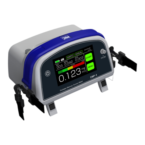
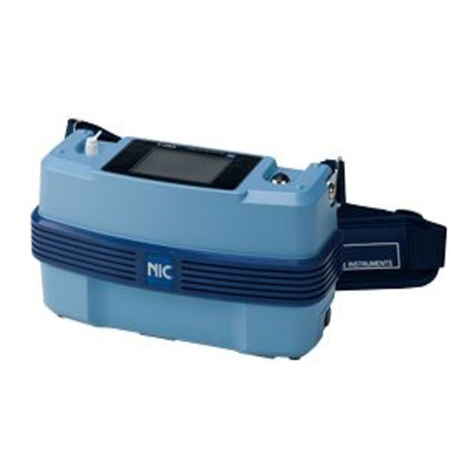
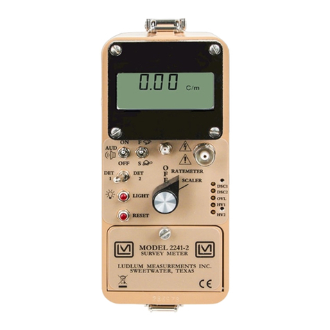
Nic Mercury/EMP-2 User manual

Mercury Survey Meter for Work
Environments
Mercury/EMP-2(for WLE)
Instruction Manual
NIC-TD-0000025-00
Nippon Instruments Corporation

NIC-TD-0000025-00
Mercury Survey Meter for Work Environments
Mercury/EMP-2(for WLE) Instruction manual
- Contents -
1. Introduction ................................................................................................ 1
1.1. Safety precautions.................................................................................................. 1
1.1.1. Safety symbols .......................................................................................................1
1.1.2. Common precautions to take with the main body of the equipment, the batteries,
and battery charger................................................................................................................1
1.1.3. Precautions regarding the main body of the equipment.........................................2
1.1.4. Precautions regarding the batteries .......................................................................3
1.1.5. Precautions regarding the battery charger.............................................................4
1.2. Equipment overview................................................................................................ 5
2. Principles....................................................................................................6
2.1. Operation ................................................................................................................ 6
2.2. Description of individual parts................................................................................. 7
2.2.1. Top of main unit......................................................................................................7
2.2.2. Bottom of main unit................................................................................................. 8
3. Specifications............................................................................................. 9
3.1. Standard configuration............................................................................................ 9
3.2. Specifications of each apparatus............................................................................ 9
4. Measurement ........................................................................................... 11
4.1. Flow chart of measurement.................................................................................. 11
4.2. Preparation before power-up................................................................................ 13
4.2.1. Checking the battery charge status......................................................................13
4.2.2. Checking the SD card...........................................................................................13
4.2.3. Checking the probe connection............................................................................14
4.2.4. Confirming the equipment usage conditions ........................................................14
4.3. Measuring operation............................................................................................. 16
4.3.1. Power-up ..............................................................................................................16
4.3.2. STAND-BY screen................................................................................................17
4.3.3. READY screen......................................................................................................18
4.3.4. Pre-measurement confirmation............................................................................23
4.3.5. Measurement screen............................................................................................25
4.3.6. Ending a measurement ........................................................................................29
5. MENU screen........................................................................................... 30
5.1. Simplified Calibration............................................................................................ 30
5.1.1. Calibration method ...............................................................................................31
5.1.2. Method of preparing a standard mercury gas ......................................................34
5.2. Setting the measurement conditions (Setting) ..................................................... 36
5.2.1. Full-scale value of the level meter........................................................................37
5.2.2. Alarm-generating level..........................................................................................37
5.2.3. Amount of mercury adsorbed by the zero filter ....................................................38
5.2.4. Current time..........................................................................................................39
5.2.5. Unit of measured mercury concentration .............................................................39
5.2.6. Measurement mode..............................................................................................39

NIC-TD-0000025-00
5.2.7. Sig/Ref Voltage Regulation ..................................................................................40
5.2.8. Normalization Temperature..................................................................................42
5.2.9. WLE solution replacement cycle ..........................................................................42
5.2.10. WLE solution replacement time............................................................................42
5.2.11. Measurement cycle time in static mode ...............................................................43
5.3. Confirmation of measured data (Data Check)...................................................... 43
5.4. Maintenance ......................................................................................................... 45
5.5. EMP-2/WLE.......................................................................................................... 47
6. Measured data ......................................................................................... 48
6.1. Instantaneous value data...................................................................................... 48
6.2. Average value data............................................................................................... 49
7. Maintenance............................................................................................. 50
7.1. Inspection items.................................................................................................... 50
7.1.1. Daily inspections...................................................................................................50
7.1.2. Yearly inspections ................................................................................................50
7.2. Errors and warnings.............................................................................................. 51
7.2.1. Exchange Lamp....................................................................................................52
7.2.2. Exchange Pump ...................................................................................................52
7.2.3. Exchange ZERO Filter..........................................................................................53
7.2.4. Battery Empty.......................................................................................................54
7.3. Maintenance ......................................................................................................... 56
7.3.1. Replacing the zero filter........................................................................................56
8. Spares...................................................................................................... 57
9. Optional accessories................................................................................ 57
10. Contact..................................................................................................... 58

NIC-TD-0000025-00
1. Introduction
- 1 -
1. Introduction
1.1. Safety precautions
1.1.1. Safety symbols
Warning
Denotes that incorrect handling could pose a specific potential hazard that
may result in serious injury or death to the operator.
Caution
Denotes that any incorrect handling could pose a specific potential hazard
that may result in minor or moderate injury to the operator and/or damage
to property.
1.1.2. Common precautions to take with the main body of the equipment, the
batteries, and battery charger
· Do not use or leave the equipment anywhere it will be exposed to high
temperatures (e.g. in the vicinity of a fire or heater or in intense sunlight). Failure
to observe this could result in the equipment igniting or exploding, or fire.
· Do not allow your hands, fingers or other body parts to come into contact with the
charging terminals or other connecting terminals while power is being supplied to
the equipment. Failure to observe this could result in an electric shock, injury, or
failure of the equipment.
· Do not use the equipment if thunder can be heard outdoors, or lightning could
strike or electric shock occur.
· Customers are advised not to disassemble, modify, or repair the equipment as
doing so can be very dangerous. Failure to observe this could result in the
equipment failing or igniting, or electric shock or injury. Please note that we can
accept no responsibility for any failures or problems that have occurred with the
equipment, batteries, battery charger, or other components due to modifications
made by a customer.
· Ensure not to splash any water or other liquids onto the equipment. Never use the
equipment anywhere it could be directly exposed to water etc. or in humid
locations such as bathrooms; and never use the equipment with wet hands.
Failure to observe this could result in electric shock, shorting of the electronic
circuits, or a failure due to corrosion. (Use special caution in the rain or snowfall,
and at the seaside or anywhere near water, etc.) If the equipment is exposed to any
liquids, ensure to immediately turn off the power switch.
Warning

1. Introduction
NIC-TD-0000025-00
- 2 –
· Do not store or place the equipment anywhere it will be exposed to direct sunlight
(e.g. in automobiles), high or extremely low temperatures, or in moist or dusty
locations. Failure to observe this could result in deterioration, for example
discoloration or deformation, and/or result in a failure.
· Do not place the equipment on a wobbly base or in inclined or other unstable
locations, or the equipment could fall, thus causing injury or breaking it. In
addition, ensure it is not exposed to any shocks or other external forces.
· Ensure to observe the rating of electric outlets and wiring accessories during use.
If any of those ratings is exceeded, for example by too many appliances being
plugged into one outlet, the resulting heat generated could result in fire.
· Do not forcibly remove the SD card from the slot. Failure to observe this could
result in a failure or loss of the internal data.
· The equipment being damaged due to a fall could result in internal parts of the
equipment being exposed. In this case, ensure not to touch any of the exposed
parts, or you could suffer an electric shock or be injured by the damaged part.
Contact our agency or service representative as soon as possible.
1.1.3. Precautions regarding the main body of the equipment
· Ensure to completely remove the power supply before carrying out any
maintenance, or it could result in an electric shock.
· Do not insert any foreign matter such as liquids, metal or flammable objects into
the SD card slot. Failure to observe this could result in fire, an electric shock, or
failure of the equipment.
· In very rare cases, some people can develop symptoms such as temporary muscle
spasms or loss of consciousness when exposed to the stimulus of intense light or
a repeatedly blinking screen. If you have had any such experience, ensure to
consult a doctor before using the equipment.
· The structure of the equipment is not waterproof. The equipment getting wet from
rain or for any other reason could result in a failure or electric shock. Ensure the
equipment is kept dry.
· This equipment should be used 2,000m altitude and under.
· Do not disassemble or modify the equipment. Contact our agency or service
representative when inspections, adjustments, or repair of the internal parts need
to be made.
· Avoid any strong shocks or impact to the LCD screen, or the glass could break,
thus resulting in an injury.
· Avoid any strong shocks or impact to the equipment, for example by allowing it to
fall or objects hitting it.
Caution
Warning
Caution

NIC-TD-0000025-00
1. Introduction
- 3 -
1.1.4. Precautions regarding the batteries
· The batteries being left or placed anywhere at a high temperature of over 60°C or
those being deformed by an external force could result in ignition or explosion,
and thus great danger. Ensure the batteries are used within an ambient
temperature range of 0 to 45°C.
· Any of the batteries breaking could result in electrolyte leaking out, which could
then adhere to the skin or clothing. In such a case, immediately wash any
electrolyte away with water as it could be harmful. Furthermore, if any electrolyte
gets into your eye(s), ensure to rinse them with water without rubbing them and
then immediately consult a doctor, or it could result in loss of your eyesight.
· Ensure to insert the batteries with the correct polarity into the main body of the
equipment and battery charger. The incorrect polarity could result in them
exploding, catching fire, or heat being generated. If the batteries do not fit in place,
ensure not to push them in too forcefully. Carefully check the connections again
before attempting to reinsert them.
· Ensure not to short out any of the terminals such as the plugs and jacks. Pay
special attention to metallic parts such as necklaces, and staples. Before storing
them, protect the parts by affixing insulation tape to them or by other means, or
fire or burning could result.
· Do not modify or disassemble any of the batteries. Failure to observe this could
result in fire, burns, or failure.
· Do not expose the batteries to any water, seawater, coffee, or other liquids. The
batteries being wet could result in heat being generated, an explosion or fire; so
ensure to immediately disconnect the plug. Do not to attempt to charge any wet
batteries.
· If a battery emits any smoke or an unusual odor or is overheating, ensure to
immediately turn off the power and disconnect all the plugs.
· Do not damage, work on, pull or twist the power cable. Ensure not to use any
damaged cords. Failure to observe this could result in an electric shock, short
circuit, or fire.
· Ensure to hold the plug when connecting and disconnecting it. Holding the cord
only can result in excessive force to the lead wire and a break in the wire or failure
of the equipment.
· In extremely high- and low-temperature environments, the capacity of the batteries
will be decreased and thus shortening the available operating time (of the
equipment per battery charge). The battery life will also be decreased. Do not keep
or store the batteries at any temperature below 0°C or above 45°C.
· Before discarding any dead batteries, ensure to seal the terminal area with
insulation tape and then dispose of it appropriately in accordance with
government ordinances and regulations.
Warning
Caution

1. Introduction
NIC-TD-0000025-00
- 4 –
1.1.5. Precautions regarding the battery charger
· Do not charge any batteries using anything else but the dedicated AC adapter.
Failure to observe this could result in fire or electric shock.
· Do not use the AC adapter to charge any batteries other than those used in the
equipment. Ensure not to short any of the terminals such as the plugs and jacks.
Failure to observe this could result in fire or electric shock.
· Ensure to disconnect the power plug before maintaining or cleaning the battery
charger. Wipe away any dust around the power plug and jack, or it could result in
fire.
· Ensure the battery is charged somewhere stable. Placing the battery charger on a
wobbly base or in an inclined or other unstable location could result in the charger
falling, thus leading to an injury or it breaking. In addition, ensure not to cover or
wrap the battery charger in a cloth. Failure to observe this could result in fire or
failure of the equipment.
· If the battery charger is to be unused for a long period of time, ensure to
disconnect the power plug from the outlet. Leaving the power plug connected will
result in needless consumption of electricity.
Warning
Caution

NIC-TD-0000025-00
1. Introduction
- 5 -
1.2. Equipment overview
The Mercury/EMP-2 was designed for use in automatically measuring the concentration of
mercury in work environments in real time. The equipment is capable of in-situ measuring
the concentration of mercury in real time in pursuing the source of any the mercury pollution.
Moreover, the equipment was designed to fit on the operator's shoulder or around their waist,
and is very portable, i.e. small in size and low weight but high operability.
Please ensure to thoroughly read this manual before using the equipment in then being able
to make full use of its capabilities.
Figure 1 Mercury/EMP-2

2. Principles
NIC-TD-0000025-00
- 6 –
2. Principles
2.1. Operation
The measurement operation consists of "Zero adjustment" and "Mercury concentration
measurement" cycles.
Once a measurement starts the gas (hereinafter referred to as the sample gas) in the work
environment is constantly taken into the equipment through the tip of the probe until the end
of the measurement.
The purpose of "zero adjustment" is to correct the baseline of the mercury concentration.
During "zero adjustment" the sample gas passes through the zero filter. The zero filter
adsorbs any mercury, and hence any sample gas that has passed through the zero filter
does not contain any mercury (hereinafter referred to as zero gas). Afterwards the mercury
absorbance of the zero gas is measured in the absorption cell.
At this point in time the baseline of the mercury concentration is determined.
In a "mercury concentration measurement" the sample gas does not pass through the zero
filter and instead passes through the absorption cell where the mercury absorbance is
measured.
A relative value with respect to the baseline determined at the time of "zero adjustment"
allows the correct mercury concentration to be determined without having been obstructed
by any interfering components. The cold vapor atomic absorption method at a wavelength of
253.7 nm is used in the detection.
Figure 2 Flow diagram
Zero filter for zero gas/for
interfering component
confirmation
Inlet
Preamp
Outlet
Power switch
Probe
Air pump
Preamp
Photocell
Electromagnetic
three-way valve
Half mirror
Absorption cell
Low-pressure mercury
discharge tube
Lens
Photocell
Filter unit
Microcomputer
Warning buzzer
START/STOP
button
SD card
Display LCD
USB
Battery

NIC-TD-0000025-00
2. Principles
- 7 -
2.2. Description of individual parts
2.2.1. Top of main unit
No.
Name
Function
Start/Stop button
EMP-2 only: Starts and stops measurements.
EMP-2+WLE: injection and replacement WLE
solution
LCD with touch panel
Used to confirm measured concentrations, and
change and set the measurement conditions.
SD card and USB slot cover
Power switch
Sample inlet
Part to which the probe is attached or detached
from the main unit
Probe
Filter
Removes fine particles in sample gases.
⑦
⑥
⑤
②
④
③
①

2. Principles
NIC-TD-0000025-00
- 8 –
2.2.2. Bottom of main unit
No.
Name
Function
Zero filter
Mercury adsorbing filter
Rechargeable battery
③
Battery Belt
①
②
③

NIC-TD-0000025-00
3. Specifications
- 9 -
3. Specifications
3.1. Standard configuration
(1) Mercury measurement equipment EMP-2
(2) Standard accessories
1) (W121-0074) Battery
2) (W121-0075) Battery charger Voltage 100 to 240V 50/60Hz
3) (W121-0600) Probe
4) (W121-41001C) SD card
5) (W121-0500) Zero filter
6) (W121-0076) Dust filter
7) (W121-0077) Luer fitting
8) (W121-0078) Tube 1m
3.2. Specifications of each apparatus
(1) Mercury measurement equipment EMP-2
Measurement method: Cold vapor atomic absorption
Substance measured: Gaseous elemental mercury
Measurement mode: Normal mode/One Minute mode/Static mode
Measurement range: 0 to 0.9999 mg/m3(0 to 999.9 μg/m3)
Resolution: Normal mode / One Minute mode
0.001 mg/m3(1μg/m3)
Static mode 0.0001 mg/m3(0.1μg/m3)
※One Minute mode can not be used when
connecting to WLE.
Precision: CV<10% @0.0004 mg/m3(0.4μg/m3)
Measurement time length: Normal mode / Static mode
Measurement cycle determined by user.
One Minute mode
Measurement cycle of one minute.
Environmental temperature: 0°C to +45°C (No condensation allowed.)
Zero adjustment: Auto/Zero-gas method
Display: 3.5-inch, 320 x 240, 64-color
Display mode: Digital display/Level meter display/Time series
display
Displayed items: Instantaneous value, average value, peak value,
remaining battery level, SD
Current time, measurement mode, interfering
component check button*1)
Backlight: Shifts to Energy-Saving mode if no touch
operation made.
(Backlight draw of 32% after one minute and 0%
after ten minutes.)
Alarm: Built-in buzzer
0 to 0.0999 mg/m3(0 to 99.9 μg/m3)
Set by user.
Recording medium: SD card

3. Specifications
NIC-TD-0000025-00
- 10 –
Battery: Rechargeable lithium battery
Supported continuous measurement time: About 5
hours @ 25°C
Charging time: About 8 hours for empty battery
Power to charger: 100 - 240 V AC, 50/60Hz
Dimensions, weight: 265W x 110D x 128H, 1.8kg
*1) Can be used to verify whether an abnormal value was caused interfering components.

NIC-TD-0000025-00
4. Measurement
- 11 -
4. Measurement
4.1. Flow chart of measurement
<EMP-2>
POWER ON
STAND-BY screen
Setting confirmation
before measurement
Start of
measurement
Zero adjustment
Mercury
concentration
measurement
End
Loop
READY screen
MENU screen
10 minutes warm-up
To stabilize the optical system

4. Measurement
NIC-TD-0000025-00
- 12 –
Yes
※When the power is OFF,
WLE solution discharge
4.3.6
・Setting EMP-2+WLE measurement mode : 5.5
・Setting WLE solution replacement cycle : 5.2.9
・Setting WLE solution replacement time : 5.2.10
<EMP-2+WLE>
P O W E R O N
STAND-BY screen
READY screen
Setting confirmation
before measurement
Start of measurement
Zero adjustment
Mercury
concentration
measurement
End
Loop
MENU screen
WLE solution replacement
WLE solution replacement?
No
WLE solution injection
WLE solution discharge
4.3.4

NIC-TD-0000025-00
4. Measurement
- 13 -
4.2. Preparation before power-up
4.2.1. Checking the battery charge status
If the battery charge level is low or a measurement takes a long time the power may turn off,
resulting in the measured data not being completely recorded. To avoid this ensure to verify
the battery charge status before starting a measurement.
The LED on the rechargeable battery enables the remaining battery level and battery
charge status to be verified.
LED state
Battery charge status
Unlit
Discharged
Red
20% or less
Orange
Approx. 50%
Green
70% or more
* With the EMP-2 a fully-charged new battery supports about 5 hours of continuous
measurements.
Caution
* The EMP-2 battery should not be used or left anywhere exposed to direct sunlight,
in a car exposed to the sun, close to a heater, or anywhere damp. Failure to
follow the above could damage it. The battery should also not be stored at
temperatures below 0°C or above 40°C.
* At low temperatures the performance of the battery could drop. The battery
should be used within the operating temperature limits (0 to 40°C).
* The battery is a consumable item that deteriorates depending on the frequency of
use and storage place used. When the serviceable time of the battery after being
charged has dropped or does not work the battery life has expired and hence
should be replaced.
4.2.2. Checking the SD card
The EMP-2 stores all measurement result data on an SD card. No SD card being in place or
with its erasure prevention switch locked will result in the measurement results not being
savable. Before starting a measurement verify that the SD card is unlocked and that it has
sufficient free space before inserting it into the equipment.
Erasure prevention
switch

4.Measurement NIC-TD-0000025-00
- 14 –
4.2.3. Checking the probe connection
Sample gases to be measured are fed into the equipment from the probe through the
sample inlet. The tip of the probe is provided with a filter to protect it from dust. A
measurement being made without the probe connected could result in fine particles entering
the equipment, which could then result in the measured values being scattered and in the
worst case damage to the equipment.
Select the appropriate probe in accordance with the measurement place before starting a
measurement.
4.2.4. Confirming the equipment usage conditions
The equipment usage conditions will vary depending on the measurement mode used.
Conduct measurements with the usage appropriate to the measurement mode.
<EMP-2>
(1) Normal mode / One Minute mode
Operators can carry and measure with the equipment fitted on their shoulder or
around their waist.
Ensure to carry out measurements with the equipment parallel to the ground.
<Example of Normal mode use>

NIC-TD-0000025-00
4. Measurement
- 15 -
(2) Static mode
Rest the equipment on a stable location parallel to the ground when carrying out
measurements.
<Example of Static mode use>
<EMP-2+WLE>
Ensure to carry out measurements with the equipments horizontally on the ground.
Sample gas
SnCl2/KCl
Drain
KOH

4. Measurement
NIC-TD-0000025-00
- 16 –
4.3. Measuring operation
4.3.1. Power-up
Connect the probe to the main unit, verify that an SD card has been inserted into the main
unit, and turn on the Power switch.
Insert an SD card.
* First verify using a PC that the SD card has
sufficient free space.
* Ensure that the SD card is not locked.
(Refer to 4.2.2 "Checking the SD card".)
Connect the probe.
Turn on the power.

NIC-TD-0000025-00
4. Measurement
- 17 -
4.3.2. STAND-BY screen
The startup screen will shift to the "STAND-BY" display screen.
A countdown occurs from ten-minutes for the warm-up.
* Stabilize the optical system. Locate the equipment in a place exposed to as little
vibration as possible.
Warm-up automatically terminates once the optical system has stabilized, which
can be in less than 10 minutes.
Table of contents
Other Nic Measuring Instrument manuals
Popular Measuring Instrument manuals by other brands

Scheppach
Scheppach GM09 Translation from the original instruction manual
Tektronix
Tektronix TriMode P7500 Series manual
Extech Instruments
Extech Instruments 407119-NIST user manual

resideo
resideo R200 Monitor Installation and setup guide
Fluidwell
Fluidwell F014-P manual
Orbitalum
Orbitalum ORBmax Translation of original operating instructions
