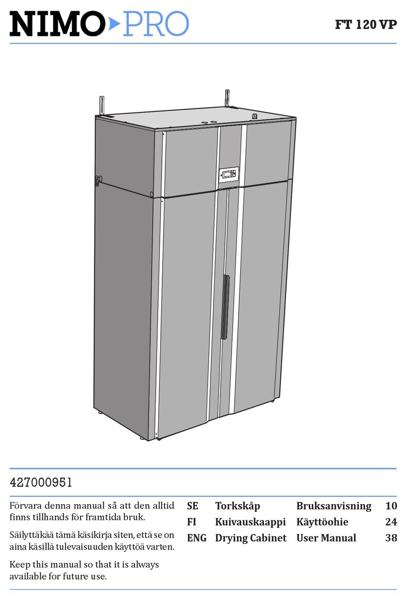
NIMO ECO Dryer 2.0 HP User manual

ECO DRYER 2.0
HELLO
ECO Dryer 2.0 HP
FT 60 VP
Service manual
427000889
ENG Drying Cabinet Service Manual
Keep this manual so that
it is always available for
future use.

ECO Dryer 2.0 HP
Article and serial number
Manufacturer: NIMO-VERKEN AB
Box 124
S-548 22 HOVA
Tel +46 (0)506 / 488 00
Fax +46 (0)506 / 488 10
www.nimoverken.com
Doc. No: 427000889 Rev. 02
Right to make changes reserved.
Printed on environmentally friendly pa-
per meeting the requirements of Friends
of the Earth Sweden and the Swedish
Society for Nature Conservation.
This service manual
The contents of this service manual describe the programming function of the dryer, such as
activation/deactivation of programming mode and parameter adjustment.
The manual also contains instructions for rehanging the door and disassembling the dehu-
midier unit.
For a description of the drying cabinet, see the Installation and User Manual.

3
Service manual
1 The drying cabinet 4
2 Wiring diagram 5
3 Rehanging the door 6
4 Dehumidier unit – disassembly 9
5 Programming 11
5.1 Control panel 11
6 Drying programmes 12
6.1 Selection of drying programme 12
7 Drying function 13
7.1 Start the drying programme 13
7.2 Stop the drying programme 14
7.3 The door is opened 14
8 Setting of drying programme 15
8.1 Introduction 15
8.2 Procedure 16
8.3 Resetting to factory setting 16
9 Trouble-shooting 17
10 Error code list 22
Contents

4
Service manual
Wall attachment
Extendable hanging
sections (3x)
Door hangers
Detachable shoe rack
Tank for condensation
water
Dehumidier unit
Adjustable feet (4x)
1 The drying cabinet

5
Service manual
PUMP
LARGE FAN
SMALL FAN
COMPRESSOR
-X0
-C1
-XM1.0
-XM1.1
-XM1.2
-XM1.3
-M1
-M2 -M3 -M4
-XM2
-XM3.1
-XM3.2
-XM4.2
-XM4.1
-A2 -A3
-S1
-S2
-S3
-XS1.1
-XS1.2
-XS2.1
-XS2.2
-XM2.1
-XM2.2
-XM2.3
Heater
Lamp
Fan
Pot Free 1
Pot Free 2
11
-XDP1
-XS3.1
-XS3.2
-XUP.P
-XUP.P.1
20
21
22
23
N
X12
-XA1.X3.4
-XA1.X3.2
-XA1.X3.3
-XA1.X4
-XA1.X5
-XA1.X6
-XA1.X7
Grounding screw Panel
PE
Grounding screw
Cabinet
PE
30
1
-X1.1 -X1.2
1
2
3
3
4
17
18
19
PE
N
L
-XA1.N1
-A1
N
-XA1.N
-XA1.L
L
Outlet RHx Door User panel
22 43
1
22 3 4 5
25 28
24
-XDP2
26 27
29
+5V
X4 X5 X6 X7
X3
6
5
4123
11
14 15 16
10
12
13
4 3 21
8
7
-XC1.1
-XC1.2
-XC1.3
9
2
X9 X25 X11 X17
Wiring diagram 106159-0
2 Wiring diagram

1
2
3
4
5
6
Service manual
The picture illustrates rehanging from right-
hung to left-hung
3 Rehanging the door
The cabinet is supplied from the factory either right-hung or left-hung. The door can be subse-
quently rehung.
A rehanging kit is needed to rehang the door. This can be ordered as a spare part.
Rehanging kit
pSplice connectors for cables.
pNew cable with plastic bushing.
pUpper hinges, 1 right and 1 left.
1Detach the cabinet from the
wall and turn it to gain access
to the rear.
2Detach the three screws (1)
holding the cover as illustra-
ted and disassemble the lid.
3Carefully lay the cabinet on its
back.
4Remove the cover (2) of the
upper hinge and release the
door cable (3) and detach
the cable from the coupling
(4). Disassemble the upper
hinge (4) which is attached by
two screws. Carefully pull the
hinge away from the cable.
The hinge is provided with
a slot where the cable is th-
readed in or out.
5Lift the door away from the
drying cabinet
Upper hinge

6
7
8
7
Service manual
6Lay the door down carefully with the inside facing
up. Detach all the screws holding the upper panel in
position. The screws are underneath the magnetic
strips.
Remove the hangers and lift o the panel together
with the magnetic strip.
7Press out the plastic bushing (6) in the
door and cut it apart. Then draw the cable
through the hole in the door.
8Fit the connector (7) with the two-sided
tape and t the old cable in the connector.
See illustration.
Fit the new cable (8) with the plastic bush-
ing on the new hinge side and t one end
to the splice connector.To make it easier to
pull the cable it may be necessary to loosen
the upper styrofoam disc.
9Ret door panel and hanger. Take care to
ensure that the magnetic strip ends up in
the right place.
Door with removed inner panel and
magnetic strips
Fit the old
cable here

9
8
Service manual
10 Move the lower hinge (9) to the other side. The hinge
must be inverted and the hinge pain unscrewed and
retted on the other side of the hinge.
Make sure that you tighten the hinge pin properly.
11 Lay the door on the cabinet and take the new upper hinge and carefully
thread in the new cable. Fit the hinge and the protective cover. Connect
the cable to the splice connector in the roof.
12 Raise the cabinet to the upright position and ret the cover.
13 Position the cabinet and secure it to the wall.
14 Wait at least one hour before using the cabinet again, to allow time for
the oil in the compressor to run back. The compressor may otherwise be
damaged.
Lower hinge

1
9
Service manual
Dehumidication unit
4 Dehumidier unit – disassembly
The dehumidication unit
consists of an enclosed
unit in the lower part of
the cabinet.
The whole unit has to be
pulled out for servicing.
From the rear
1Detach the cabinet from the wall
and turn it to gain access to the
rear.
2Unscrew 3x screws (1). The screws
have Torx T40 heads.

2
3 5
4
10
Service manual
The door switch (3) is tted in the
front panel (4).
See illustration on page 21.
After servicing has been com-
pleted, refit the unit to the
drying cabinet in the reverse
sequence.
After the cabinet has been
moved into position, it is
very important that it is
secured to the wall.
From the front
3Remove the shoe rack and disconnect the lter holder.
4Remove the cover plugs and detach the front panel which is attached with 2x screws (2)
(Torx T20). Disconnect the door switch cable (3).
5Detach the mains lead and the communication cable.
6Remove the water container.
7Unscrew the guide (5) for the water tank. One screw holds the guide in place.
8Pull out the dehumidier unit.

ECO DRYER 2.0
HELLO
BUTTONS
The user interface has 4
touch buttons as above.
ARROW UP, increase values or
move in one direction between
the programmes.
ON / OFF START/STOP, start and stop the
programme.
OK, conrm selection and go to next
menu level
ARROW DOWN, reduce values or move in one
direction between the programmes.
11
Service manual
5 Programming
5.1 Control panel

12
Service manual
6 Drying programmes
Chapters 6, 7 and 8 also appear in the User Manual
The drying cabinet is equipped with two automatic programmes:
pNORMAL DRY
pEXTRA DRY
The automatic programmes switch the drying process o automatically when the items of
clothing are dry.
6.1 Selection of drying programme
pNORMAL DRY– Used for drying of garments of normal thickness
pEXTRA DRY – Used for drying of thicker garments, deep drying

13
Service manual
7 Drying function
7.1 Start the drying programme
pLast used drying programme
Press the ON/OFF switch to the “ON” position, indicated by the display lighting up and
showing the last run programme.
After a few seconds the display will show the last run programme. If this is the programme
you want, press START/STOP.
Or choose another drying programme by stepping up or down.
Then start the drying programme with the START/STOP button.
pDoor open
If the door is open when the drying programme is started and the START/STOP button is
activated, the display shows “CLOSE DOOR”.
Close the door and the selected drying programme will start.
pIn operation
The animated symbol (bar) on the left-hand side of the display indicates that the drying
process is in progress.
pCondensation water tank
If the condensation water tank becomes full, the drying process is immediately discontinued
and the display will show “CHECK WATER TANK”. Empty the water tank and re-start the
drying process.
pCooling
During the cooling period the display shows the text “COOL” and counts down 5 min,
remaining time.
pProgramme end
When the cooling period has ended, the drying process is nished, and the display shows
the text “END” (ashing).
When the START/STOP button is pressed or the door is opened, the current programme
is stopped and the display shows the most recently used programme.

14
Service manual
7.2 Stop the drying programme
To discontinue a drying process in progress, press START/STOP.
7.3 The door is opened
If the door is opened when the drying process is under way, the drying process will continue
for a further 5 minutes. The display will show “CLOSE DOOR” and a programme pause period
of 5 minutes will be counted down.
If the door is closed within this 5 minute period, the drying process continues.
If the door is left open, the drying process is discontinued after 5 minutes and has to be re-
started manually.
If you wish to discontinue the drying process immediately, without a 5 minute period, press
START/STOP.

15
Service manual
8 Setting of drying programme
There are options for optimizing the drying cabinet’s two automatic programmes for best results.
This is done by adjusting parameter values for the automatic programme concerned on the
control panel.
Values are displayed as follows:
The current parameter is shown on the top line of the display, e.g. “P 2071”, the set value of the
parameter is shown on the bottom line.
Changes should only be made if you nd that:
pthe washing is not dried suciently
pthe washing is over-dried – long drying time.
8.1 Introduction
The drying cabinet is equipped with two drying programmes, Normal dry and Extra dry.
Normal dry programme is controlled through moisture sensor.
Extra dry programme is controlled through moisture sensor and a time factor.
The automatic programmes end automatically when the washing is dry.
To decide when the washing is dry, a measured value is compared with a factory-set parameter,
parameter P 2072 for Normal dry automatic programme and
parameter P 2071 for Extra dry automatic programme.
It is primarily these two parameters that are adjusted to optimise the drying process.
p If you nd that washing is not dried suciently in:
Normal dry automatic programme reduce the parameter value for P 2072.
Extra dry automatic programme increase the parameter value for P 2071.
p If you nd that washing is over-dried, long drying time in:
Normal dry automatic programme increase the parameter value for P 2072.
Extra dry automatic programme reduce the parameter value for P 2071.
Optimisation of the drying process must always take place in small steps, start by adjusting the
parameter concerned by 1-2 units up or down, then check the result after the next drying process
and if appropriate make a further adjustment.

16
Service manual
8.2 Procedure
1Make sure that the main ON/OFF switch of the drying cabinet is in the OFF position. The
display is not lit.
2Hold down the UP and DOWN buttons and press the main ON/OFF switch to the“ON”posi-
tion. The display lights up and shows the parameter “P105” and the factory preset value of
P105. The row containing the parameter concerned ashes on the display.
3Step through to the parameter concerned by pressing the ARROW UP or DOWN button
repeatedly. If you go too far, all you need to do is to continue stepping forward until the
display shows the correct parameter.
4When the display shows the correct parameter, e.g. “P2072”, press START/STOP to conrm
parameter selection. The row now ashes with the set value of the parameter.
5Increase or reduce the parameter value using the ARROW UP or DOWN buttons.
6To save the set value, press START/STOP.
7 To return to the operating value, press the ARROW DOWN and START/STOP.
8.3 Resetting to factory setting
1Go to parameter display mode as described in 1-2 above.
2Hold down the ARROW UP and ARROW DOWN buttons and press START/STOP. The factory
buttons will be saved and the display will show the most recently run programme.

17
Service manual
Questions Action
The drying cabi-
net does not work
1. Check that the mains lead is connected to a socket.
2. Check that no fuse has blown.
3. Have you pressed the start button?
4. Is the door closed?
5. Is the water tank in position and empty?
The display shows
CHECK WATER TANK
See illistrations
1. Empty the water tank
2. Check that the cover is tted so that the oat arm protrudes out of the
opening in the lid and that the arm runs freely.
3. Check that the water tank is turned so that the oat arm is inside the
box.
4. If none of the above work, the safety switch for a defective pump may
have been activated.
5. Turn o the power supply.
6. Take out the shoe rack.
7. Take out the lint lter.
8. Check whether there is water in the tray. If so:
9. Check that the drain hose is not caught or bent so that a kink has
developed or the hose runs at too steep an angle to the drain without
forming a “trap”.
10. Loosen the grille over the tray which is attached with 2xTorx 40 screws.
11. Loosen the panel holding the protector over the pump. Attached with
1x Torx 40 screw.
12. Remove the Styrofoam protector over the pump.
13. Detach the panel holding the microswitch and moisture sensor, which
is attached with 1x Torx screw and take out the oat.
14. Mop up the water with a sponge or rag.
15. Ret and check that the microswitch has a small gap from the oat of
1-3 mm.
16. Ret other parts.
17. Connect the power supply and test-run the cabinet, the pump should
start to pump immediately.
18. If the problem persists, the whole unit must be replaced.
9 Trouble-shooting

18
Service manual
Questions Action
The display shows
CLOSE DOOR
See illustrations
1. Check that the door seals tightly so that the door switch is activated.
(Located at the bottom of the cabinet on the cover panel in front of
the heat pump unit).
2. If necessary try to tape down the switch and check whether the war-
ning disappears in the display.
3. If none of the above work, disconnect the power supply and disas-
semble the front panel (see description in Chapter 4 Dehumidier unit
disassembly).
4. Check that the cables to the door switch are intact and properly con-
nected. It is seated with 2x cable lugs towards the door switch and
one contact in the tray.
5. If the problem persists, the door switch is probably defective and needs
to be replaced.
6.
Detach the lock washer and press the door switch out from the front panel.
7. Assemble in the reverse sequence.
The display shows
an alarm/error
code
This should normally never happen, but if an alarm or error code appears,
rst try to reset the alarm by holding down the START/STOP button for
5 sec.
If the problem persists, use the list of error codes on page 22 to try to locate
the error. Try to deal with the error indicated, but if the error persists, the
whole unit (heat pump box) must be replaced.
Drying takes a
long time
1.
Clean the cleaning lter (this should preferably be done after each drying).
2. Check that the water tank is empty.
3.
Check that the correct programme has been selected for the type of washing.
4. Check that the washing is not very wet (poorly spun).
5. Check that too much washing has not been hung up.
The washing does
not become dry
1.
Check that the correct programme has been selected for the type of washing.
2. Check that too much washing has not been hung up.
3. Adjust the parameters 2072 and 2071 as described in the section on
parameter adjustment.
The sealing strip
does not close
tightly, the door
is ajar
1. Check that the cabinet is level. Check with a spirit level, adjust with
the adjustable feet if necessary.
2. Check that the cleaning lter and its holder are correctly tted. The
holder should be pressed down towards the heat pump unit beneath
and locked with the rotatable locking angles to seal properly.

19
Service manual
This side forward
Float in water tankWater tank with lid
removed
Fixing screw
for grille
Grille over cover after
shoe rack and lint lter
have been removed

20
Service manual
Attachment for
microswitch and
moisture sensor
Styrofoam protection and
xing plate
Float
The Styrofoam protection
and xing plate have been
removed here
Styrofoam protection
over pump
Fixing plate
Other manuals for ECO Dryer 2.0 HP
1
Table of contents
Other NIMO Dryer manuals

NIMO
NIMO Easy Dryer 1700 User manual

NIMO
NIMO ETS 1500 E User manual

NIMO
NIMO FT 120 VP User manual

NIMO
NIMO ETS 1500 User manual

NIMO
NIMO KM 80 User manual

NIMO
NIMO ECO Dryer 2.0 HP User manual

NIMO
NIMO PRO FT 120 VP User manual

NIMO
NIMO ETS 1700E User manual

NIMO
NIMO KM 80 User manual

NIMO
NIMO Easy Dryer 1900 User manual
Popular Dryer manuals by other brands

ffuuss
ffuuss eos user manual

KitchenAid
KitchenAid 53-3498 installation instructions

Schulthess
Schulthess Spirit topLine TW 8340 operating instructions

Whirlpool
Whirlpool LGR4624BW0 parts list

World Dryer
World Dryer AirMax D M5-972A manual

Alliance Laundry Systems
Alliance Laundry Systems ADEE9BSS user guide