10 ENGLISH
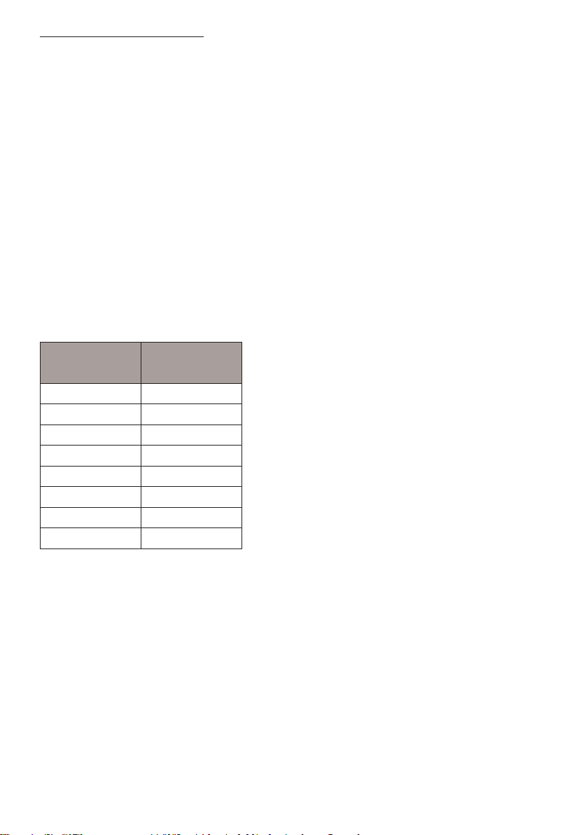
4.4.2 Parameter list
Parameter Name Value Meaning
P105 Language 0
1
2
3
4
5
6
7
English
Swedish
Norwegian
Danish
Finnish
-
French
German
P114 Filter alarm On/O 0
1
O
On
P115 Child lock On/O 0
1
O
On
P2011 Min. drying time Aut 40° 35 min. The drying process will run for min. 35 min. regardless of
the humidity level.
P2012 Max. drying time Aut 40° 180 min. The drying process will run for max. 180 min. regardless of
the humidity level.
P2013 Max. temp. Aut 40° 51° The heating elements will be turned o if this value is
exceeded.
P2014 Outlet temp. process n-
ished. Aut40°
44° The Normal programme will end the drying process with
a cooling period.
For the Extra programme, the extra drying time will start.
P2015 Extra drying time Aut40° 30 min. Drying time for the Extra programme when the outlet temp.
has been reached.
P2021 Min. drying time Aut 60° 35 min. The drying process will run for min. 35 min. regardless of
the humidity level.
P2022 Max. drying time Aut 60° 180 min. The drying process will run for max. 180 min. regardless of
the humidity level.
P2023 Max. temp. Aut60° 76° The heating elements will be turned o, if this value is
exceeded.
P2024 Outlet temp. process n-
ished. Aut 60°
60° The Normal programme will end the drying process with
a cooling period.
For the Extra programme, the extra drying time will start.
P2025 Extra drying time Aut 60° 30 min. Drying time for the Extra programmewhen the outlet temp.
has been reached.
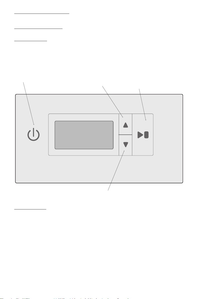
4.4 Optimizing the drying programme
4.4.1 Introduction
The automatic programme of the drying cabinet can be optimized with the control panel buttons,
when the drying cabinet is in programming mode.
Only make adjustments, if:
p the laundry is not dry enough
p the laundry is being dried for too long - long drying time