CDI FLEXIBLE FURLER 2 Manual

FLEXIBLEFURLER2
INSTALLATION/OPERATINGINSTRUCTIONS
277BakerAvenue / PO Box 1250, Concord, MA01742
Tel: 978-371-5508 Fax: 978-371-5597
Web: www.sailcdi.com
November 2001

WARNINGS
Improper installation of the Flexible Furler or improper
reinstallation of the forestay can cause failure of the forestay,
and could result in the loss of the mast and injury to crew
members.
Before installation, check that toggles are used at both ends
of the forestay. Improper toggling may cause the forestay to
fatigue due to bending stresses.
After installation, check that all clevis pins and cotter pins
removed during installation are replaced. specially check that
all turnbuckle pins are in place. Make sure the turnbuckle
threads have full engagement. Check for free rotation of the
unit, paying particular attention that the luff or the inside of the
drum does not touch the turnbuckle body. If it touches, furling
may unscrew the turnbuckle. Insure that the bearing is not
jammed, as winching with a jammed bearing will transmit
torsional loads to the turnbuckle which could lead to failure.
Check to insure that at least 3" clearance exists to the side and
above the halyard top fitting.
During operation, never winch the unit without checking for jams
or snarls. Winching against an obstruction can sever or cause
hidden damage to your forestay. Keep your unused halyards
flipped to the after side of your spreaders. If the unit becomes
hard to furl, investigate and correct the cause. Failure to do so
can lead to the failure of the forestay.
The Flexible Furler is NOT designed to be used while your
boat is in the water and passing under low clearance
obstructions (bridges, power lines, etc) with mast is tipped
forward and headstay attached to the bow. Lowering the mast
in this manner is dangerous even without a furler, and can be
further complicated by the weight of the furler and the sail.

(1)
INDEX
Warnings . . . . . . . . . . . . . . . . . . . . . . . . . . . . . .Inside Front Cover
Specifications . . . . . . . . . . . . . . . . . . . . . . . . . . . . . . . . . . . . . . . 1
Drawing . . . . . . . . . . . . . . . . . . . . . . . . . . . . . . . . . . . . . . . . . . . . 2
Parts List . . . . . . . . . . . . . . . . . . . . . . . . . . . . . . . . . . . . . . . . . . . 3
Uncoiling and Straightening the Luff . . . . . . . . . . . . . . . . . . . . 4 - 5
Assembly . . . . . . . . . . . . . . . . . . . . . . . . . . . . . . . . . . . . . . . . . 5 - 8
The Furling Line . . . . . . . . . . . . . . . . . . . . . . . . . . . . . . . . . . . . . 9
Hoisting the Jib . . . . . . . . . . . . . . . . . . . . . . . . . . . . . . . . . . . . . 10
Lowering the Jib . . . . . . . . . . . . . . . . . . . . . . . . . . . . . . . . . . . . 10
Sailing with Your Furler . . . . . . . . . . . . . . . . . . . . . . . . . . . . 11 - 12
Maintenance . . . . . . . . . . . . . . . . . . . . . . . . . . . . . . . . . . . . . . . 12
Trailering Instructions . . . . . . . . . . . . . . . . . . . . . . . . . . . . . . . . 12
Sailmaker's/Rigger's Instructions . . . . . . . . . . . Inside Back Cover
Warranty . . . . . . . . . . . . . . . . . . . . . . . . . . . . . . . . . . . Back Cover
SPECIFICATIONS
Forestay Length 29 feet, maximum
Wire Size 1/8", 5/32", 3/16"
Forestay Fittings There should be a toggle at both ends of the
forestay (see second paragraph under
Warnings above). The turnbuckle should be
a 1/4"
or 5/16" swage-on turnbuckle with
T-bolt and toggle at bottom (see, page 5).
Mounting System can not be mounted above
turnbuckle. If you wish to raise system for
better clearance, shorten stay and use
linkplates below the turnbuckle.
Furling Line 5/32" or 3/16" dacron. If you prefer a larger
diameter, you can de-core larger double
braid line forward of the cockpit, thereby
reducing the diameter as it winds on the
drum.

(2)

(3)
PARTS LIST
ALuff . . . . . . . . . . . . . . . . . . . . . . . . . . . . . . . . . LFF2
BSpool Assembly . . . . . . . . . . . . . . . . . . . . . . . 2010
CLuff Support Pin (3/16" x 1-1/2") . . . . . . . . . . 2009
DHalyard Anchor Pin . . . . . . . . . . . . . . . . . . . . 1998
Halyard Anchor Shackle . . . . . . . . . . . . . . . . 2007
EMain Bearing . . . . . . . . . . . . . . . . . . . . . . . . . 1033
FCup (Stainless Steel) . . . . . . . . . . . . . . . . . . . 1807
GAntirotation Strap . . . . . . . . . . . . . . . . . . . . . . 1081
HFerrule (part of halyard) . . . . . . . . . . . . . . . . . - - - -
JHalyard Top Fitting . . . . . . . . . . . . . . . . . . . . . 2011
KHalyard Assembly (1/4" x 33') . . . . . . . . . . . . 1932
LTack Tension Line (1/8" x 4') . . . . . . . . . . . . . 2048
MThrust Washer . . . . . . . . . . . . . . . . . . . . . . . . 1253
NTack Tension Pin . . . . . . . . . . . . . . . . . . . . . . 1998
TackTension Shackle . . . . . . . . . . . . . . . . . . 2007
Not Shown
Instruction Manual . . . . . . . . . . . . . . . . . . . . . 1049

(4)
UNCOILING AND STRAIGHTENING THE LUFF –
PLEASE READ CAREFULLY!
If you received the luff coiled,
BE CAREFUL
while cutting the tape
that holds the luff coiled.
THE LUFF CAN UNCOIL WITH
CONSIDERABLE FORCEAND CAUSE INJURY.
Start removing the tape by cutting the band retaining the outside
end of the coil while holding the straight portion. Gently uncoil to
the next band of tape. Repeat this process until all tape has been
removed. When cutting the last piece of tape, the coil will have a
tendency to spring outwards so be cautious. Never cut the tape
restraining the inner end first as the coil will spring open when the
last tape is cut.
When the tape is removed, the luff will still be curved. To
straighten, you will need three people. NEVER try to straighten by
laying luff on the ground and weighting it down along its length. IT
WILL TAKE AYEAR! Rather, with one person at each end and the
others spaced along the luff, recoil the curved portion in one large
loop in the opposite direction. Note that the lower end from the
sail feed slot to the bottom was shipped straight and should not be
recoiled (see drawing above left).

(5)
After coiling in the opposite direction, tape the upper end to the
lower portion above the sail feed slot (see drawing previous page,
right) leaving the straight portion free. Leave the coil re-coiled for
several hours, a minimum of three if it’s warm, longer if it’s cold.
After this time, carefully cut the tape and check the straightness.
The luff does not need to be perfectly straight as a tight forestay
will finish the job.
Clean the luff with a rag soaked in paint thinner. For deep
scratches and ground in dirt, rub with a rag soaked in acetone. Be
cautious, however, as prolonged exposure to acetone will destroy
the luff.
ASSEMBLY
Assembly is easiest with the mast down although it can be done
with the mast up (see instructions below).
Assembly of Luff Extrusion, Halyard Top Fitting and Halyard
1. Measure the pin to pin length (L below) of the forestay with the
turnbuckle in its normal state of adjustment. If the mast is up, you
will have to raise a tape on the jib halyard and add an amount
approximately equal to the distance from the top end of the tape to
the pin at the top of the forestay. Cut off the top end of the luff so
that the total luff length is 12 1/4” less than the measured pin to
pin length.

(6)
2. The Flexible Furler uses a built-in 1/4” rope halyard instead of
your boats halyard. One end of the halyard has had the rope core
removed leaving only the outer braid while the other end has both
core and braid intact. The de-cored end is closest to the metal
ferrule. To install, insert the intact end into the cavity in the halyard
top fitting and through the off-center curved hole until the halyard
exits from the “nose” on the halyard top fitting. Pull the halyard
through until the ferrule is about a foot from the halyard top fitting.
3. Pass the decored section of the line through the top of the
groove in the luff extrusion opposite the groove with the sail feed
slot (see photos below). Push the ferrule an inch down into
groove. You should now be able to pull on the decored section of
the halyard and have the ferrule slide inside the groove. Don’t do
this until you’re ready to raise the sail. Fit the halyard top fitting
over the top of the luff with the halyard exiting the side of the
halyard top fitting over the groove with the sail feed slot. Tighten
locking screw. Tie a messenger line, the length of the luff, to the
decored end of the halyard. This line will be used to raise the sail.
4. Completely unscrew the swage-end of the turnbuckle and
T-bolt and toggle from the turn buckle body (see page 5 for
terminology).
5. Pass the swage-end and wire down through the halyard top
fitting/luff extrusion assembly. If the mast is stepped, first pass a
light line through the center hole of halyard top fitting/luff assembly
for the full length of the luff. Make the upper end of that line fast to
the cotter pin hole in the swage-end of the turnbuckle using a
piece of wire to make the link. Pull on the light line while pushing
the luff up the forestay. When the swage-end and wire appear,
screw on the turnbuckle body to prevent the luff from sliding down.

(7)
Assembling the Cup, Bearing and Antirotation Strap
6. If your forestay turnbuckle screw is 5/16” in diameter, drill out
the center hole of the bearing with a 21/64” drill.
7. Place the antirotation strap between the two sides of the
toggle.Add enough 5/16” spacer washers on the T-bolt so when
the antirotation strap is up against the bottom of the T-bolt or cross
bar, the washers are just under the top of the antirotation strap
(see photo at left below). Push the T-bolt through the center hole in
the cup and the bearing (see photo at right below). Screw in the
two pan head screws through the antirotation strap, cup and into
the bearing. Refer to page 9, ‘Bringing the Furling Line Aft” to
select the correct pair of holes.
8. Slide the spool over the turnbuckle body and luff. Insure thrust
washer (part M, a 1 3/4” flat stainless washer) is in place inside
the bearing cavity. Screw the T-bolt into the turnbuckle body until
the overall forestay length is correct. Replace both cotter pins.
Note: final adjustment of the turnbuckle can be done after the
installation is complete (see below).
Final Assembly
9. Step the mast (if unstepped), attach the forestay to the
chainplate. Tension rig using backstay turnbuckle or upper shrouds
(if there is no backstay).
T-bolt/toggle with spacer washers
and antirotation strap in place Assembling cup, bearing
and antirotation strap

(8)
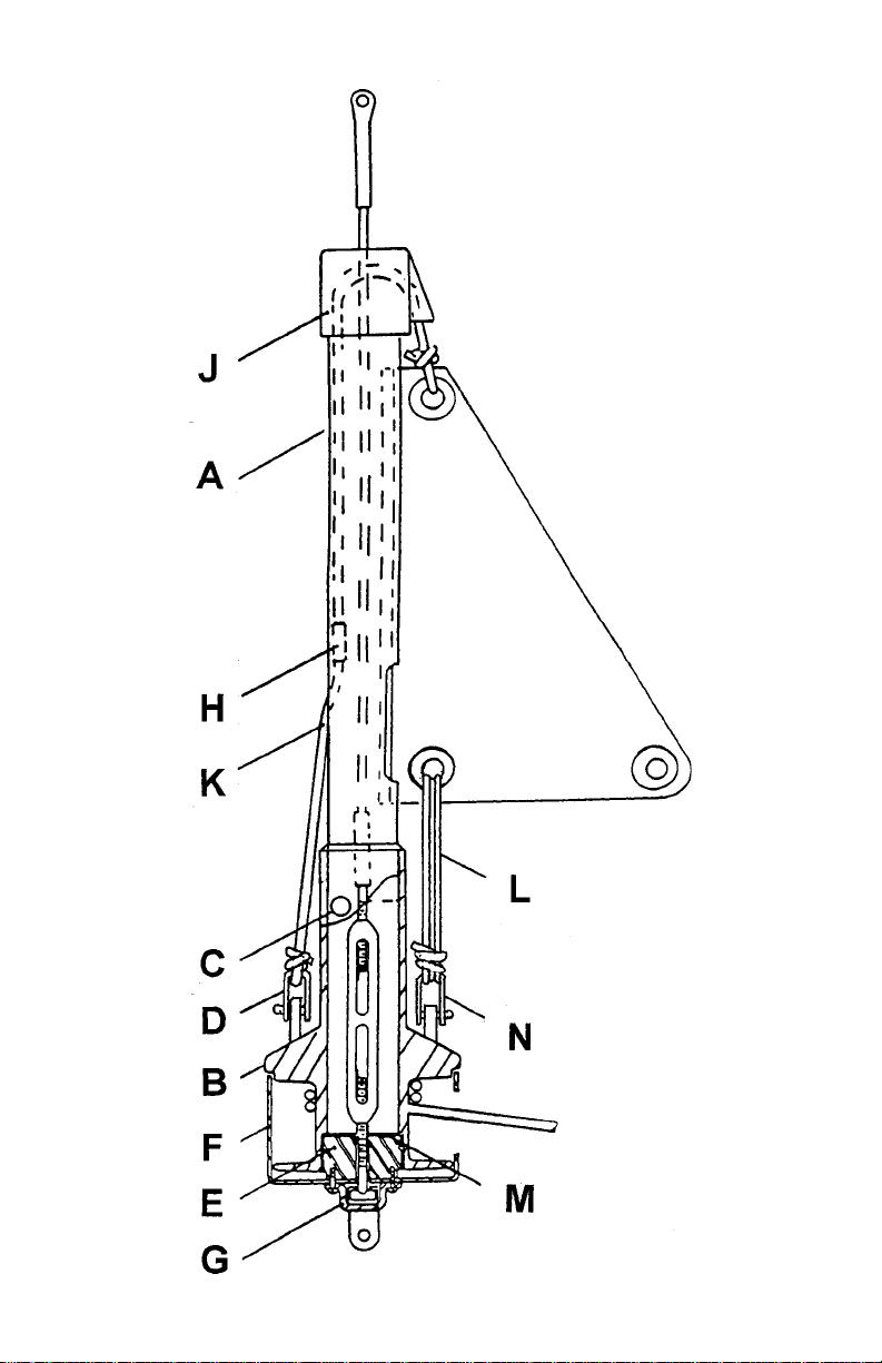
10. Slide the spool body down the luff, into the cup and over the
main bearing, insuring thrust washer is in place. Lift the luff up off
the turnbuckle body, insert the luff support pin through the hole in
the spool throat. The luff rests on top of this pin.
CAUTION:
the luff
must not sit on the turnbuckle body as turning the furler might
unscrew the turnbuckle causing dismasting.
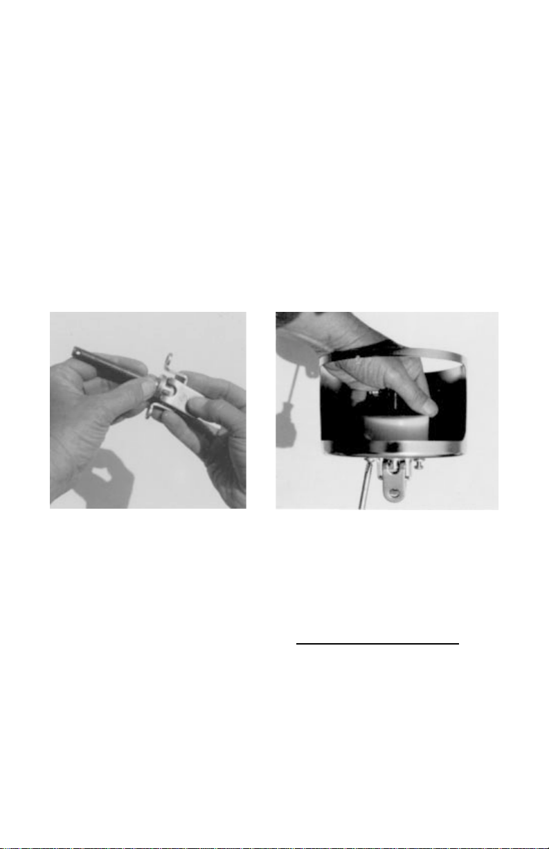
11. Pass the furling line through the opening in the side of the
cup, then up through the hole in the top of the spool flange. Tie an
overhand knot to prevent it from escaping. Before raising jib, rotate
the furler so there are about 20 turns of furling line on the spool.
This will be finished off later.
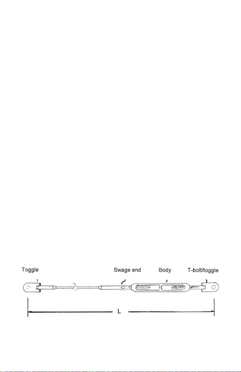
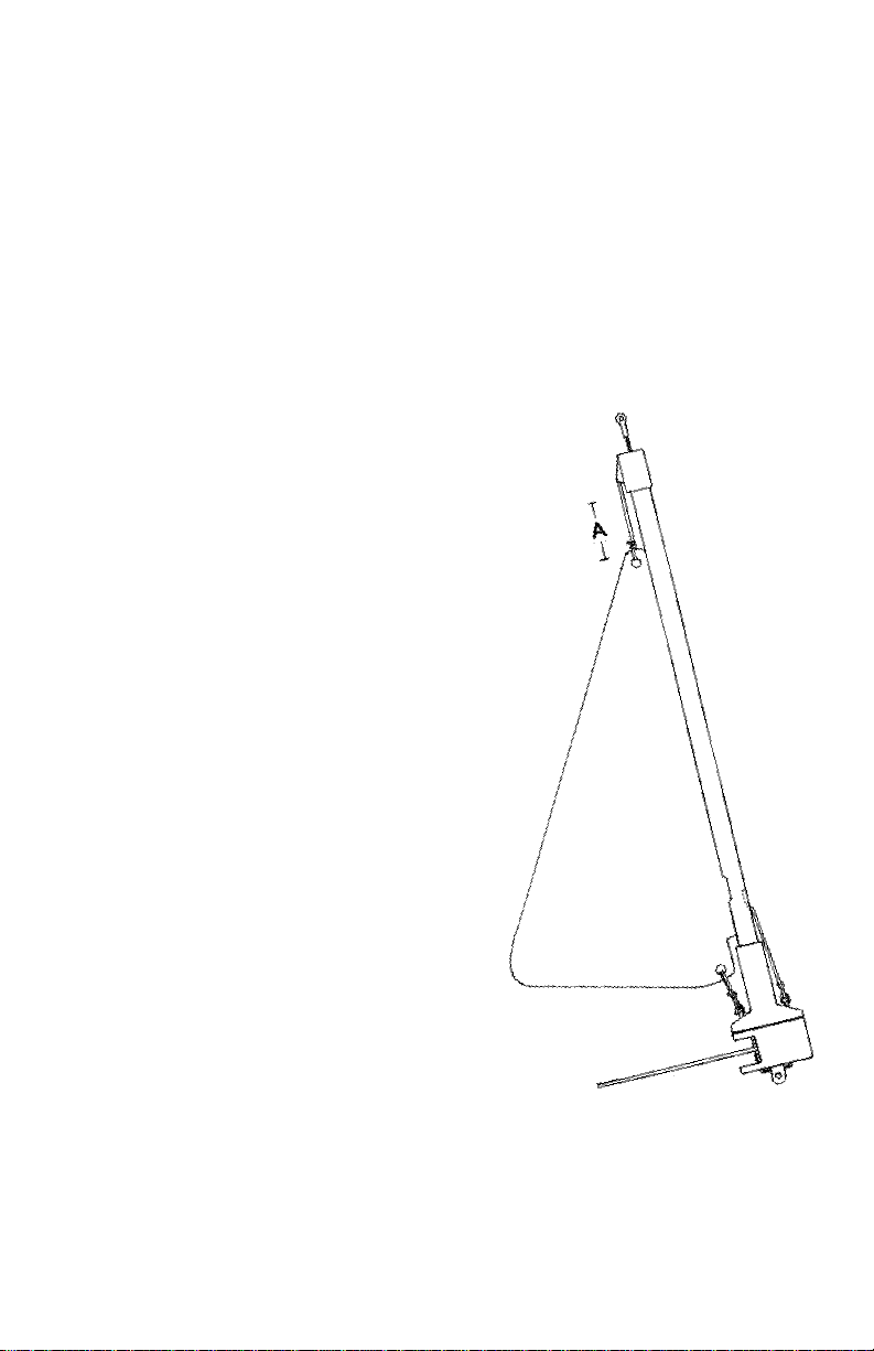
12. If your jib is full or almost full hoist
(dimension A in drawing at right is less than
12” when sail is in desired position), pull the
halyard ferrule hard up against the halyard
top fitting and cut the halyard so that when
it is tied to the sail, the head of the sail is
just below the sail feed slot. Melt end of
rope to prevent fraying.
If dimension A is more than 12” when jib
is hoisted to desired position, pull the
halyard ferrule up against the halyard
top fitting and tie the halyard to the
sail so the head of the sail is below
the sail feed slot by an amount
approximately equal to dimension A.
When the sail is raised, there must
enough decored halyard to reach
and be made fast to the halyard
anchor shackle. This may take some
experimentation so cut the halyard
only after you confirm the length.
13. If the forestay length needs to be adjusted, remove the luff
support pin, slide up the spool to expose turnbuckle and make
your adjustment. In so doing, you may knock out the thrust washer.
After adjusting the turnbuckle, be sure thrust washer is in place.

(9)
THE FURLING LINE
(Please read carefully)
1. Position the first fairlead so the furling line exits the cup at
right angles to the forestay and approximately in the middle of the
cup athwartships. Failure to properly position this first lead will
result in chafing of the furling line. In most cases, the first fairlead
must be mounted on the deck. Properly bed the screws.
2. The orientation of the cup is determined by the two holes in
the bottom of the cup you select to mount the antirotation strap to
the cup and bearing (see 5, page 7) and the orientation of the
chainplate. Most often, the cup is mounted such that the hole for
the furling line is facing aft. If you wish to position the first lead at
or near the rail, you may have to turn the cup 45 degrees to the
centerline. This may be done by selecting holes on the diagonal
when installing the antirotation strap.
3. Continue the furling line aft toward the cockpit using as many
or as few leads as you wish. Try to avoid large angle changes with
the furling line as such angle changes rapidly increase the force
required to furl the sail even when using low friction blocks.
4. Place a cleat near the cockpit away from other sail handling
equipment. When the sail is furled, there’s a lot of line to stow.
5. The system is designed for 3/16” dacron line. Make sure you
have enough to completely furl your largest sail plus about five
turns. This will allow you to furl an extra tight furl in heavy winds
and still have a couple of turns left. Before hoisting sail for the first
time, wind about 20 turns on the spool.
Locating the first fairlead

(10)
HOISTING THE JIB
1. Attach the halyard to the jib.
2. Pull up the sail by pulling down the decored end of the halyard
using the messenger line attached to the decored end (see #3,
page 6), while feeding the sail into the sail feed slot. If raising and
lowering the sail frequently, a pre-feeder should be added.
3. When the sail is fully hoisted, untie the messenger line. Pass
the decored end of the halyard through the halyard shackle on top
of spool and finish off with bowline or some half hitches.After
taping rope to prevent fraying, cut off the unused decored end.
Melt end and remove tape.
4. Tension the luff of the sail with the 1/8” tack tension line,
passing two or three parts through the downhaul shackle on spool
flange and grommet on sail, and finish off with some half hitches.
5. Add or eliminate furling line on drum as necessary. When sail
is furled tightly, there should be two or three turns left on the spool.
LOWERING THE JIB
1. Ease off the tack tension line.
2. Castoffthehalyardfromthehalyard shackle.Attach amessenger
line to the decored end of the halyard and lower the jib.

(11)
SAILING WITH YOUR FURLER
The Flexible Furler is a set-it-and-forget-it furling and reefing
system. It requires no maintenance although keeping the bearing
clean is a good idea. The jib requires only enough tension to
remove the wrinkles along the luff of the sail. This tension will be
quite low (less than 50 pounds) because modern sails are quite
stiff requiring little stretching and because the luff tape will prevent
scalloping often encountered with hank-on sails. This allows the
sail to be set up for the entire season without need for adjustment
before and after each use.
Controlling draft by varying the luff tension is effective only with the
sail fully deployed. If you are sailing to windward frequently in
heavy weather and reef frequently, it may be appropriate to have a
foam tape installed which will help remove the belly in a reefed
sail. We suggest you consult your sailmaker.
When sailing reefed, you must move the jib leads forward to
maintain the proper sheet angle. Failure to do so will give poor sail
shape and could cause the furler to rise off the bearing.
To furl or reef ease the sheet and pull the furling line until you
reach the amount of sail you wish left deployed. Cleat down the
furling line. Note: letting the sheet run free while furling may make
furling a little easier but will result in an uneven furl.

(12)
To unfurl or unreef, ease the furling line while trimming the sheet.
Always keep some tension on the furling line to insure a smooth
wrapping of the furling line on the drum.
In certain conditions, you may wish to use a winch to get the
furling started. Be careful that there is no extraneous ship’s
halyard wrapping in the furler while you winch as this could
eventually jam the furler and/or damage the headstay. Always look
up at the top of the furler while winching, stop and clear anything
that snarls. Furling should not get any more difficult as the sail is
brought in. It should get easier. If it gets harder, stop and
determine why.
Always keep unused halyards flipped aft of the spreaders. Do not
clip them to the bow.
MAINTENANCE
No routine maintenance is required, but an occasional rinsing with
fresh water is a good idea. We do not recommend the use of wet
lubricants (grease) as such lubricants can hold wear causing
particles in suspension. Dry lubricants (teflon sprays, etc.) are fine
to make furling easier.A ball bearing is also available for the
ultimate in easy furling and reefing.
When storing for prolonged periods, it is best to strap the furler
along the mast, supporting the furler to avoid any potential
sagging at the ends as well as in the middle. If coiling for short
periods, do not coil in a radius of less than 3 feet (6 foot diameter).
Do not expose the furler to temperatures in excess of 140 degrees
F. Such temperatures may frequently occur in warm climates
under a boat cover and void the warranty.
TRAILERING WITH YOUR FLEXIBLE FURLER
When trailering, the Furler should be lashed along the mast,
keeping it as straight as possible. The ends must be supported to
keep the luff from bouncing while driving which could lead to the
fatigue failure of the luff.

SAILMAKER’S INSTRUCTIONS
Luff tape required is #6. Sail luff deduction is 13” from pin-to-pin
length.
We recommend use of webbing at the head and tack instead of
metal grommets. This allows the sail to reef and furl more evenly.
The Flexible Furler can not be mounted above the turnbuckle as
this potentially puts excessive torsional stress on the turnbuckle.
This, in turn, could lead to the unscrewing of the turnbuckle and
dismasting. To raise the system, shorten the headstay the desired
amount and install linkplates under the turnbuckle.
The FF2 can only be used with 1/4"
and 5/16” turnbuckles.
Turnbuckle must have threaded swage stud and T-bolt and toggle.
Stays with other fittings at the bottom (eyes, jaws, etc.) must be
altered as the antirotation strap will not fit using these other
fittings. We recommend replacing closed body, lock nut
turnbuckles with open body, cotter pinned turnbuckles. Lock nuts
are not a satisfactory way to lock turnbuckles. Any improper
installation could lead to an unscrewing torque on the turnbuckle
that could lead, in turn, to the loss of the mast.
Toggles are recommended at the top of the forestay as well as the
bottom.

LIMITED 7 YEAR WARRANTY
The Flexible Furler is warranted to remain functional for 7
years from date of purchase. You must be the original
purchaser of the unit. If, during this period, any part
becomes non-functional, CDI will repair or replace it,
free of charge, except for freight.
This warranty covers:
At Sea: winching against obstructions, unseamanlike use,
and dismastings.
In Boatyards: rough and abusive handling. The luff is
warranted even if run over by light vehicles, excluding 3/4
ton pick-up trucks, marine railways and travelifts.
The warranty does not cover:
At Sea: Shipwreck, collision and acts of God. The warranty
is void if the mast is not fixed in place vertically at all times
while the boat is in the water. Tipping the mast forward to
pass under bridges, power lines or other low clearance
instructions voids the warranty.
On Trailers: Collision; being dragged on the ground;
improper stowage resulting in kinks, bends and twists;
thrumming in the wind; and damage due to the luff not being
supported over its entire length.(See trailering instructions.)
Boatyards and/or Storage: Kinks, twists and bends due to
improper storage (see maintenance instructions).
This warranty remains in force for charter and other com-
mercial operations. No maintenance is required to keep the
warranty in force.
Other manuals for FLEXIBLE FURLER 2
1
Table of contents
Other CDI Marine Equipment manuals
Popular Marine Equipment manuals by other brands

GUIDANCE MARINE
GUIDANCE MARINE RadaScan View Installer's guide

Dometic
Dometic Optimus EPS Installation and user manual

Raymarine
Raymarine SPX-5 Installation & setup guide

Wet Sounds
Wet Sounds WS-MC2 owner's manual

AC MARINE
AC MARINE KUM400 Series installation guide

Quick
Quick MC2 Series Installation and use manual