Nokia NPD-4 Series User manual

CCS Technical Documentation
NPD-4 Series Transceivers
Issue 1 02/2003 Confidential Nokia Corporation
Troubleshooting — BB

NPD-4
Troubleshooting — BB CCS Technical Documentation
Page 2 Nokia Corporation Confidential Issue 1 02/2003

CCS Technical Documentation Troubleshooting — BB
NPD-4
Issue 1 02/2003 Nokia Corporation Confidential Page 3
Contents Page No
Troubleshooting Overview ............................................................................................ 5
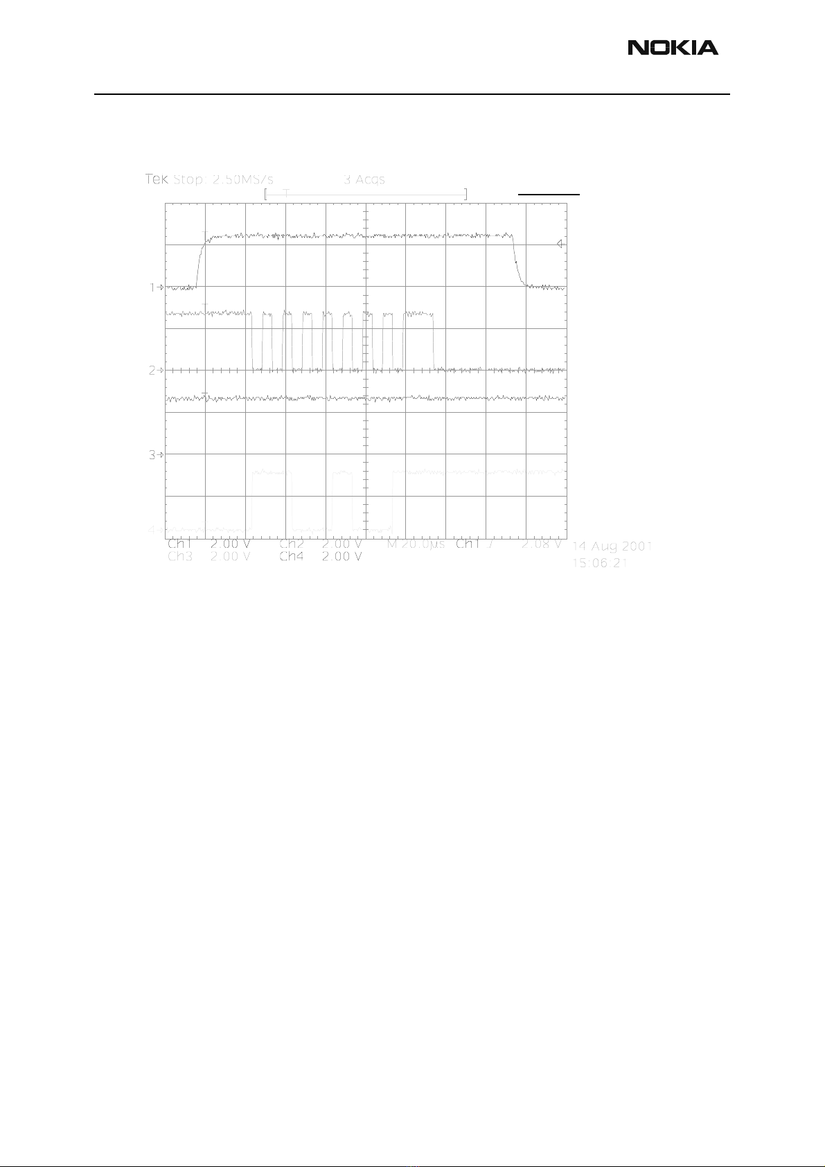
Flash programming ......................................................................................................6
Connections to Baseband.......................................................................................... 6
Baseband Power Up .................................................................................................. 7
Flash Programming Indication.................................................................................. 7
Flashing..................................................................................................................... 7
Power Up and Reset ...................................................................................................10
Power up with PWR key......................................................................................... 12
Power up when charger is connected...................................................................... 12
RTC alarm power up............................................................................................... 13
Power off ...................................................................................................................13
Power Consumption and Operation modes ...............................................................13
Power Distribution .....................................................................................................14
Clock Distribution .....................................................................................................15
RFClk (19.2 MHz Analog)...................................................................................... 15
RFConvClk (19.2 MHz digital) .............................................................................. 16
CBUSClk Interface ................................................................................................. 17
DBUSClk Interface ................................................................................................. 17
SLEEPClk (Digital)................................................................................................. 18
SLEEPClk (Analog)................................................................................................ 18
Charging operation ....................................................................................................19
Battery..................................................................................................................... 19
Charging circuitry ................................................................................................... 20
Charger Detection ................................................................................................... 20
Charge Control........................................................................................................ 21
Audio .........................................................................................................................21
Display and Keyboard ...............................................................................................22
Accessory ...................................................................................................................22
Test Points.................................................................................................................... 23
Troubleshooting/Flowcharts ........................................................................................ 24
Top troubleshooting map ...........................................................................................26
Phone is totally dead ..................................................................................................28
Flash programming doesn’t work ..............................................................................29
Phone is jammed ........................................................................................................30
Power doesn’t stay on or the phone is jammed .........................................................31
Charger ......................................................................................................................33
Audio faults ...............................................................................................................34
Earpiece................................................................................................................... 34
Microphone ............................................................................................................. 35
MIDI........................................................................................................................ 36
Vibra........................................................................................................................ 37
Display faults .............................................................................................................38
Keypad faults .............................................................................................................40
Power key................................................................................................................ 40
UI modules.............................................................................................................. 41

NPD-4
Troubleshooting — BB CCS Technical Documentation
Page 4 Nokia Corporation Confidential Issue 1 02/2003

CCS Technical Documentation Troubleshooting — BB
NPD-4
Issue 1 02/2003 Nokia Corporation Confidential Page 5
Troubleshooting Overview
The baseband module of the NPD-4 transceiver is a CDMA dual mode engine. The base-
band architecture is based on the NHP-2 phone, but includes some additional features,
such as MIDI and gray-scale LCD.
The baseband consists of three ASICs: Universal Energy Management (UEM), Universal
Phone Processor (UPP), and FLASH 64Megabit.
The baseband architecture supports a power-saving function called ”sleep mode”. This
sleep mode shuts off the VCTCXO, which is used as system clock source for both RF and
baseband. While in sleep mode, the system runs from a 32 kHz crystal and all the RF reg-
ulators (VR1A, VR1B, VR2, … VR7) are off. The sleep time is determined by network
parameters. Sleep mode is entered when both the MCU and the DSP are in standby mode
and the normal VCTCXO clock is switched off. The phone is awakened by a timer running
from this 32 kHz clock supply. The period of the sleep/wake up cycle (slotted cycle) is
1.28N seconds, where N= 0, 1, 2, depending on the slot cycle index.
NPD-4 supports standard Nokia two-wire and three-wire chargers (ACP-x and LCH-9).
However, the three-wire chargers are treated as two-wire chargers. The PWM control
signal for controlling the three-wire charger is ignored. Charging is controlled by UEM
ASIC and EM SW.
BLC-2 Li-ion battery is used as main power source. BLC-2 has nominal capacity of
950 mAh.
NPD-4 supports Tomahawk accessories. The system connector for the NPD-4 phones is
the 14-pin Tomahawk connector. The accessories supported include headset (HDB-4),
loopset (LPS-4), basic handsfree car kit (BHF-1), advanced car kit (CARK-142), USB data
cable (DKU-5), and data/flash cable (DKU-5F). The detection is based on the digital ID
read from the accessories.
This service manual also contains a complete troubleshooting guide for GPS circuitry.

NPD-4
Troubleshooting — BB CCS Technical Documentation
Page 6 Nokia Corporation Confidential Issue 1 02/2003
Figure 1: CDMA Block Diagram
Flash programming
Connections to Baseband
The flash programming equipment is connected to the baseband using test pads for gal-
vanic connection. The test pads are allocated in such a way that they can be accessed
when the phone is assembled. The flash programming interface uses the VPP, FBUSTX,
FBUSRX, MBUS, and BSI connections for the connection to the baseband. The connection
is through the UEM — which means that the logic levels correspond to 2.7V. Power is
supplied using the battery contacts.

CCS Technical Documentation Troubleshooting — BB
NPD-4
Issue 1 02/2003 Nokia Corporation Confidential Page 7
Baseband Power Up
The baseband power is controller by the flash prommer in production and in reprogram-
ming situations. Applying supply voltage to the battery terminals, the baseband will
power up. Once the baseband is powered, flash-programming indication is done as
described in the following section.
Flash Programming Indication
Flash programming is indicated to the UPP using MBUSRX signal between UPP and UEM.
The MBUS signal from the baseband to the flash prommer is used as clock for the syn-
chronous communication. The flash prommer keeps the MBUS line low during UPP boot
to indicate that the flash prommer is connected. If the UPP MBUSRX signal is low on
UPP, the MCU enters flash programming mode. In order to avoid accidental entry to the
flash-programming mode, the MCU only waits for a specified time to get input data from
the flash prommer. If the timer expires without any data being received, the MCU will
continue the boot sequence. The MBUS signal from UEM to the external connection is
used as clock during flash programming. This means that flash-programming clock is
supplied to UPP on the MBUSRX signal.
The flash prommer indicates the UEM that flash programming/reprogramming by writing
an 8-bit password to the UEM. The data is transmitted on the FBUSRX line and the UEM
clocks the data on the FBUSRX line into a shift register. When the 8 bits have been
shifted in the register, the flash prommer generates a falling edge on the BSI line. This
loads the shift register content in the UEM into a compare register. If the 8 bits in the
compare registers match with the default value preset in the UEM. The flash prommer
pulls the MBUS signal to UEM low in order to indicate to the MCU that the flash prom-
mer is connected. The UEM reset state machine performs a reset to the system, PURX low
for 20 ms. The UEM flash programming mode is valid until MCU sets a bit in the UEM
register that indicates the end of flash programming. Setting this bit also clears the com-
pare register in the UEM previously loaded at the falling edge of the BSI signal. During
the flash programming mode, the UEM watchdogs are disabled. Setting the bit indicating
end of flash programming enables and resets the UEM watchdog timer to its default
value. Clearing the flash programming bit also causes the UEM to generate a reset to the
UPP.
The BSI signal is used to load the value into the compare register. In order to avoid spuri-
ous loading of the register, the BSI signal will be gated during UEM master reset and dur-
ing power on when PURX is active. The BSI signal should not change state during normal
operation unless the battery is extracted; in this case, the BSI signal will be pulled high,
note a falling edge is required to load the compare register.
Flashing • Flash programming is done by using FBUSTX, FBUSRX, MBUS, and
BSI lines.
• When phone is connected to the prommer, the prommer will first set BSI
to "1" and then uses FBUSRX for writing and MBUS for clocking. The
prommer will indicate to UEM that flash programming will take place by
writing 8-bit password (*0xC9") to UEM after BSI is set to high. After the

NPD-4
Troubleshooting — BB CCS Technical Documentation
Page 8 Nokia Corporation Confidential Issue 1 02/2003
password is checked, BSI is set back to "0”. See the following figure.
Figure 2: Flashing starts by BSI being pulled up and password being sent to UEM
MCU will indicate to prommer that it has been noticed, by using FBUSTX signal. After
this, it reports UPP type ID and is ready to receive secondary boot code to its internal
SRAM. (See the following figure.)
CH1 = BSI
CH2 = MBUS
CH3 = FBUSTX
CH4 = FBUSR
X
Measure points
Production test patte
rn
(J396)
FLASH_1

CCS Technical Documentation Troubleshooting — BB
NPD-4
Issue 1 02/2003 Nokia Corporation Confidential Page 9
Figure 3: Flashing (2)
Ch1-> PURX
Ch2-> MBUS toggled three times for MCU initialization
Ch3-> FBUS_TX low, MCU indicates that prommer has been noticed
Ch4-> FBUS_RX
• This boot code asks MCU to report prommer phone’s configuration
information, including flash device type. Now prommer can select and
send algorithm code to MCU SRAM (and SRAM/Flash self-tests can be
executed). (See the following figure.)
CH1 = PURX
CH2 = MBUS
CH3 = FBUSTX
CH4 = FBUSRX
Measure points
Production test patter
n
(J396)
FLASH_2

NPD-4
Troubleshooting — BB CCS Technical Documentation
Page 10 Nokia Corporation Confidential Issue 1 02/2003
Figure 4: Flashing (continued)
Power Up and Reset
Power up and reset is controlled by the UEM ASIC. The baseband can be powered up in
the following ways:
• By the Power button, which means grounding the PWRONX pin of the
UEM
• By connecting the charger to the charger input
• By the RTC Alarm, when the RTC logic has been programmed to give
an alarm
After receiving one of the above signals, the UEM counts a 20 ms delay and then enters
its reset mode. The watchdog starts up, and if the battery voltage is greater than Vcoff+,
a 200 ms delay is started to allow references and so on to settle. After this delay elapses,
the VFLASH1 regulator is enabled. Then, 500 us later, VR3, VANA, VIO, and VCORE are
enabled. Finally, the Power Up Reset (PURX) line is held low for 20 ms. This reset, PURX is
sent to UPP and resets are generated for the MCU and the DSP. During this reset phase,
the UEM forces the VCTCXO regulator on regardless of the status of the sleep control
input signal to the UEM. The FLSRSTx from the UPP is used to reset the flash during
power up and to put the flash in power down during sleep. All baseband regulators are
switched on at the UEM power on—except for the SIM regulator and Vflash2. Vsim is not
used this moment and Vflahs2 is used for active cover. The UEM internal watchdogs are
running during the UEM reset state, with the longest watchdog time selected. If the
watchdog expires, the UEM returns to power off state. The UEM watchdogs are internally
CH1 = PURX
CH2 = MBUS
CH3 = FBUSTX
CH4 = FBUSRX
Measure points
Production test pattern
(J396)
FLASH_3
Data transfer has
started (Fbus_Rx)

CCS Technical Documentation Troubleshooting — BB
NPD-4
Issue 1 02/2003 Nokia Corporation Confidential Page 11
acknowledged at the rising edge of the PURX signal in order to always give the same
watchdog response time to the MCU.
The following timing diagram represents UEM start-up sequence from reset to power-on
mode.
Figure 5: Power on sequence and timing
Reference signal
PwrOnX
Charger Detection
RTC
UEMRSTX
VFlash1
VIO
VCORE
VANA
VR3
19.2MHz Clk
PURX
t1 t2 t4t3
32kHz XTAL
t1 = 20ms
t2 = 200ms
t3 = 500us
t4 = 20ms

NPD-4
Troubleshooting — BB CCS Technical Documentation
Page 12 Nokia Corporation Confidential Issue 1 02/2003
Figure 6: Measured power on sequence and timing
Power up with PWR key
When the Power on key is pressed, the UEM enters the power up sequence. Pressing the
power key causes the PWRONX pin on the UEM to be grounded. The UEM PWRONX sig-
nal is not part of the keypad matrix. The power key is only connected to the UEM. This
means that when pressing the power key, an interrupt is generated to the UPP that starts
the MCU. The MCU then reads the UEM interrupt register and notices that it is a
PWRONX interrupt. The MCU now reads the status of the PWRONX signal using the UEM
control bus, CBUS. If the PWRONX signal stays low for a certain time, the MCU accepts
this as a valid power-on state and continues with the SW initialization of the baseband.
If the power on key does not indicate a valid power-on situation, the MCU powers off the
baseband.
Power up when charger is connected
In order to be able to detect and start charging in a case where the main battery is fully
discharged (empty) and hence UEM has no supply (NO_SUPPLY or BACKUP mode of
UEM), charging is controlled by START-UP CHARGING circuitry.
Whenever VBAT level is detected to be below master reset threshold (VMSTR-) charging is
controlled by START_UP charge circuitry. Connecting a charger forces VCHAR input to
rise above charger detection threshold, VCHDET+. By detection, start-up charging is
started. UEM generates 100 mA constant output current from the connected charger’s

CCS Technical Documentation Troubleshooting — BB
NPD-4
Issue 1 02/2003 Nokia Corporation Confidential Page 13
output voltage. As the battery charges, its voltage rises, and when VBAT voltage level is
higher than master reset threshold limit (VMSTR+) is detected START_UP charge is termi-
nated.
Monitoring the VBAT voltage level is done by charge control block (CHACON). MSTRX=‘1’
output reset signal (internal to UEM) is given to UEM’s RESET block when VBAT>VMSTR+
and UEM enters into reset sequence.
If VBAT is detected to fall below VMSTR- during start-up charging, charging is cancelled.
It will restart if new rising edge on VCHAR input is detected (VCHAR rising
above VCHDET+).
RTC alarm power up
If phone is in POWER_OFF mode when RTC alarm occurs, the wake up procedure begins.
After baseband is powered on, an interrupt is given to MCU. When RTC alarm occurs dur-
ing ACTIVE mode, the interrupt for MCU is generated.
Power off
The baseband switches to power off mode if any of following occurs:
• Power key is pressed
• Battery voltage is too low (VBATT < 3.2 V)
• Watchdog timer register expires
The Power down procedure is controlled by the UEM.
Power Consumption and Operation modes
The power off mode, the power (VBAT) is supplied to UEM, MIDI PA, VIBRA, LED, PA, and
PA drivers (Tomcat and Hornet).
In the sleep mode, both processors (MCU and DSP) are in stand-by mode. Sleep mode is
controlled by both processors. When SLEEPX signal is detected low by the UEM, the
phone enters SLEEP mode. VIO and VFLASH1 regulators are put into low quiescent cur-
rent mode, VCORE (dc/dc) enters PFM or LDO mode—depending on LM2612 or NCP1500
respectively—and VANA and VFLASH2 regulators are disabled. All RF regulators are dis-
abled during SLEEP mode. When SLEEPX signal is detected high by the UEM, the phone
enters ACTIVE mode and all functions are activated.
The sleep mode is exited either by the expiration of a sleep clock counter in the UEM or
by some external interrupt, generated by a charger connection, key press, headset con-
nection, etc.
In sleep mode, VCTCXO is shut down and 32 kHz sleep clock oscillator is used as refer-
ence clock for the baseband.

NPD-4
Troubleshooting — BB CCS Technical Documentation
Page 14 Nokia Corporation Confidential Issue 1 02/2003
The average current consumption of the phone in sleep mode can vary depending mainly
on SW; however, on average is about 9 mA.
In the ACTIVE mode, the phone is in normal operation, scanning for channels, listening
to a base station, transmitting and processing information. There are several sub-states
in the active mode depending on the present state of the phone such as: burst reception,
burst transmission, DSP working, etc.
In active mode, the RF regulators are controlled by SW writing into UEM’s registers
wanted settings: VR1A and VR1B can be enabled or disabled. VSIM can be enabled or
disabled and its output voltage can be programmed to be 1.8 V or 3.3 V. VR2 and VR4 -
VR7 can be enabled or disabled or forced into low quiescent current mode. VR3 is always
enabled in active mode and disabled during Sleep mode and cannot be controlled by SW.
In the CHARGING mode, the charging can be performed in parallel with any other oper-
ating mode. The battery type/size is indicated by a BSI resistor inside the battery pack.
The resistor value corresponds to a specific battery capacity. This capacity value is
related to the battery technology.
The battery voltage, temperature, size, and charging current are measured by the UEM,
and the charging software running in the UPP controls it.
The charging control circuitry (CHACON) inside the UEM controls the charging current
delivered from the charger to the battery and phone. The battery voltage rise is limited
by turning the UEM switch off when the battery voltage has reached 4.2 V. Charging
current is monitored by measuring the voltage drop across a 220 mOhm resistor.
Power Distribution
In normal operation, the baseband is powered from the phone‘s battery. The battery con-
sists of one Lithium-Ion cell capacity of 950 mAh.
The baseband contains components that control power distribution to whole phone—
excluding the power amplifier (PA), which has a continuous power rail direct from the
battery. The battery feeds power directly to the following parts of the system: UEM, DC/
DC, PA, Vibra, MIDI PA, and LED driver.
The heart of the power distribution to the phone is the power control ASIC, which is part
of the UEM. It includes all the voltage regulators and feeds the power to the whole sys-
tem. UEM handles hardware functions of power up so that regulators are not powered
and power up reset (PURX) are not released if battery voltage is less than 3 V.
The baseband is powered from UEM regulators (VANA, VIO, VFLASH1, and VFLASH2) and
the core voltage VCORE is supplied by a DC/DC switching supply, which provides nominal
voltages and currents (See Table 1.)
UEM supplies also voltages VR1A, VR1B, VR2, VR3, VR4, VR5, VR6, and VR7 for RF. (See
Table 2).

CCS Technical Documentation Troubleshooting — BB
NPD-4
Issue 1 02/2003 Nokia Corporation Confidential Page 15
A charge pump used by VR1A is constructed around UEM. The charge pump works with a
1.2 MHz oscillator and gives a 4.75 V regulated output voltage to RF.
Clock Distribution
RFClk (19.2 MHz Analog)
The main clock signal for the baseband is generated from the voltage and temperature
controlled crystal oscillator VCTCXO (G501). This 19.2 MHz sine wave clock signal is fed
to RFCLK pin of UPP. (See Figure 7 for the waveform.)
Table 1: Baseband regulators
Regulator Maximum
current (mA) Vout (v) Notes
VCORE (dc/dc) 300 1.5 Output voltage selecta ble 1.0V/1.3V/1.5V/1.8V
Power up default 1.5V
VIO 150 1.8 Enabled always except during power off mode
VFLASH1 70 2.78 Enabled always except during power off mode
VFLASH2 40 2.78 Enabled only when active cover is detected
VANA 80 2.78 Enabled only when the system is awake (off
during Sleep and Power off modes)
VSIM 25 3.0 Enabled only when SIM card is used
Table 2: RF regulators
Regulator Maximumcurrent
(mA) Vout (v) Notes
VR1A 10 4.75 Enabled when the receiver is on
VR1B 10 4.75 Enabled when the transmitter is on
VR2 100 2.78 Enabled when the transmitter is on
VR3 20 2.78 Enabled when SleepX is high
VR4 50 2.78 Enabled when the receiver is on
VR5 50 2.78 Enabled when the receiver is on
VR6 50 2.78 Enabled when the transmitter is on
VR7 45 2.78 Enabled when the receiver is on

NPD-4
Troubleshooting — BB CCS Technical Documentation
Page 16 Nokia Corporation Confidential Issue 1 02/2003
Figure 7: Waveform of 19.2MHz clock from RF to UPP
RFConvClk (19.2 MHz digital)
The UPP distributes the 19.2MHz internal clock to the DSP and MCU, where SW multi-
plies this clock by seven for the DSP and by two for the MCU. (See the following figure.)
Figure 8: RF CovClk waveform

CCS Technical Documentation Troubleshooting — BB
NPD-4
Issue 1 02/2003 Nokia Corporation Confidential Page 17
CBUSClk Interface
A 1.2 MHz clock signal is use for CBUS, which is used by the MCU to transfer data
between UEM and UPP. (See figure below for Cbus data transfer.)
Figure 9: Cbus data transfer
DBUSClk Interface
A 9.6 MHz clock signal is used for DBUS, which is used by the DSP to transfer data
between UEM and UPP. (See following figure.)
Figure 10: Dbus data transfer

NPD-4
Troubleshooting — BB CCS Technical Documentation
Page 18 Nokia Corporation Confidential Issue 1 02/2003
The system clock is stopped during sleep mode by disabling the VCTCXO power supply
(VR3) from the UEM regulator output by turning off the controlled output signal SleepX
from UPP.
SLEEPClk (Digital)
The UEM provides a 32kHz sleep clock for internal use and to UPP, where it is used for
the sleep mode timing. (See next figure.)
Figure 11: 32kHz Digital output from UEM
SLEEPClk (Analog)
When the system enters sleep mode or power off mode, the external 32KHz crystal pro-
vides a reference to the UEM RTC circuit to turn on the phone during power off or sleep
mode. (See next figure.)

CCS Technical Documentation Troubleshooting — BB
NPD-4
Issue 1 02/2003 Nokia Corporation Confidential Page 19
Figure 12: 32kHz analog waveform at 32KHz crystal input
Charging operation
Battery
A 950 mAh Lithium-Ion cell battery is used. Reading a resistor inside the battery pack on
the BSI line indicates the battery size. NTC-resistor inside the battery measures the bat-
tery temperature on the BTEMP line.
Temperature and capacity information are needed for charge control. These resistors are
connected to BSI and BTEMP pins of battery connector. Phone has 100 kΩpull-up resis-
tors for these lines so that they can be read by A/D inputs in the phone.
Figure 13: BLC-2 battery pack pin order
1 (+)2(BSI)3(BTEMP)
4
(GND)

NPD-4
Troubleshooting — BB CCS Technical Documentation
Page 20 Nokia Corporation Confidential Issue 1 02/2003
Figure 14: Interconnection diagram inside the battery pack
Charging circuitry
The UEM ASIC controls charging depending on the charger being used and the battery
size. External components are needed for EMC, reverse polarity and transient protection
of the input to the baseband module. The charger connection is through the system con-
nector interface. The baseband supports DCT3 chargers from an electrical point of view.
Both 2- and 3-wire type chargers are supported. For 3-wire charger, the control line is
ignored. (See the following figure for details.)
Figure 15: Charging circuitry
Charger Detection
Connecting a charger creates voltage on VCHAR input of the UEM. When VCHAR input
voltage level is detected to rise above 2 V (VCHdet+ threshold) by UEM charging starts.
VCHARDET signal is generated to indicate the presence of the charger for the SW. The
charger identification/acceptance is controlled by EM SW.
R200
V100
battery
Other manuals for NPD-4 Series
5
Table of contents
Other Nokia Cell Phone manuals

Nokia
Nokia 7610 Supernova User manual

Nokia
Nokia 7370 - Cell Phone 10 MB User manual

Nokia
Nokia N800 - Internet Tablet - OS 2007 User manual

Nokia
Nokia 3530 User manual

Nokia
Nokia 002J3X4 User manual

Nokia
Nokia RM-824 User manual

Nokia
Nokia 3125 User manual

Nokia
Nokia 6600 slide User manual

Nokia
Nokia RM-179 User manual

Nokia
Nokia 6265 Guide

Nokia
Nokia NPD-1 Series User manual

Nokia
Nokia N-3100 User manual

Nokia
Nokia 106 2018 User manual

Nokia
Nokia E70 User manual

Nokia
Nokia C2-00 User manual

Nokia
Nokia 7250 User manual

Nokia
Nokia 3361 - Cell Phone - AMPS User manual

Nokia
Nokia 6060 - Cell Phone 3.2 MB User manual

Nokia
Nokia N92 User guide

Nokia
Nokia X1-00 User manual