manuals.online logo
Brands
  1. Home
  2. •
  3. Brands
  4. •
  5. Octane Fitness
  6. •
  7. Fitness Equipment
  8. •
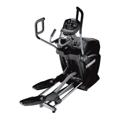
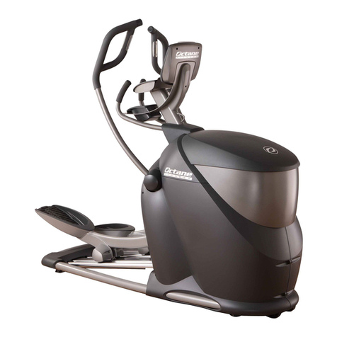
  9. Octane Fitness PRO3700 User manual

Octane Fitness PRO3700 User manual

PRO3700
2
3
PRO3700 ASSEMBLY INSTRUCTIONS
PERSONAL RECORD KEEPING
Tip: Record the serial numbers of your Octane Fitness® elliptical in the spaces below. This will make it easier
for you to obtain accurate and timely response should any service issues occur with your elliptical machine.
ATTENTION – All serial numbers begin with a letter.
Base Serial Number – located below front right track above the CSAFE and video inputs
__ __ __ __ __ __ __ __ __ __ __ __ __ __
Console Serial Number – located on the lower edge of the console
__ __ __ __ __ __ __ __ __ __ __ __ __ __
If you have any additional questions or need additional assistance in assembly, please contact your local
service provider or Octane Fitness Customer Service at 1.888.OCTANE4 ext. 1, You may also send an email to
[email protected], or visit us on the web at www.octanefitness.com.
WARNING: Machine contains moving parts. Use caution when assembling and operating this machine.
This product is intended for commercial use.
4
A
PRO3700 Contents
The Octane Fitness base box contains the following: Tools required:
A) 1 - Octane Fitness cross trainer base • Phillips screwdriver
B) 1 - Detached right pedal lever • 17mm wrench or adjustable wrench
C) 1 - Console mast • 17mm socket and ratchet
D) 1 - Top cover • 6mm hex key wrench
E) 1 - Access panel
F) 1 - Left moving handlebar
G) 1 - Right moving handlebar
H) 2 - Handlebar covers
I) 1 - Mast boot
J) 1 - Hardware pack (see opposite page)
K) 1 - Console Box (not pictured)
Box Contents
D
H
I
B
C
EFG
5
Hardware Pack (J) includes:
K) 8 - 6mm hex key chamfered bolt (for moving handlebars)
L) 2 - Phillips screws (for mounting access panel)
M) 2 - Phillips screws with washers (for mounting top cover)
N) 1 - Cable tie (for securing loose wires to mast)
KL M
N
The PRO3700 console box contains the following:
1) 1 - Console
2) 1 - Keypad
3) 2 - Console back arcs
4) 1 - Information packet
2
3
1
PRO3700
4
6
1. Attach right pedal lever
a. Remove bolt from 3-pivot link.
b. Attach right pedal lever (B) to 3-pivot link.
c. Tighten the bolt and nut securely using 17mm socket and
wrench.
2. Attach moving handlebars—Moving handlebars are
labeled left and right, be sure to install accordingly.
a. Align the bottom of the handlebar with the four holes in the
pivot shaft and attach with four 6mm hex key bolts (K)—
make sure these bolts are very tight; torque to 30 ft-
lbs., making sure not to crush the cable connectors.
b. Reaching inside from the front of the machine, carefully
connect the heart rate and button cables coming from the
base of the handlebar (F or G) to the corresponding cables
by the pivot shaft. (The connectors are different so that each
cable can only be connected to the correct corresponding
cable.) Gently tug both cables to ensure the connectors
are completely seated.
c. Repeat for the other side.
Pivot shaft
7
3. Install access panel
a. Loosen the screws on the left and right sides of the lower
shroud near the front of the unit. (These screws secure the
side of the shroud and the access panel to the frame.)
b. Slide the metal plate of the access panel (E) behind the
back shroud. Fit the tabs on each side of the access panel
into the slots between the side of the main shroud and the
frame, over the top of the screws.
b. Tighten the screws on each side, then secure the back of
the access panel with 2 Phillips screws (L).
Back
Screws
Tabs
Slot for
Tab
Screw to
loosen on
both sides
Tabs
Metal Plate
(under this edge)
4. Install console mast
a. Attach the console mast (C) by placing the keyhole slots in the
mast plate over the bolts and sliding the console mast toward
the pedals.
b. Tighten the four 6mm hex key bolts attaching console mast to
frame.
c. Connect all four (4) cable connectors coming from the
mast to the cable connectors on the base frame. Tug the
cables gently to ensure the connectors are completely
seated.
d. Use the cable tie (N) to secure any loose cable to the bottom
of the mast; cut off any excess cable tie.
Loosen screw
and fit tab
behind
8
5. Mount the keypad to the console mast
a. Remove the two screws securing the console back piece
to the mast plate.
b. Connect the green grounding wire from the heart rate
board to the tab mounted on the frame (next to the green
console grounding wire).
c. Connect the contact heart rate cables from the top of the
console mast tube (two gray cables joined at one white
connector) to the open connector on the heart rate board.
d. Route the cable from the other end of the heart rate board
down through the top of the mast tube and out of the hole
beneath the console plate.
e. Route the red and black fan wires with the white connector
down through the top of the mast tube and out of the hole
beneath the console plate.
f. Connect the ribbon cable from the top of the keypad (2) to
the black cable connector from the top of the mast tube.
g. Refer to the diagram below to see all the connections
and the action required. Tug each cable gently to
ensure each connector is completely seated.
h. Position the keypad (2) on the mast (C) and insert each of
the 4 shorter screws with washers through the mast holes
and into the keypad back. Tighten screws to secure.
Console/Keypad
(connect)
Heart Rate
(route)
Contact Heart Rate
(connect)
Fan Wire
(route)
Keypad Ground
(no action required)
Heart Rate
Ground
(connect)
CSAFE
(no action required)
Note: If you are using the optional LCD Mounting Arm, the PRO3700 Entertainment Kit, or the
PRO3700 900 MHz Audio Kit, skip step 6 of these instructions and instead follow the
instructions included with the LCD Mounting Arm. Once you have completed those
instructions, resume assembly of your PRO3700 with step 7 of these instructions.
9
6. Mount the console to the console mast
Note: Record the serial number of your console, located on the lower edge of the console, before
attaching the console to the console mast. (If you have installed the optional LCD Mounting Arm,
and mounted the console to the mast according to those instructions, skip to Step 7.)
a. Position the console (1) on the plate at the top of the mast
(C) and place the left back arc (3) behind it. Holding both
in place, insert 2 of the longer (18mm) Phillips screws
partially through the back arc (3) and the mast plate into
the console back. Repeat on the right side. Tighten all
screws to secure.
b. Attach the white 14-pin main connector to its connection
on the back of the console.
c. Attach the black keypad connector to its connection on the
back of the console.
d. Attach the metal connector on the green ground wire that
is connected to the back of the mast plate to its connection
on the back of the console.
e. Attach the white 3-pin heart rate connector to its connection
on the back of the console.
f. Attach the white 2-pin fan connector to its connection on
the back of the console.
g. Attach the white 5-pin CSAFE connector to its connection
on the back of the console.
h. Attach the white 6-pin handlebar keypads connector to its
connection on the back of the console.
i. Pedal the unit and verify that the console LEDs light and
that the Level and Program control buttons on the moving
handlebars are working. If any issues are detected, recheck
the connections, or contact Octane Fitness Customer
Service for assistance. Once you have verified these
functions, proceed with remaining steps.
j. Tug each cable gently to ensure each connector is
completely seated.
k. Make sure excess cable is pushed into the mast
tube.
l. Reposition the console back piece and reattach it using the
two screws provided.
Keypad
(black)
Console to Base
(white, 14-pin)
Fan
(white, 2-pin)
Heart Rate
(white, 3-pin)
Console Ground
(metal; green wire)
Handlebar Keypads
(white, 6-pin)
Software Update
(black)
CSAFE Audio
(white, 6-pin)
10
7. Adjust arms (optional)
Note: Before completing this step, ride the elliptical cross trainer for a few moments to get
a feel for the arm motion. If the reach of the arm motion feels right (as it will for most users),
proceed to step 8. If the reach is too long or too short, carefully follow these steps to shorten or
extend the reach by approximately 1.5 inches:
a. Locate the arm link that connects to the black bar (pivot)
inside the machine. The black bar has three holes in it with
the arm link attached through the center hole with a 13mm
nut.
b. While supporting the arm, remove the 13mm nut and
carefully ease the link from the center hole in the black bar.
To extend the reach of the arm, re-insert the link in the hole
closest to the front of your elliptical trainer. To shorten the
reach, re-insert the link in the hole closest to the user end of
the machine.
c. Replace the nut and tighten. This connection must be
very tight.
d. Repeat for the other arm.
Should you have any questions or concerns in making this
adjustment, please contact your local service provider or
contact Octane Fitness Customer Service at 1.888.OCTANE4,
ext. 1.
8. Place handlebar covers
a. Position the handlebar cover (H) at the base of the handlebar
(F or G).
b. Press cover onto handlebar until it snaps into place.
c. Repeat for other handlebar.
11
9. Adjust stride length (optional)
Note: The PRO3700 is initially set to the “Jogging” stride
length of 20.5”. To adjust to “Running” length (24”), follow
these steps:
a. Locate the 3-pivot link on the right side of the machine. It
is secured to the pivot arm by 3 bolts and a bracket. For
“Jogging” stride, the two forward bolts (away from the user)
are inserted in the center and upper holes in the 3-pivot link.
For “Running” stride, the 2 forward bolts must be inserted in
the center and lower holes.
b. Use 17mm wrenches to loosen bolt “A”, then remove the 2
forward bolts (“B” and “C”).
c. Lift up on the 3-pivot link and insert bolt “B” into the center
hole and bolt “C” into the lower hole in the 3-pivot link
(marked 24”); tighten.
d. Repeat steps 1-3 for the left side of the machine.
e. Grasp the plastic shroud “D” at the bottom of the rails and
pull up to remove it.
f. Use a 4mm hex wrench to remove bolts “E” and “F” securing
the center track cover “G” to the frame; slide the track cover
down.
f. Use a Phillips screwdriver to remove screws “H” and
“I” that secure the stride label badge to the track cover
“G”. Turn badge “J” from “Jogging” to “Running”, then
reposition the badge on the cover and secure with screws
“H” and “I”.
g. Slide the track cover up into position and secure it with the
bolts “E” and “F”.
h. Reposition the plastic shroud “D” at the bottom of the rails
and press it until it snaps into position.
h. Press and hold the Program and Level keys on the console.
Press the Up Arrow () key to set the stride length to
“Running”, then press Enter.
Note: The position of the bolts on both sides of the machine
and the console setting must match (Running or Jogging)
for the unit to work correctly.
A
B
C
I
J
G
H
12
11. Install mast boot
a. Place the rubber mast boot (I) around the mast (C), covering
the open ends of the stationary handlebars.
b. Tuck the ends of the mast boot (I) into the channels in the
access panel (E) just below the stationary handlebars.
10. Place top cover
a Align top cover (D) on top of main housing. Hold the back
edge (near the mast) in place and shift the front edge
forward until it settles into position.
b. While still holding the back edge in place, press firmly on
the bottom edge of the front of the cover until it snaps into
place. You will feel and hear it snap into place as
the plastic bracket on the inside of the front bottom
edge clips onto the steel tube at the front of the main
frame.
c. Secure the top cover to the access panel using 2 Phillips
screws with washers (M).
Steel tube
Press here
Hold here
Secure with
screws
12. (Optional) CSAFE Connection
a. If your facility is using CSAFE, connect the CSAFE
RJ-45 cable to the CSAFE port at the base of the machine.
Tug the cable gently to ensure the connector is
completely seated.
13
13. Adjust levelers
a. Adjust the levelers to make sure the product sits flat on the
floor. Begin by screwing all four levelers all the way into the
machine. If the floor is level, this should be sufficient. If there
is some uneveness in the floor, make minor adjustments to
the back levelers first to stabilize side-to-side motion, then
tighten the leveler nuts to the top of each back leveler to
lock.
b. Adjust the front levelers as necessary to eliminate any front-
to-back rocking. Tighten each leveler nut to the top of the
leveler to lock.
Note: If you move your PRO3700, you may need to adjust
the levelers to make sure your product is level with
the floor.
Caution: If the unit is not level, it may not function
properly.
Front Levelers
Rear Levelers
14. Set user preferences
a. Press and hold both the Up Arrow () and Down Arrow ()
keys for three seconds, or until you hear a double-beep.
Working with the owner of the unit, use the Up Arrow ()
or Down Arrow () key to step through the customizable
functions: Warm-up (On/Off), Clock Direction (Up/Down),
Max Workout Time, Unit Type (English/Metric), Beep (On/
Off), and Brightness. Use the Enter key to toggle through
the available options for each function, and press the Up
Arrow () or Down Arrow () key to select a setting and
move to the next function. To exit without changing any
values, press Pause Clear twice.
More detailed User Set-up information can be found in the
PRO3700 Operations Manual.
14
Moving the Product
It is safest to move the product to its installation location in its shipping carton. It may be easier to move the
product into your floor space after you remove it from the packaging, but be careful not to hit any walls or doors.
The PRO3700 features transport wheels on the front of the unit. Be careful when moving from one surface to
another, such as hardwood floor to carpet.
Note: If you need to pick up your elliptical there are hand placement slots under the front shroud. Please take
caution when lifting. The elliptical weighs 320 lbs. when fully assembled.
Tip: When using the front transport wheels, it is easier to pull the unit rather than push it.
NOTES
15
NOTES
FUEL YOUR LIFE™
Octane Fitness Octane Fitness International
US & Canada, Latin America, Asia & Asian Pacific Europe, Middle East, Africa
9200 Wyoming Avenue North Rivium Weestlaan 19
Suite 380 2909 LD, Capelle a/d Ijssel
Brooklyn Park, MN 55445 The Netherlands
Phone: 888.OCTANE4 (US and Canada) Phone: +31 10 2662412
763.757.2662 (Latin America, Asia and Asian Pacific) Fax: +31 10 2662444
Fax: 763.323.2064
©2010 Octane Fitness, LLC. All rights reserved. Octane Fitness, DedicatedLogic, Fuel Your Life, HeartLogic, Now-Zone, X-Mode, ArmBlaster, GluteKicker,
and SmartStride are registered trademarks of Octane Fitness. Any use of these trademarks, without the express written consent of Octane Fitness, is
forbidden.
102646-001 REV B
Are you passionate about your workout and the results?
Share your story with others on the Octane Fitness web site.
Go to: www.octanefitness.com/testimonials
Then click on “Share My Story” and
show the world how fueled you are.
www.octanefitness.com
www.youtube.com/user/octanefitness
www.facebook.com/octanefitness

Other manuals for PRO3700

5

Other Octane Fitness Fitness Equipment manuals
Octane Fitness Q37x User manual

Octane Fitness

Octane Fitness Q37x User manual

Octane Fitness Q47x User manual

Octane Fitness

Octane Fitness Q47x User manual

Octane Fitness XT4700 Quick setup guide

Octane Fitness

Octane Fitness XT4700 Quick setup guide

Octane Fitness Q37e User manual

Octane Fitness

Octane Fitness Q37e User manual

Octane Fitness Q47 Original instructions

Octane Fitness

Octane Fitness Q47 Original instructions

Octane Fitness Lateral X 8000 User manual

Octane Fitness

Octane Fitness Lateral X 8000 User manual

Octane Fitness AirRide User manual

Octane Fitness

Octane Fitness AirRide User manual

Octane Fitness CROSS CiRCUIT PRO ZR8000 Manual

Octane Fitness

Octane Fitness CROSS CiRCUIT PRO ZR8000 Manual

Octane Fitness PRO3700 User manual

Octane Fitness

Octane Fitness PRO3700 User manual

Octane Fitness xRide xR3c User manual

Octane Fitness

Octane Fitness xRide xR3c User manual

Octane Fitness LX8000 Assembly instructions

Octane Fitness

Octane Fitness LX8000 Assembly instructions

Octane Fitness PRO4500 User manual

Octane Fitness

Octane Fitness PRO4500 User manual

Octane Fitness LX 8000 Touch Setup guide

Octane Fitness

Octane Fitness LX 8000 Touch Setup guide

Octane Fitness LX8000 User manual

Octane Fitness

Octane Fitness LX8000 User manual

Octane Fitness xRide User manual

Octane Fitness

Octane Fitness xRide User manual

Octane Fitness Zero Runner 7 User manual

Octane Fitness

Octane Fitness Zero Runner 7 User manual

Octane Fitness Q35 User manual

Octane Fitness

Octane Fitness Q35 User manual

Octane Fitness LX8000 Setup guide

Octane Fitness

Octane Fitness LX8000 Setup guide
Octane Fitness CROSS CiRCUIT+ KIT Quick setup guide

Octane Fitness

Octane Fitness CROSS CiRCUIT+ KIT Quick setup guide

Octane Fitness 108581A User manual

Octane Fitness

Octane Fitness 108581A User manual

Octane Fitness BC1000 User manual

Octane Fitness

Octane Fitness BC1000 User manual
Octane Fitness xR6000 User manual

Octane Fitness

Octane Fitness xR6000 User manual

Popular Fitness Equipment manuals by other brands

Ideal World vibrapower slim 2 owner's manual

Ideal World

Ideal World vibrapower slim 2 owner's manual

Gaiam Wellbeing 05-62328 Setup, Workout Tips and Care & Safety Guide

Gaiam

Gaiam Wellbeing 05-62328 Setup, Workout Tips and Care & Safety Guide

TSS Monolift manual

TSS

TSS Monolift manual

SPIETH America 5175 Assembly and care instructions

SPIETH America

SPIETH America 5175 Assembly and care instructions

Ropeflex ORYX RX2500 Assembly & instruction manual

Ropeflex

Ropeflex ORYX RX2500 Assembly & instruction manual

ParaBody 887 user guide

ParaBody

ParaBody 887 user guide

BLUEFIN Fitness BLADE AQUA M-1 instruction manual

BLUEFIN Fitness

BLUEFIN Fitness BLADE AQUA M-1 instruction manual

EX N' Flex EF-300 Instructions for use

EX N' Flex

EX N' Flex EF-300 Instructions for use

Weslo Summit St80 owner's manual

Weslo

Weslo Summit St80 owner's manual

Nautilus ONE owner's manual

Nautilus

Nautilus ONE owner's manual

FOLLO FUTURA FOLLO STABILIS MANUPED manual

FOLLO FUTURA

FOLLO FUTURA FOLLO STABILIS MANUPED manual

Stamina 1205 PRECISION ROWER owner's manual

Stamina

Stamina 1205 PRECISION ROWER owner's manual

Making Life Easy 234702 manual

Making Life Easy

Making Life Easy 234702 manual

laerdal Nursing Anne Directions for use

laerdal

laerdal Nursing Anne Directions for use

Schuchmann todd Instructions for use

Schuchmann

Schuchmann todd Instructions for use

CYBEX VR2 Owner's and service manual

CYBEX

CYBEX VR2 Owner's and service manual

Nexo N200 manual

Nexo

Nexo N200 manual

SSG Leg Developer instructions

SSG

SSG Leg Developer instructions

manuals.online logo
manuals.online logoBrands
  • About & Mission
  • Contact us
  • Privacy Policy
  • Terms and Conditions

Copyright 2025 Manuals.Online. All Rights Reserved.