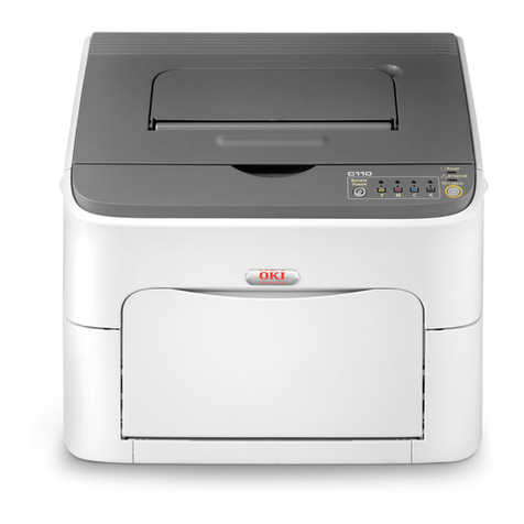
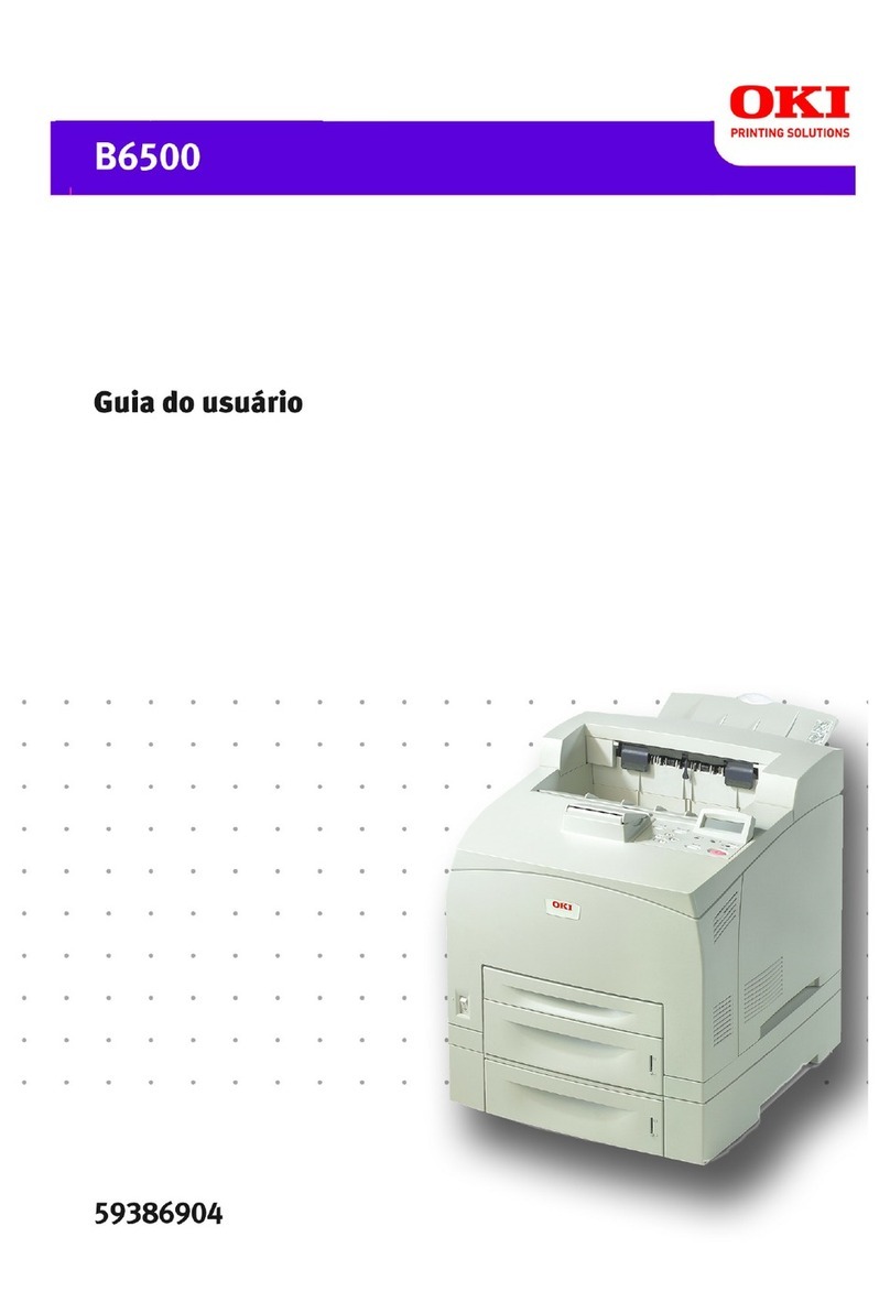
Oki B6200 Series User manual

Oki Data CONFIDENTIAL
B6200/B6300
Maintenance Manual
070111D

i
Cautions for operation
Contents of this document may be subjected to modification without previous notice.Oki Data
will assume no responsibilities for accidental or incidental damages
resulting from technical or editorial errors or omission in this manual, issue of this manual, execution of
description in this manual, or use of this manual.
This document is protected by copyright. It is not forgiven to photocopy or duplicate any part of this
document in any form without previous permission in writing from Oki Data.

ii
1. About this manual
This manual is a standard service manual of Oki Data containing information
required for maintenance of this laser printer (standard specifications).
The items described as “34PPM” are applied to the B6300 unit with 34ppm Print Engine Specifications.
The items describes as “24PPM” are applied to the B6200 unit with 24ppm Print Engine Specifications.
2. Marks giving caution
Maintenance operations requiring special cautions or additional information to descriptions of this
manual are presented as "Warning", "Caution", or "Note", according to their nature.
If instructions are not observed, serious injury may be caused.
If instructions are not observed, injuries of workers or physical damages to assets
(including this laser printer) may result.
Particularly important essentials for procedures, steps, rules, and others.
Reference Incidental information to descriptions.
3. Related documents
- Instruction manuals (standard manuals)
Describe operation and handling of this laser printer.
- Performance specifications
Describe in detail various specifications of this laser printer.
(In the event of discrepancy between this manual and the performance specifications, the
performance specifications shall take preference.)
-Video interface specifications
Detailed video interface specifications for this laser printer
-Spare parts list
Information on maintenance parts (spare parts) for this laser printer

iii
4. Safety
To prevent possible accidents during maintenance operation, you should observe the "Warning" and
"Caution" information in this manual.
Dangerous operations and operations out of range of this manual should be absolutely avoided.
Various processes not covered by this manual may be required in actual operation, which should be
performed carefully always giving attention to safety.
4.1 Power source
Keep the power supply off during maintenance operation to prevent electric shock, burns and other
damages. Keep the power plug disconnected during the maintenance operation.
If the power supply should be kept connected for measurement of voltage or other similar reasons,
sufficient care should be given to prevent electric shock, by following the procedures of this manual.
While the printer is ON, never touch live parts if not absolutely required .
Power is supplied to the power switch / inlet (LVPS ASSY) even while the printer is
off. Never touch its live components.
Do not touch live parts unless otherwise specified.
(34PPM) (24PPM)
JG0001AA
JG0101AA

iv
4.2 Driving units
When servicing gears or other driving units, be sure to turn them OFF and plug off. Drive them
manually when required.
Never touch the gears or other driving units while the printer is running.
(34PPM) (24PPM)
JG0002AA
JG0102AA

v
4.3 High-temperature units
When servicing high-temperature units (securing unit, etc.), be sure to turn them OFF to prevent burns,
injuries and other troubles, remove the power plug and start service processes after they have cooled
down enough.
Immediately after completion of operation, they are still hot. Start services after
more than 40 minutes.
(34PPM)
(24PPM)
JG0105AB
FUSERASSY
FUSERASSY
JG0005AB
Caution label
Caution label

vi
4.4 Laser beams
This laser printer has a switch (INTERLOCK S/W 5V) which stops providing power to the laser beam
output circuit physically in order to prevent from receiving laser beam of the laser beam output unit
(ROS ASSY). The switch turns to OFF when the top cover is opened.
Do not turn the switch ON by force except usual operations because there are possibilities that the
laser beam emits light when maintaining.
• If your eyes are exposed to laser beams, you may lose your eyesight.
• Never open the cover if warning label for laser beams is attached there.
• Before disassembling and reassembling this laser printer, be sure to turn it OFF.
• When servicing this laser printer while it is running, be sure to follow the
procedures specified in this manual.
• You should understand the features of the laser beams which are capable of
causing injury on the human body, not to extend the danger over the
workers as well as other people around the printer.
Laser beams have features as follows:
• Frequencies are smaller in width than other beams (sun and electric bulbs) and
phases are uniform so that high monochromatic and convergence performance
can be obtained and thin beams of light can reach places at a long distance.
• Due to the high convergence, beams are concentrated in high density and high
temperature, which is dangerous to human body.
Reference: Laser beams of this laser printer are invisible rays which you cannot see.

vii
(34PPM)
(24PPM)
ROSASSY
JG0104AB
Caution label
ROSASSY
JG0004AB
Caution label

viii
4.5 Warning/caution labels
Warning labels and caution labels are attached to this laser printer to prevent accidents. Check those
labels for their peeling or stain when servicing the printer.
4.5.1 Caution label for high-temperature units
It is labeled to the front side of fuser (FUSER ASSY) which become hot in order to prevent from
customers’ burn.
4.5.2 Caution label for laser beams
It is labeled to the top side of the output unit of laser beams (ROS ASSY) in order to prevent from that
workers for maintenance receive leaser beam.

ix
5. Installation
5.1 Power source
Do not plug too many leads into a single socket. Use a dedicated electric outlet and confirm that the
power is within the specification.
Connect the single power cord to an electric outlet which supplies power more
than the maximum power consumption of this laser printer.
5.2 Ground
Be sure to establish the ground of this laser printer.
Be sure to connect the ground of this laser printer with one of the followings:
- Grounding terminal of an electric outlet
- Copper or the like which is embedded 650 mm or deeper in the ground
- Grounding terminal for which the grounding work has been carried out
Be sure not to establish a ground with the followings:
- Gas pipe
- Ground for telephone
- Water pipe which is partially made from plastic
When establishing a ground, be sure not to use the 2pin - 3pin conversion plug.
5.3 Installation location
- Make sure there is enough space for operations of this laser printer.
- Install where the temperature and the humidity meet the following environment:
- During operation:5 to 35 degree C / 15 to 85 %RH (70%RH at 35 degree C, 85%RH at 32 degree C).
- no condensation
- Not in operation:-20 to 40 degree C / 5 to 85%RH (A place with no condensation)
- Install in a flat place with the angle of gradient of 5 degree or less.
- Install in a place with the illumination of 3000 Lux or less. (Avoid direct sunlight.)
- Avoid a place near a water system, a humidifier or fire, a dusty place, or a place which gets air blasting
of an air conditioning.
- Avoid where volatile or flammable gas is generated.
- Avoid an ill-ventilated place.
- Avoid an unstable and non-durable place.

x
5.4 Unpackings
5.4.1 Unpacking laser printer
The printer must be carried horizontally with two or more persons.
Extreme care must be taken to avoid personal injuries.
Unpack the carton, and confirm that the number of the later printer and the attachments, and their
appearances have no problem.
1) Laser Printer main unit
2) 150 Paper Cassette
3) 250/550 Paper Cassette
4) EP CARTRIDGE
5) Power Cord
6) Instruction Manual
5.4.2 Unpacking Option Face Up Tray
Unpack the carton, and confirm that the number of the Option Face Up Tray and the attachments, and
their appearances have no problem.
1) Option Face Up Tray main unit

xi
5.5 Installation Procedures
5.5.1 Installing laser printer
For details, refer to the Instruction Manual supplied with the main unit.
When holding up the laser printer, be sure to grasp the handles with both hands.
Grasping a part other than the handles may result in fall or damage of the laser printer.
When holding up the laser printer, bendyour knees thoroughly to prevent lower back
strain.
The protection sheets and the fixing materials, which are removed before the installation,
are re-used when the laser printer is moved to another place. Be sure to keep them.
1) Unpack the laser printer, and place it in an installation location after removing cushioning materials.
2) Confirm the attachments.
3) Peel off fixing tapes applied to the later printer.
4) Unpack the EP CARTRIDGE, then be sure to shake it seven to eight times holding both sides.
When removing the toner seal, draw it out straight and horizontally. After the
removal, be careful not to shake or give a shock to the EP CARTRIDGE.
5) Open the COVER OPEN, and install the EP CARTRIDGE.
6) Close the COVER OPEN.
7) Draw the paper tray, and press down the PLATE ASSY BTM to lock.
8) Place papers into the paper tray.
When placing papers into the paper tray, be careful for the followings:
- Align four corners of papers to place.
- Adjust the paper guide to the paper size.
- Do not place papers over the capacity or over the upper-limit line of the paper
tray.
9) Push the paper tray into the laser printer to install.
10) Connect the power cord.
11) Turn on the power switch of the laser printer.
12) Try some test printings with each paper-feed trays to confirm that there is no problem.
5.5.2 Installing Option Face Up Tray
For details, refer to the Instruction Manual supplied with the main unit.
Before the installation, turn off the power and plug off the power cord.
1) Unpack the Option Face Up Tray, remove cushioning materials, and confirm the attachments.
2) Insert the front edge of the Option Face Up Tray into the slot on the upper-rear of the laser printer to
install.
3) Connect the power cord.
4) Turn on the power switch of the laser printer.
5) Try some test printings to eject onto the Option Face Up Tray and confirm that there is no problem.

xii
6. Disassembly
6.1 Disassembly procedures
6.1.1 Disassembling laser printer and option units
For details, refer to the Instruction Manual or Chapter 3 Removal and Replacement Procedures.
Perform the disassembly in the reverse procedures of the installation.
When holding up the later printer, be sure to grasp the handles with both hands.
Grasping a part other than the handles results in fall or damage of the laser printer.
When holding up the later printer, bent your knees thoroughly to prevent the lower
back strain.
Be sure to remove the EP CARTRIDGE from the laser printer and put it into a
plastic bag to dismantle.
Be sure to re-use the protection sheets and fixing materials, which are removed at
the installation.
Confirm that no attachment is lacked.
Be sure to use the cushioning materials properly.

xiii
Chapter 1 Troubleshooting.............................................................................................1 - 1
Chapter 2 Operation of Diagnostic.................................................................................2 - 1
Chapter 3 Removal and Replacement Procedures........................................................3 - 1
Chapter 4 Plug/Jack(P/J) Connector Locations..............................................................4 - 1
Chapter 5 Parts List........................................................................................................5 - 1
Chapter 6 Principles of Operation ..................................................................................6 - 1
Chapter 7 Wiring Diagrams and Signal Information.......................................................7 - 1
Chapter 8 Printer Specifications.....................................................................................8 - 1

Chapter 1 Troubleshooting
Chapter 1 Troubleshooting CONTENTS
1. Progressing with the Troubleshooting.......................................................................1 - 1
1.1 Flow of Troubleshooting .............................................................. 1 - 1
1.2 Preparatory Requirements............................................................ 1 - 2
1.3 Cautions for Service Operations ....................................................... 1 - 3
1.4 Cautions for FIP Use................................................................. 1 - 4
2. Level 1 FIP.................................................................................................................1 - 6
2.1 Level 1 FIP ......................................................................... 1 - 6
2.2 Flow of Level 1 FIP .................................................................. 1 - 6
2.3 Error/Status Code List................................................................ 1 - 7
3. Level 2 FIP...............................................................................................................1 - 21
3.1 Level 2 FIP ........................................................................ 1 - 21
4. Error Code FIP.........................................................................................................1 - 22
4.1 Level 1 FIP ........................................................................ 1 - 22
FIP1.1 NVM Error...................................................................... 1 - 22
FIP1.2 ROS Error ...................................................................... 1 - 23
FIP1.3 FUSER Error.................................................................... 1 - 24
FIP1.4 FAN Error ...................................................................... 1 - 25
FIP1.5 MAIN MOTOR Error ............................................................. 1 - 26
FIP1.6 Cover Error ..................................................................... 1 - 27
FIP1.7 Paper Jam/Regi to Fuser ......................................................... 1 - 28
FIP1.8 Paper Jam/Exit.................................................................. 1 - 31
FIP1.9 Paper Jam/Tray to Regi .......................................................... 1 - 33
FIP1.10 Paper Jam/Misfeed.............................................................. 1 - 35
FIP1.11 EP CARTRIDGE................................................................ 1 - 38
FIP1.12 Paper Size Error ................................................................ 1 - 39
FIP1.13 No Tray/Tray 1, 2 ............................................................... 1 - 40
FIP1.14 No Paper/Tray 1, 2.............................................................. 1 - 41
FIP1.15 Low Paper in Tray/Tray 2 ........................................................ 1 - 42
FIP1.16 Drum Life ...................................................................... 1 - 43
FIP1.17 Fuser Life...................................................................... 1 - 44
FIP1.18 No Power ...................................................................... 1 - 45
FIP1.19 LCD/LED Display Error .......................................................... 1 - 48
FIP1.20 Inoperative Keypad.............................................................. 1 - 49
FIP1.21 Other Printer Error .............................................................. 1 - 50
FIP1.44 Face Up Tray Error.............................................................. 1 - 51
FIP1.45 Full Stack Error/500 Paper Exit ................................................... 1 - 52
4.2 Level 2 FIP ........................................................................ 1 - 53
FIP2.1 LVPS (PL12.1.5) ................................................................ 1 - 53
FIP2.2 MAIN MOTOR (PL11.1.2) ........................................................ 1 - 54
FIP2.3 ROS ASSY (PL8.1.1) ............................................................ 1 - 55
FIP2.4 FUSER ASSY (PL8.1.20)......................................................... 1 - 57
FIP2.5 SENSOR REGI (PL5.1.30)........................................................ 1 - 59
FIP2.6 SENSOR NO PAPER (PL5.1.38, PL6.1.38, PL7.1.38)................................ 1 - 61
FIP2.7 SENSOR LOW PAPER (PL6.1.4, PL7.1.4).......................................... 1 - 63
FIP2.8 SENSOR TONER (PL5.1.46) ..................................................... 1 - 64

Chapter 1 Troubleshooting
Chapter 1 Troubleshooting CONTENTS
FIP2.9 INTERLOCK S/W 24V (PL8.1.11).................................................. 1 - 65
FIP2.10 INTERLOCK S/W 5V (PL8.1.12), SWITCH I/L ASSY (PL1.1.11)....................... 1 - 66
FIP2.11 INTERLOCK S/W REAR (PL12.1.7) ............................................... 1 - 67
FIP2.12 SWITCH I/L ASSY (PL1.1.11) (Interlock S/W Front R) ............................... 1 - 68
FIP2.13 PWBA EXIT MOTOR (PL12.1.4) .................................................. 1 - 69
FIP2.14 MOTOR ASSY EXIT (PL9.1.11, PL10.1.15) ........................................ 1 - 70
FIP2.15 CLUTCH REGI (PL5.1.23) ....................................................... 1 - 71
FIP2.16 CLUTCH ASSY PH (PL5.1.21, PL6.1.21, PL7.1.20) ................................. 1 - 72
FIP2.17 GUIDE TRAY LEFT (PL7.1.7) .................................................... 1 - 73
FIP2.18 HVPS/MCU (PL12.1.19) ......................................................... 1 - 74
FIP2.19 Electrical Noise ................................................................. 1 - 75
FIP2.44 MOTOR ASSY EXIT (PL10.1.15) ................................................. 1 - 77
FIP2.45 SENSOR FACE UP OPEN (PL10.1.25)............................................ 1 - 78
FIP2.46 SENSOR FULL STACK (PL10.1.26)............................................... 1 - 79
5. Image Quality Trouble..............................................................................................1 - 80
5.1 Entry Chart for Image Quality Troubleshooting.......................................... 1 - 80
5.2 Image Quality FIP .................................................................. 1 - 82
FIP-1.P1 Faint print (Low contrast) ....................................................... 1 - 82
FIP-1.P2 Blank print (No print) ........................................................... 1 - 84
FIP-1.P3 Solid black.................................................................... 1 - 86
FIP-1.P4 Vertical blank lines (White stripes in paper transport direction)....................... 1 - 87
FIP-1.P5 Horizontal band cross out....................................................... 1 - 89
FIP-1.P6 Vertical stripes ................................................................ 1 - 91
FIP-1.P7 Horizontal stripes.............................................................. 1 - 92
FIP-1.P8 Partial lack.................................................................... 1 - 94
FIP-1.P9 Spots ........................................................................ 1 - 95
FIP-1.P10 Afterimage ................................................................... 1 - 96
FIP-1.P11 Background (Fog)............................................................. 1 - 98
FIP-1.P12 Skew........................................................................ 1 - 99
FIP-1.P13 Paper damage............................................................... 1 - 100
FIP-1.P14 No fix....................................................................... 1 - 102
6. Judgment of print consistency................................................................................1 - 103
Leading edge registration............................................................... 1 - 103
Side edge registration.................................................................. 1 - 104
Skew ................................................................................ 1 - 105
Perpendicularity ....................................................................... 1 - 106
Parallelism............................................................................ 1 - 107
7. Preventive maintenance.........................................................................................1 - 108

1 - 1
Chapter 1 Troubleshooting
This manual is based on the standard specifications of Oki Data
on the assumption that the printer controller is working properly.
When the printer controller controls operation directly or any OEM has its unique
specifications, the operation may be different from description in this manual.
Troubleshooting in this manual assumes use of Diag. tools (maintenance tools).
However, the troubleshooting allows for the case where the Diag tools are not
used. You can correct troubles according to these troubleshooting procedures
after understanding them well.
1. Progressing with the Troubleshooting
After making sure of actual condition of a trouble, proceed with the troubleshooting process efficiently
making use of the Fault Isolation Procedure (FIP), Operation of Dignostic (Chapter 2), Wiring Diagrams
(Chapter 7), and Principles of Operatin (Chapter 6).
1.1 Flow of Troubleshooting
Flow of the troubleshooting is as follows:
Prior check
Condition check
Start
Level 1 FIP
Trouble recovery check
Preventive
maintenance
End
Level 2 FIP
Operation of Diagnostic
Principles of Operation
Wiring Diagrams

1 - 2
Chapter 1 Troubleshooting
1.2 Preparatory Requirements
Be sure to check the following items before starting the troubleshooting procedures:
1) Voltage of the power supply is within the specifications (measure the voltage at the electric outlet).
2) Power cord is free from breakage, short-circuit, disconnected wire, or incorrect connection in the
power cord.
3) The laser printer is properly grounded.
4) The laser printer is not installed at a place subjected to too high temperature, too high humidity, too
low temperature, too low humidity or rapid change of temperature.
5) The laser printer is not installed close to water service, humidifier, heat generating unit, or fire, in
very dusty place, or a place exposed to air flow from the air conditioning system.
6) The laser printer is not installed in a place where volatile gas or inflammable gas is generated.
7) The laser printer is not installed under direct sunbeams.
8) The laser printer is installed in a well-ventilated place.
9) The laser printer is installed on a stout and stable plane.
10) Paper used meets specifications (standard paper is recommendable).
11) The laser printer is handled properly.
12) Parts which should be replaced periodically have been replaced when the specified number of
sheets have been printed.

1 - 3
Chapter 1 Troubleshooting
1.3 Cautions for Service Operations
1) Be sure to remove the power cord except when it is specifically required.
If the printer is kept ON, never touch the conductive parts while it is not specifically
required.
The power switch and inlet of LVPS is live even while the power supply is cut off.
Never touch the live parts.
2) When checking some parts with covers removed and with the interlock and safety and power
switches ON, remove the connector (P/J140) on the ROS ASSY except when it is specifically
required.When checking some parts with covers removed and with the interlock and safety
and power switches ON, laser beams may be irradiated from the ROS ASSY. Since
it is dangerous, be sure to remove the connector (P/J140) while it is not required.
3) When checking some parts with the left cover removed and power ON, be sure to remove the
connector (P/J31) on the HVPS/MCU while it is not required.
When checking some parts with the left cover removed and power ON, high voltage
may be applied by the HVPS. Be sure to remove the connector (P/J31) on the HVPS/
MCU.
When connecting the connector (P/J31) on the HVPS/MCU according to the
instructions of the FIP, never touch the HVPS and parts of high voltage.
4) When using Diag. tools or other tools of high voltage, be sure to keep them covered except when
otherwise specified.
When using Diag.Tool or other tools of high voltage, never touch parts of high
voltage.
When using Diag. Tool or other tools of high voltage, be sure to follow the
procedure of this manual.
5) When operating the driving units using the Diag or other tools, be sure to keep them covered
unless otherwise specified.
When operating the driving units using the Diag or other tools, never touch the
driving units. When operating the driving units using Diag or other tools, be sure to
follow the procedures in this manual.
6) When touching hot parts, be careful not to get burnt.
7) Workers should wear a wrist strap or the like to remove static electricity from their body, grounding
their body while working.
To avoid injury, be sure to remove the wrist strap before working on or near high-
voltage power sources, components, or devices.

1 - 4
Chapter 1 Troubleshooting
1.4 Cautions for FIP Use
1) It is assumed in the FIP that the printer controller (PWBA ESS) is normally functioning. If any
trouble cannot be corrected by troubleshooting, replace the printer controller with a normal one and
check for proper operation again.
If the trouble is not still corrected, replace the major parts and then related parts in succession and
confirm according to the procedure of the “Check”.
2) When troubleshooting according to the FIP, normal HVPS/MCU, LVPS, FUSER ASSY, BTR ASSY
and so no may be necessary for isolation of failed parts. Prepare them in advance.
3) In the initial check according to the FIP, check only items which can be simply checked.
4) In the initial check according to the FIP, check the constitutive parts of the major check parts and
related parts, as well as major check parts.
5) When working with the printer, be sure to remove the power cord except when required
specifically. Never touch live parts if not required, while the power cord is connected.
6) Connector condition is denoted as follows:
[P/J12] →Connector (P/J12) is connected.
[P12] →Plug side with the connector (P/J12) removed (except when attached directly to the
board).
[J12] →Jack side with the connector (P/J12) removed (except when attached directly to the
board).
7) [P/J1-2PIN <=> P/J3-4PIN] in the FIP means measurement with the plus side of the measuring
instrument connected to [2PIN] of [P/J1] and the minus side to [4PIN] of [P/J3].
8) [P/J1<=> P/J2] in the FIP means measurement for all terminals corresponding between [P/J1] and
[P/J2] referring to “Wiring Diagrams”.
9) In [P/J1-2PIN <=> P/J3-4PIN] in the FIP where voltage is measured, [P/J3-4PIN] on the rear minus
side is always at the AG (analog ground), SG (signal ground), or RTN (return).
Therefore, after checking of proper continuty between AGs, SGs, or RTNs respectively, the rear
minus side can be connected to the PIN of AG, SG or RTN instead of [P/J3-4PIN].
However, care should be taken not to mistake since [AG], [SG], and [RTN] are not on the same
level.
10) Measure the voltage of small connectors with the special tool. Handle the tool with care, as the
leading edge of the tool is pointed.
11) When measuring the voltage, set the EP CARTRIDGE, BRT ASSY and paper tray, close the
COVER TOP ASSY, FUSER ASSY, and COVER REAR and power ON if not required specifically.
12) Numerical values in the FIP are only for standard. If numerical values are approximate, they should
be considered permissible.
Other manuals for B6200 Series
6
This manual suits for next models
1
Table of contents
Other Oki Printer manuals