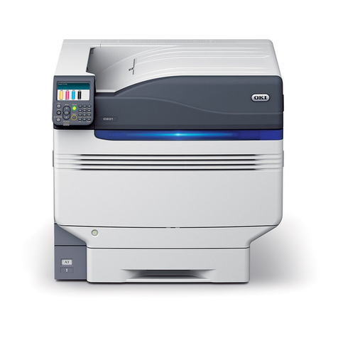
Oki C910 User manual

C910 / C930
Troubleshooting Guide
Distributed at the Oki Data A3/C9 Service Training Classes.
Rev. 3.20
Troubleshooting Guide Page 1

This Page Intentionally Left Blank
Troubleshooting Guide Page 2

Oki Data CONFIDENTIAL
5. Adjustment
The printer is adjusted by key operation on the Maintenance Utility and the Operator Panel.
Select the menu according to the items to adjust and the purpose of adjustment.
5.0 System Maintenance Menu
This menu is launched by turning on the power source while keeping the [Menu+]+[Menu-]+[Help]
switches pressed.
The menu display is only available in English regardless of destination.
Note
• This menu can be modified according to the destination, etc. Therefore, it is not
open (closed) to the end user.
• C910 needs password to enter the System Maintenance Menu. Default is "000000".
Caution
Do not reset the OKIUSER Setting of the C930 Series.
Resetting OKIUSER resets settings made in it, including its model name and server
name. When the OKIUSER menu has been entered on it, press the Return button
to exit from the menu.
Category Item Value DF Old Menu Function Vailid Save
System
Maintenance
OKI USER ODA
OEL
APS
JP1
JPOEM1
OEMA
OEML
* "SYSTEM
MAINTENANCE
MENU" -
"OKIUSER" -
"OKIUSER"
Set the destination.
JPOEM1: Japan OEM
OEMA : A4 Default Overseas OEM
OEML :
Letter Default Overseas OEM
Automatically reboot after escaping
from the menu.
The default value for non-PS
models is JP1.
RB -
Maintenance
Menu
NEXT This displays the menu to initialize
the harddisk and Flash ROM.
Maintenance
Print Menu
Enable
Disable *
This switches whether to Show/
Hide the "Print Information" – "ID
Check Pattern" and "Engine Status"
of the Function Menu. If this item
is disabled, the "Print Information"
– "ID Check Pattern" and "Engine
Status" of the Function Menu is
never displayed.
The printer is restarted after the
settings are modified and escaping
from the menu.
ET -
Print Page
Count
Enable
Disable *
"SYSTEM
MAINTENANCE
MENU" - "PAGE
CNT PRINT" -
"PAGE CNT PRINT"
This sets whether to Show/Hide
the display of the "Functions"-
"Configuration" - "Print Page
Count"-"Total Page".
ET -
Personality NEXT This displays the menu to edit the
default PDL language supported
according to destination.
Change
Password
NEXT
Diagnostic
Mode
"SYSTEM
MAINTENANCE
MENU"-
"DIAGNOSTIC
MODE XX.XX"
This goes to the engine’s self-
diagnosis mode.
ET -
Table 5-0. Maintenance Menu Display Table (1/2)
Troubleshooting Guide Page 3

Table 5-0. Maintenance Menu Display Table (2/2)
During the Engine Self-Diagnosis Mode, switch operations and the LCD display is instructed by the
engine firmware, therefore, it will vary from the specifications of the controller firmware operations.
Note that the Engine Self-Diagnosis Mode can also be executed in the state with the controller PCD
removed.
For details, accordingly refer to the Engine Specifications Manual.
Value
Execute
NEXT
Execute
Execute
Enable
Disable
Enable
Disable
Enable
Disable
Execute
Execute
Item
Format HDD
Format
Flash ROM
Reset
EEPROM
Reset
Parameter
IBM PPR
III XL
EPSON
FX
HP-GL/2
Slot 0
Slot 1
Category
Maintenance
Menu
Personality
Format
Flash ROM
Function
Initialize the HDD. When executed it
will escape from the menu and start
initializing the HDD.
[Display Condition]
¥Mount HDD ( Boot Menu - Storage
Setup - Enable Initialization
Enable, Boot Menu - Storage
Setup - Enable HDD Yes)
This displays the menu to initialize
the Flash ROM.
This resets the EEPROM details to
the factory preset (factory default)
value. It automatically reboots after
the settings are made and applied.
* Some special items are not
initialized.
This resets the EEPROM details to
the factory preset (factory default)
value. At that time, the OEM related
settings that are not initialized with
Reset EEPROM will also be
initialized.
It automatically reboots after the
settings are made and applied.
* Some of the PU, network, etc.
cannot be initialized.
Changes the default PDL language
supported according to the destination.
The PDL language disabled from
this menu will no longer be displayed
on the Print Setup — Personality
of the Function menu. When
receiving print data in the disabled
PDL language, display INVALID
DATA and dispose the incoming
data. (HP-GL/2 is currently under
development and there are no plans
scheduled for application for the
product). PDF requires Adobe
Postscript, therefore, it is not
possible to turn PDF ON/OFF by
itself (if Adobe Postscript is
DISABLED, the PDF Function will
also be DISABLED).
It is not possible to DISABLE Adobe
Postscript and PDF with PX711/713.
(It shall be usually used in the
ENABLE state. Though DISABLE is
set the incoming data will still be
processed. It has been incorporated
for future extension purposes.)
Initialize the Flash ROM.
Escape the menu to execute, then
start formatting the Flash device
mounted on the resident (onboard).
Initialize the Flash ROM.
Escape the menu to execute, then start
formatting the Flash device mounted
on the wireless LAN (Optional).
Old Menu
SYSTEM
MAINENANCE
MENU —
MAINTENANCE
MENU — HDD
INITIALIZE
SYSTEM
MAINENANCE
MENU -
MAINTENANCE
MENU — FLASH
INITIALIZE
SYSTEM
MAINENANCE
MENU -
MAINTENANCE
MENU — MENU
RESET
SYSTEM
MAINENANCE
MENU -
PERONALITY —
IBM PPR III XL
SYSTEM
MAINENANCE
MENU -
PERONSALITY
— EPSON fx
SYSTEM
MAINENANCE
MENU -
PERSONALITY
— hp-gl/2
DF
-
-
-
-
*E
*J
*E
*J
*JE
-
-
Valid
ET
RB
RB
RB
ET
ET
Save
-
-
-
-
-
-
-
Troubleshooting Guide Page 4

YM+Y M C K Y
M+Y
M
C
K
5.0.1 ID Check Pattern Print (“TEST PRINT MENU” Item)
This pattern can be used to investigate the cause (plain identification of problem or check cycle of
problem) resulting from the ID or LED head. CMYK are each composed of a 20% duty pattern. (printing
2 sheets)
Test Pattern Print Procedure : (Switch pressing order)
* HDD = NO : “0” →“0” →“3” →“3”
* HDD = YES : “0” →“0” →“0” →“3” →“3”
• Vertical Black/White Lines (Vertical Black/White Lines)
• Vertical Black/White Band (Vertical Black/White Band)
• Horizontal Black/White Lines (Horitzontal Black/White Lines)
• Horizontal Black/White Band (Horitzontal Black/White Band)
Print pattern (Print Pattern):
Page.1 Page.2
5.1 Maintenance Menu and Its Function
5.1.1 Maintenance Menu
There is a Maintenance Menu Category in a regular menu category.
The following items can be set from this menu.
Troubleshooting Guide Page 5

Maintenance Menu
Category
MAINTENANCE MENU
Item (1st Line)
EEPROM
Reset
SAVE MENU Setting
RESTORE MENU
POWER SAVE
Plain Paper Black Set-
ting
Plain Paper Color Set-
ting
Transparency Black
Setting
Transparency Color
Setting
DF
*
*
*
*
*
*
*
*
Value (2nd Line)
EXECUTE
EXECUTE
EXECUTE
ENABLE
DISABLE
0
+1
+2
-2
-1
0
+1
+2
-2
-1
0
+1
+2
-2
-1
0
+1
+2
-2
-1
Function
Reset the EEPROM of the CU.
Save the current menu settings.
An ARE YOU SURE? YES/NO
selection message appears.
Modify the setting to the menu set-
ting saved. (Display only when
there is a menu setting saved)
Saved on the Flash
(surface-mounted) of the
CU. Saved on the HDD if
there is a HDD.
This sets the ENABLE/DISABLE of
the power save mode.
When the power save mode is en-
abled, the time it takes to activate
the power save mode can be modi-
fied by the Power Save Delay Time
Item in the System Config Menu.
Plain Paper/Black Print: This fine-
tunes any uneven printing or dust in
the printouts. Decrement this set-
ting if there is any scattering in high
density printing or if there is snow-
like patterns in the printout. Incre-
ment this setting if the printout ap-
pears whiting out.
Plain Paper/COLOR Print: This is
used to fine-tune any uneven print-
ing or dust in the printouts. Decre-
ment this setting if there is any
scattering in high density printing or
if there is snow-like patterns in the
printout. Increment this setting if the
printout appears whiting out.
Transparency/BLACK Print: This is
used to fine-tune any uneven print-
ing or dust in the printouts Decre-
ment this setting if there is any
scattering in high density printing or
if there is snow-like patterns in the
printout. Increment this setting if the
printout appears whiting out.
Transparency/COLOR Print: This is
used to fine-tune any uneven print-
ing or dust in the printouts Decre-
ment this setting if there is any
scattering in high density printing or
if there is snow-like patterns in the
printout. Increment this setting if the
printout appears whiting out.
Note
Troubleshooting Guide Page 6

5.1.2 Engine Maintenance Mode
Engine maintenance mode tests the basic operation of the print engine components.
5.1.2.1 Operation Panel
Instructions on self-diagnosis operations is based on the following Operation Panel layout, as a
prerequisite.
Troubleshooting Guide Page 7

5.1.2.2 Regular Self-Diagnosis Mode (Level 1)
The Regular Self-Diagnosis Mode menu is as follows.
• Switch Scan Test
• Motor and Clutch Test
• Execute Test Pattern
• Initialize NVM
• Consumable Counter Display
• Consumable Continual Counter Display
5.1.2.2.1 How to Enter Self-Diagnosis Mode (Level 1)
1. Press the [MENU+], [MENU-] and [HELP] keys at the same time when turning ON the
power to go to the System Maintenance Mode.
2. Press the [MENU+] and [MENU-] key until the “DIAGNOSTIC MODE” is displayed.
3. “Diagnostic Mode XX.XX.XX” appears on the LCD panel. The XX.XX.XX stands for the
version of the ROM. At the bottom right the setting of the “Factory Working Mode” is
displayed. This is usually “S-MODE”.
4. Press the [MENU+] or [MENU-] key to go to each self-diagnostic step. (The menu item
rotates by pressing the [MENU+] or [MENU-] keys)
5.1.2.2.2 Escape from Self-Diagnosis Mode
1. Turn OFF the power then re-turn it ON after 10 seconds.
DIAGNOSTIC MODE
XX.XX.XX S-MODE
Troubleshooting Guide Page 8

5.1.2.3 Switch Scan Test
This self-diagnosis is sued to check the input sensor and switch.
SWITCH SCAN
1. Keep the [MENU+] and [MENU-] keys pressed until [SWITCH SCAN] appears at the top
of the display and operations goes into the regular diagnosis mode. (The [MENU+] key
= Increment Test Item / the [MENU-] key = Decrement Test Item.)
2. The following message appears by pressing [ENTER]
SWITCH SCAN
PAPER ROUTE: PU
3. Keep the [MENU+] and [MENU-] keys pressed until the item that applies to the unit to
test from Table 5-1-1 appears, at the top of the display.
Press the [
MENU+] and [MENU-] keys
. The [MENU+] key = Increment Test Item /
the
[MENU-] key
= Decrement Test Item.
PAPER ROUTE: PU
1=H 2=L 3=H 4=L
4. The test is started by pressing the [ENTER] key. The top of the display starts blinking and
the applicable unit number (1-4) and the current state appears.
Operate each unit (Figure 5-1). Display the operations on each respective applicable LCD
area. (The display varies according to each sensor. For details refer to Table 5-1-1.)
5. Press the [CANCEL] or [BACK] key to return to state 2.
6. Accordingly repeat Steps 2 to 4.
7. To end the test press the [BACK] key. (Return to state 1)
Troubleshooting Guide Page 9

No5-1 Stacker Full FD SNS
No32-1
No32-1
Dup IN1 SNS
Dup IN1 SNS
15-1 MPT PE SNS
15-1 MPT PE SNS
15-2 MPT PE SNS2
15-2 MPT PE SNS2
16-1 MPT Hopping SNS
8-1 Hum SNS, 8-2 Temp SNS
6-4 Media Weight SNS
1-3 WR SNS
1-3 WR SNS
1-2 IN2 SNS
1-2 IN2 SNS
16-2 MPT Home SNS
16-2 MPT Home SNS
1-1 IN1 SNS
1-1 IN1 SNS
18-1 1stHopping SNS
18-1 1stHopping SNS
32-3 Dup F SNS
32-3 Dup F SNS
6-1,2 Alignment L,R SNS
33-1 Dup IN2 SNS
33-1 Dup IN2 SNS
No19-1~No19-4
No19-1~No19-4
1stPaper Size SW
1stPaper Size SW
No5-4 JobOffset HP SNS
No22-1~No22-4
No22-1~No22-4
1stPaper Size SW
1stPaper Size SW
21-1 2ndHopping SNS
21-1 2ndHopping SNS
20-2 2ndPaper Near END SNS
20-1 2ndPaper END SNS
21-2 2ndLifter SNS
21-2 2ndLifter SNS
21-3 2ndFeed SNS
21-3 2ndFeed SNS
20-3 Cover Open 2nd SW
17-2 1stPaper Near END SNS
17-1 1stPaper END SNS
18-2 1stLifter SNS
18-2 1stLifter SNS
18-3 1stFeed SNS
18-3 1stFeed SNS
17-3 Cover Open 1st SW
13-2 Disposal toner box
12-4 Waste Toner Hole IC
12-3 Belt Hole IC
12-3 Belt Hole IC
4-1 Cover Upper
4-1 Cover Upper
15-3 Cover MPT
15-3 Cover MPT
No10-1 TAG (K)
No10-1 TAG (K)
No10-2 TAG (Y)
No10-2 TAG (Y)
No10-3 TAG (M)
No10-3 TAG (M)
No10-4 TAG (C)
No10-4 TAG (C)
No5-2
No5-2
Stacker Full FU SNS
Stacker Full FU SNS
No5-3
No5-3
Job off Paper Back End SNS
No4-3 Cover Face Up
No4-3 Cover Face Up
No4-2 Cover Left Upper
1-4 Exit SNS
1-4 Exit SNS
12-2
12-2
Paper Slack SNS
Paper Slack SNS
12-1 Fuser Release SNS
32-2
32-2
Dup R SNS
Dup R SNS
Figure 5-1 Location of Switching Sensor
Troubleshooting Guide Page 10

H:OFF
L:ON
H:ON
L:OFF
H:ON
L:OFF
Frequency
AD Value:
***H
H:Up
L:Down
UID:****H
Port Level
H, L
H:ON
L:OFF
Port Level
H, L
H:Open
L:Close
Port Level
H, L
Port Level
H, L
Port Level
H, L
Port Level
H, L
Port Level
H, L
Table 5-1-1 Switch Scan Details
No.
1
Detail
Top of the
Display Display
2
Detail Display
3
Detail Display
4
Detail Display
PAPER ROUTE
: PU
PAPER ROUTE
: SUB
TONER SENS
COVER
UP_LU_FU
STKF_FD_FU
JOBOFFHOME
REG L/R_
DENS_WEIGHT
HEATER
THERMISTER
HUM_TEMP_OHP
ID UP/DOWN
RFID COLOR
DRUM PHASE
SNS KYMC
F-RLS SLK BLT
DT-DCT
DISTNR
FULL_BOX_BOXSP
TNR SPLY SNS
KY_MC
MPT PE_
HOP_CVO_HOME
TRAY1 PE_
PNE_CVO
TRAY1
HOP_LIFT
TRAY1 CASETTE
SIZE
TRAY2
PE_PNE_CVO
TRAY2
HOP_LIFT_FEED
TRAY2 CASETTE
SIZE
TRAY3
PE_PNE_CVO
TRAY3
HOP_LIFT_FEED
TRAY3 CASETTE
SIZE
TRAY4
PE_PNE_CVO
TRAY4
HOP_LIFT_FEED
TRAY4 CASETTE
SIZE
TRAY5
PE_PNE_CVO
TRAY5
HOP_LIFT_FEED
TRAY5 CASETTE
SIZE
DUP INS_
REAR_FRONT
1
2
3
4
5
6
7
8
9
10
11
12
13
14
15
16
17
18
19
20
21
22
23
24
25
26
27
28
29
30
31
IN1 Sns
IN1 Sns
Toner-K Sns
Cover-Upper
Stacker Full Sns
(Face down)
Aligment-Left-
Sns
Upper-Center-
Thermister
Hum Sns
TAG-K presence
K-Drum Phase
Sns
Fuser Release
Sns
Disposal toner
full
K-Toner Supply
Sns
MPT-Paper-End
Sns
1st-Paper-End
Sns
1st-Hopping
Sns
1st-Paper Size-
1 Sw
2nd-Paper-End
Sns
2nd-Hopping
Sns
2nd-Paper Size-
1 Sw
3rd-Paper-End
Sns
3rd-Hopping
Sns
3rd-Paper Size-
1 Sw
4th-Paper-End
Sns
4th-Hopping
Sns
4th-Paper Size-
1 Sw
5th-Paper-End
Sns
5th-Hopping
Sns
5th-Pape rSize-
1 Sw
Dup-In Sns
H:OFF
L:ON
H:OFF
L:ON
H:ON
L:OFF
H:Open
L:Close
H:Full
L:Empty
AD Value:
***H
AD Value:
***H
AD Value:
***H
UID:****H
Port Level
H, L
H:ON
L:OFF
H:ON
L:OFF
Port Level
H, L
Port Level
H, L
Port Level
H, L
Port Level
H, L
Port Level
H, L
Port Level
H, L
Port Level
H, L
Port Level
H, L
Port Level
H, L
Port Level
H, L
Port Level
H, L
Port Level
H, L
Port Level
H, L
Port Level
H, L
Port Level
H, L
Port Level
H, L
Port Level
H, L
Port Level
H, L
IN2 Sns
IN2 Sns
Toner-Y Sns
Cover-Left
Upper
Stacker Full Sns
(Face up)
Aligment-Right-
Sns
Lower-Center-
Thermister
Temperture-Sns
TAG-Y presence
Y-Drum Phase
Sns
Paper Slack
Sns
Disposal toner
box
Y-Toner Supply
Sns
MPT-Hopping
Sns
1st-Paper-Near-
End Sns
1st-Lifter Sns
1st-Paper Size-
2 Sw
2nd-Paper-
Near-End Sns
2nd-Lifter Sns
2nd-Paper Size-
2 Sw
3rd-Paper-Near-
End Sns
3rd-Lifter Sns
3rd-Paper Size-
2 Sw
4th-Paper-Near-
End Sns
4th-Lifter Sns
4th-Paper Size-
2 Sw
5th-Paper-Near-
End Sns
5th-Lifter Sns
5th-Paper Size-
2 Sw
Dup-Rear Sns
H:OFF
L:ON
H:OFF
L:ON
H:ON
L:OFF
H:Open
L:Close
H:Full
L:Empty
AD Value:
***H
AD Value:
***H
AD Value:
***H
UID:****H
Port Level
H, L
H:ON
L:OFF
H:Not
installed
L:Installed
Port Level
H, L
H:ON
L:OFF
Port Level
H, L
Port Level
H, L
Port Level
H, L
Port Level
H, L
Port Level
H, L
Port Level
H, L
Port Level
H, L
Port Level
H, L
Port Level
H, L
Port Level
H, L
Port Level
H, L
Port Level
H, L
Port Level
H, L
Port Level
H, L
Port Level
H, L
Port Level
H, L
WR Sns
WR Sns
Toner-M Sns
Cover-Face Up
Job Offset
Paper-End Sns
Upper-Side-
Thermister
OHP Sns
TAG-M presence
M-Drum Phase
Sns
Belt Hole IC
M-Toner Supply
Sns
Cover-MPT
Cover-1st
1st-Feed Sns
1st-Paper Size-
3 Sw
Cover-Open-
2nd Sw
2nd-Feed Sns
2nd-Paper Size-
3 Sw
Cover-Open-3rd
Sw
3rd-Feed Sns
3rd-Paper Size-
3 Sw
Cover-Open-4th
Sw
4th-Feed Sns
4th-Paper Size-
3 Sw
Cover-Open-5th
Sw
5th-Feed Sns
5th-Paper Size-
3 Sw
Dup-Front Sns
H:OFF
L:ON
H:OFF
L:ON
H:ON
L:OFF
H:Open
L:Close
H:ON
L:OFF
AD Value:
***H
AD Value:
***H
UID:****H
Port Level
H, L
H:ON
L:OFF
Port Level
H, L
H:Open
L:Close
H:Open
L:Close
Port Level
H, L
Port Level
H, L
Port Level
H, L
Port Level
H, L
Port Level
H, L
Port Level
H, L
Port Level
H, L
Port Level
H, L
Port Level
H, L
Port Level
H, L
Port Level
H, L
Port Level
H, L
Port Level
H, L
Port Level
H, L
Port Level
H, L
Exit Sns
Toner-C Sns
JobOffset Home
Position Sns
Media Weigt-
Sns
Detect-ambient
temperature-
Thermister
ID UpDown Sns
TAG-C presence
C-Drum Phase
Sns
Waste Toner
Hole IC
C-Toner Supply
Sns
MPT Home
Position Sns
1st-Paper Size-
4 Sw
2nd-Paper Size-
4 Sw
3rd-Paper Size-
4 Sw
4th-Paper Size-
4 Sw
5th-Pape Size-4
Sw
Troubleshooting Guide Page 11

H:OPEN
L:CLOSE
H:Paper
present
L:Paper
absent
H:Home
position
L:Except in
the home
position
H:Home
position
L:Except in
the home
position
H:Not to
drive
L:Drive
H/L:Clock
H:Paper
detect position
L:Except in
the paper
detect position
H:Open
L:Close
Table 5-1-2 Paper Size Detection, Various Paper Types and Bits- corrected 2-11
No. 1
Detail
Top of the
Display Display
2
Detail Display
3
Detail Display
4
Detail Display
32
33
34
35
36
37
38
39
40
41
42
43
DUP
STACK_COVER
FIN S01_S02_
S03_S04
FIN S05_S06_
S07_S08
FIN S09_S10_
S11_S12
FIN S13_S14_
S15_S16
FIN S17_S18_
S19_S20
FIN S21_S22_
S23_S24
FIN S25_S26_
S27_S28
FIN S29_S30_
S31_S32
INV IN_OUT_
EXIT_COV
INV REMAIN_
JOINT
HALL BELT_
DT-BOX_DCT
Dup-Stack Sns
Uper Cover Sns
[PI23]
Bookbinding
position
Sns[PI10]
Bookbinding
tray paper Sns
[PI13]
Rear matching
home position
Sns [PI5]
Staple / fold
motor clock
[PI14]
Staple home
position
Sns[PI19]
Lower stack tray
Sns [PI16]
Stack tray paper
Sns [PI8]
Entrance Sns
[FP1]
Lower Sns[FP3]
Belt Hole IC
Port Level
H, L
H:OPEN
L:CLOSE
H:Paper
present
L:Paper
absent
H:Paper
present
L:Paper
absent
H:Home
position
L:Except in
the home
position
H/L:Clock
H:Home
position
L:Except in
the home
position
H:Lower
position
L:Except in
the lower
position
H:Paper
present
L:Paper
absent
H:ON
L:OFF
H:ON
L:OFF
H:ON
L:OFF
Dup-Cover
Open Sns
Front door Sns
[PI22]
Processing tray
Sns [PI6]
Bookbinding
home position
Sns [PI11]
Belt home
position outlet
Sns [PI7]
Self prime Sns
[PI21]
Stapler slide
home position
Sns [PI18]
Upper stack tray
Sns [PI15]
Punch connect
signal
Outlet Sns
[FP2]
Inverter
connected Sns
[FP4]
Waste Toner
Box Hole IC
Port Level
H, L
H:OPEN
L:CLOSE
H:Paper
present
L:Paper
absent
H:Home
position
L:Except in
the home
position
H:Home
position
L:Except in
the home
position
H:Start
staple
detection
L:Staple
absent
H:Home
position
L:Except in
the home
position
H:Upper
position
L:Except in
the upper
position
Hconnected
Lunconnected
H:ON
L:OFF
H:ON
L:OFF
H:ON
L:OFF
Front door SW
[MS2]
Entrance Sns
[PI1]
Bookbinding
roller home
position Sns
[PI12]
Feed roller
home position
Sns[PI3]
Staple Sns
[PI20]
Stapler connect
signal
Interlevel stack
tray Sns [PI24]
PU→Inverter
Exit Sns Signal
PU→Inverter
CNT2 Signal
Waste Toner
Hole IC
H:OPEN
L:CLOSE
H:Paper
present
L:Paper
absent
H:Home
position
L:Except in
the home
position
H:Home
position
L:Except in
the home
position
H:Staple
absent
L:Staple
present
Hconnected
Lunconnected
H:Interlevel
detection
L:Interlevel
undetection
H:ON
L:OFF
H:ON
L:OFF
H:ON
L:OFF
Joint SW [MS1]
Punch timing
Sns
Front matching
home position
Sns [PI4]
Paddle home
position [PI2]
Stapler safty
SW [MS3]
Stack tray lift
motor
clock[PI17]
Paper stack tray
Sns [PI9]
Cover open SW
[FMS1]
No.
0
1
2
3
4
5
6
7
8
9
A
B
C
D
E
F
Paper
No cassette
B5-L
Legal 13-S
B5-S
A4-L
Letter-L
A5-S
A4-S
B4-S
A3-S
Legal 14-S
Executive-S
A3nobi-S
Ledger-S
A6-S
Letter-S
1
H
H
H
H
H
H
H
H
L
L
H
L
L
L
L
L
2
H
H
H
H
L
L
L
L
H
H
L
H
L
L
L
L
3
H
H
L
L
H
H
L
L
H
H
H
L
H
H
L
L
4
H
L
H
L
H
L
H
L
H
L
L
L
H
L
H
L
Troubleshooting Guide Page 12

5.1.2.4 Motor/Clutch Test
This self-diagnosis routine is used to test the motor and clutch.
1. Continue to press the [MENU+] and [MENU-] keys until “MOTOR & CLUTCH TEST”
appears at the top of the display and the operation enters the self-diagnosis (Level 1)
mode.
The [MENU+] key = Increment Test Item / the [MENU-] key = Decrement Test Item.
2. The following message appears when the [ENTER] is pressed. The suitable location of
the unit to be tested as shown in Table 5-2 will appear at the bottom of the display.
Press the [MENU+] and [MENU-] keys.
The [MENU+] key = Increment Test Item / the [MENU-] key = Decrement Test Item.
MOTOR & CLUTCH TEST
PK – ID MOTOR
3. Press the [ENTER] key to start the test. The name of the unit will start blinking. Then the
applicable unit will drive for 10 seconds.
After driving for 10 seconds, it will return to State 2. The drive will start again by
re-pressing the applicable switch.
• To drive the applicable unit, there is a need to clear the drive limitational conditions
indicated in Table 5-2. Launching a state drive that doesn’t clear the limitation conditions
is invalid. When this happens the clear information is displayed at the bottom of the
display.
• The clutch solenoid generally repeats ON/OFF with regular printer driver. (models that
do not drive independently due to its mechanical structure will come be driven by a
motor.)
4. Press the [CANCEL] key to stop the applicable unit drive. (maintain the display of the
applicable unit, at this time)
5. Accordingly repeat Steps 2 to 4.
6. Press the [BACK] key to end the test. (Returns to state 1)
Note
Troubleshooting Guide Page 13

FAN PU BOARD
ID MOTOR(K)
ID MOTOR(Y)
ID MOTOR(M)
ID MOTOR(C)
TONER SUPPLY (KY)
TONER SUPPLY (MC)
JOB OFFSET
TRAY1 GEARED MOTOR
TRAY2 MOTOR
TRAY2 GEARED MOTOR
TRAY2 FEED MOTOR
TRAY2 ROLLER CLUTCH
REGIST MOTOR
REGIST CLUTCH
2ndCLUTCH
TRAY1 MOTOR = MPT MOTOR
FAN POWER
DUP MOTOR 2
DUP MOTOR 1
EXIT SOLENOID
REGISTRATION SHUTTER
FAN FUSER
FACE DOWN SOLENOID
FAN ID
FUSER MOTOR
BELT MOTOR
Figure 5-2 Location of Motor and Clutch
Troubleshooting Guide Page 14

Table 5-2 Motor and Clutch Test
Unit Name Display
K-ID MOTOR
Y-ID MOTOR
M-ID MOTOR
C-ID MOTOR
BELT MOTOR
FUSER MOTOR
FUSER RLS
REGIST MOTOR
REGIST CLUTCH
MPT MOTOR
MPT LIFT UP
EXIT SOLENOID
FACEDOWN SOLENOID
REGISTRATION SHUTTER
JOB OFFSET
TRAY1 MOTOR
TRAY2 MOTOR
TRAY3 MOTOR
TRAY4 MOTOR
TRAY5 MOTOR
TRAY2 FEED MOTOR
TRAY3 FEED MOTOR
TRAY4 FEED MOTOR
TRAY5 FEED MOTOR
TRAY2 ROLLER CLUTCH
TRAY3 ROLLER CLUTCH
TRAY4 ROLLER CLUTCH
TRAY5 ROLLER CLUTCH
TRAY1 GEARED MOTOR
TRAY2 GEARED MOTOR
TRAY3 GEARED MOTOR
TRAY4 GEARED MOTOR
TRAY5 GEARED MOTOR
DUP MOTOR
DUP FAN
FIN TRANSFER MOTOR
FIN SADDLE ROLLER
FIN BUNDLE MOTOR_FWD
FIN BUNDLE MOTOR_REW
FIN PADDLE
FIN BUNDLE ROLLER
FIN SLIDE MOTOR
FIN ORDER
Drive Limitation
-
-
-
-
-
-
-
-
-
-
-
-
-
-
-
-
TRAY 2 is installed.
TRAY 3 is installed.
TRAY 4 is installed.
TRAY 5 is installed.
TRAY 2 is installed and the cassette is not installed.
TRAY 2 is installed.
TRAY 3 is installed.
TRAY 4 is installed.
TRAY 5 is installed.
-
TRAY 2 is installed.
TRAY 3 is installed.
TRAY 4 is installed.
TRAY 5 is installed.
Duplex unit is installed.
Finisher is installed.
Error display
-
-
-
-
-
-
-
-
-
-
-
-
-
-
-
-
-
-
-
-
-
-
-
-
-
-
-
-
-
-
-
-
-
-
-
-
-
-
-
-
-
-
-
Remarks
-
-
-
-
-
-
-
-
-
-
-
-
-
-
-
-
OPTION
OPTION
OPTION
OPTION
OPTION
OPTION
OPTION
OPTION
OPTION
OPTION
OPTION
OPTION
-
OPTION
OPTION
OPTION
OPTION
OPTION
OPTION
OPTION
OPTION
OPTION
OPTION
OPTION
OPTION
OPTION
OPTION
Troubleshooting Guide Page 15

Unit Name Display
FIN SHIFT MOTOR
FIN STAPLE EXEC
FIN SADDLE EXEC
FIN SADDLE TRANSFER
FIN SADDLE CLUTCH
FIN PUNCH HOLE
FIN PUNCH REG
INV MOTOR A
INV MOTOR B
INV SEPARATER
INV PRESSURE SOLENOID
INV REGIST CLUTCH
FAN POWER
FAN PU-BOARD
FAN FUSER
FAN BELT
FAN ID
TONER SUPPLY K
TONER SUPPLY Y
TONER SUPPLY KY
TONER SUPPLY M
TONER SUPPLY C
TONER SUPPLY MC
DISPOSAL TONER TUBE
ID UP/DOWN
Drive Limitation
Finisher is installed.
Inverter is installed.
-
-
-
-
-
-
-
-
-
-
-
-
-
-
-
Error display
-
-
-
-
-
-
-
-
-
-
-
-
-
-
-
-
-
-
-
-
-
-
-
-
-
Remarks
OPTION
OPTION
OPTION
OPTION
OPTION
OPTION
OPTION
OPTION
OPTION
OPTION
-
-
-
-
-
-
-
-
-
-
-
-
-
-
-
Troubleshooting Guide Page 16

C drum K drumY drumM drum
Drive roller Drive roller
Conveyor belt
Density / color gap sensor
MPT Hopping sensor
MPT PE sensor
WR sensor
IN2 sensor
Dup F sensor
Dup R sensor
Dup-in sensor
Dup-in2 sensor IN1 sensor
Looseness sensor
Exit sensor
Stacker Full
FU sensor
Stacker Full FD sensor
Job-off sensor
Paper Hopping sensor
MPT home sensor
: Paper Available
: Paper Unavailable
: Paper Available
: Paper Unavailable
: Paper Available
: Paper Unavailable
: Paper Available
: Paper Unavailable
: Paper Available
: Paper Unavailable
: Paper Available
: Paper Unavailable
: Stack Full
: Stack Empty
: Paper Available
: Paper Unavailable
: Paper Available
: Paper Unavailable
: Paper Available
: Paper Unavailable
Sensor
Entrance MT Sensor
Entrance Cassette Sensor
Entrance Belt Sensor
Paper Discharge Sensor
Double-Side Print
Entrance Sensor
Double-Side Print Rear
Sensor
Double-Side Print Front
Sensor
Stack Full Sensor
Face-Down Paper
Discharge Sensor
Face-Down Route Sensor
Conveyance Sensor
Function
This detects the top of the paper entering and
then determines the timing to switch from the
hopping to the conveyor.
This detects the tip of the paper transferred,
then determines the length of the paper
according to the time it takes the tips of the
paper to reach the sensor.
This detects the tip and end of the paper, then
determines paper discharge.
This determines the tip of the paper entering
the double-side printer unit, then determines
the times it takes for the inverse roller to
inverse from CCW to CW.
This detects the tip of the paper after inversion
by the double-side printer unit.
After inversion by the double-side printer unit,
the end and tip of the paper is detected and
then paper discharge is determined.
This detects paper-full in the face-down
stacker.
This detects paper conveyance to the paper
discharge roller, then determines the timing to
offset job operations.
When the paper jams, this detects the paper
jam in the face-down conveyance rotor.
This detects the paper conveyed from the
option tray.
State of Sensor
ON
OFF
ON
OFF
ON
OFF
ON
OFF
ON
OFF
ON
OFF
ON
OFF
ON
OFF
ON
OFF
ON
OFF
Sensor
Paper-Related Sensor
Troubleshooting Guide Page 17

Other Sensors
1Paper Empty Sensor
This sensor checks whether the paper cassette is empty or not.
2Paper Near-End Sensor
This sensor checks whether the paper cassette will be empty soon or not.
3MBF Paper Empty Sensor
This sensor checks whether there is paper in the front feeder.
4MBF Hopping Switch
This micro-switch checks whether the front feeder table is in the UP position or DOWN
position.
5Stack-Full Sensor
This sensor checks whether the stacker is full or not.
6Paper Size Switch
This sensor detects the size of the paper in the paper cassette.
7EP UP/DOWN Sensor (one sensor each for Y, M, C, K)
This sensor checks whether the I/D unit is in the UP position or DOWN position.
8Toner K, Y, M and C Sensor
This sensor checks the toner residual quantity in an image drum, when a sensor lever
measures a time interval to open periodically.
9RFID Sensor
The radio communications of this sensor are carried out to IC tip built in the toner cartridge,
and it checks the existence of a toner cartridge, and the toner residual quantity in a toner
cartridge.
0Thermal Sensor
Refer to 2.7 “Image Transfer Control Due to Environmental Change”.
AHumidity Sensor
Refer to 2.7 “Image Transfer Control Due to Environmental Change”.
BTransparency Sensor
This sensor detects whether there is a transparency or not.
CPositioning Sensor
This sensor reads the printed position pattern on the left and right ends of the transfer
belt when color drift is corrected. (Refer to Section 2.13)
DDensity Sensor
This sensor measures the pattern density to measure the density printed on the conveyor
belt.
EMedia Thickness Sensor
This sensor detects the thickness of the media.
FDisposal Toner Sensor
This sensor checks whether the disposal toner in the disposal toner box is full or not.
GLooseness Sensor
This sensor detects looseness in paper transport and adjusts the speed.
Troubleshooting Guide Page 18

5.1.2.5 Test Print
This self-diagnostic routine is used to print the test pattern in the PU. Other test patterns are stored
in the controller.
1. Continue to press the [MENU+] and [MENU-] keys until “TEST PRINT” appears at the top
row of the display, and the system is in the self-diagnosis (Lever 1) mode. The [MENU+]
key = Increment Test Item / the [MENU-] key = Decrement Test Item.
2. Press the [ENTER] key only for the setting item applied for test printing appears at the
bottom of the display. Press the [MENU+] and [MENU-] keys until the applicable item
appears. The [MENU+] key = Increment Item / the [MENU-] key = Decrement Item. (Go
to Item 5 to [Default Setting] if setting of each item is unnecessary.)
3. Press the [ENTER] key for the setting item to appear on the top row of the display and
the setting value to appear at the bottom row of the display. Press the [MENU+] key for
the setting value to increment. Press the [MENU-] key for the setting value to decrement
(the final display setting value is applied). Accordingly repeat item 3.
TEST PATTERN
1
Display
PRINT EXECUTE
TEST PATTERN
CASSETTE
PAGE
COLOR
DUPLEXÅ@Ŷ1
JOB OFFSET
FINISHER Ŷ2
Setting value
A
0
TRAY1
TRAY2
TRAY3
TRAY4
TRAY5
MPF
0
ON
OFF
3 PAGES STACK
OFF
1 PAGES STACK
OFF
ON
OUTPUT BIN
PUNCH
OFFSET
STAPLE
STAPLE PAGE
INVERT
Function
Press [Enter] to start printing or [CANCEL] to stop printing (each page).
0: Blank page
1 to 7: See the “Test Print Pattern” table (pattern printing).
8 to 15: Blank page
Choose a paper feeder.
Set the number of test print pages. Press [ONLINE] to move
the cursor to the digit to be edited. Press [MENU_] to increase
the set value, and [MENU_] to decrease the set value.
Choose Color or Monochrome.
Prints on both sides of a stack of 3 sheets.
Turns off duplex printing.
Prints on both sides of one sheet.
Turns the job offset function on and off.
Choose an output bin.
Turns the punch mode on and off.
Turns the offset mode on and off.
Choose the staple location.
Set the number of sheets to be stapled (0 to 50).
Turns the invert mode on and off.
The settings shaded in are default settings.
*1 TRAY 2 to TRAY 5 and DUPLEX will be displayed only when their respective units are installed.
*2 If the finisher is not installed, “OUTPUT BIN” is displayed and only the output bin is selectable.
• Presets: FACE DOWN/FACE UP Default: FACE DOWN
* These settings are valid in the test mode only (they will not be written to the EEPROM).
Troubleshooting Guide Page 19

Display
OUTPUT BIN
PUNCH
OFFSET
STAPLE MODE
STAPLE NUMBER
INVERT
Function
Printer face down
Finisher upper bin
Finisher lower bin
Punch on/off
Offset on/off
Staple mode off
Rear corner
Center corner
Front corner
Saddle stitch
Set the number of sheets to be stapled (0 to 50).
* When the staple mode is on, ÅgSTAPLE NUMBERÅh is
selectable between 2 and 50.
Invert on/off
Setting value
FACE DOWN
FINISHER UPPER BIN
FINISHER LOWER BIN
OFF
ON
OFF
ON
OFF
Rear
Center
Front
Saddle
0
OFF
ON
The settings shaded in are default settings.
* COLOR Setting
When COLOR is on, if [ONLINE] is pressed, the settings below will appear and the print
color-setting mode will be entered.
Press [ENTER] to move the cursor to the color to be turned on or off.
Press [MENU+] or [MENU-] to turn the setting of each color on or off, respectively[OK to
add?].
Press [BACK] to exit the print color-setting mode.
* FINISHER Setting
(1) When “FINISHER” is shown at the bottom of the display panel, press [ENTER].
(2) Press [MENU+] or [MENU-] until the setting item to be edited appears.
(3) Press [ENTER]; the set value will appear at the bottom of the panel.
Press [MENU+] or [MENU-] until the desired value appears. ([MENU+] increases the
value and [MENU-] decreases the value.)
(4) Press [BACK] to return to step (2) above. Press [BACK] again to return to step (1).
(5) Repeat steps (2) to (4) as necessary.
COLOR
Y:ON M:ON C:ON K:ON
4. Operations in section 2 will execute test printing at the set value that is set in Steps 2
to 3, by pressing the [ENTER] key when the state displays “PRINT EXECUTE” at the
bottom row of the display.
Press the [ENTER] key to stop test printing.
Note
Troubleshooting Guide Page 20
Other manuals for C910
7
This manual suits for next models
1
Table of contents
Other Oki Printer manuals

Oki
Oki C3100 User manual

Oki
Oki C5800Ldn Series User manual

Oki
Oki ML6300FB-SC User manual

Oki
Oki B6250 Series User manual

Oki
Oki C830dn Operation and maintenance manual

Oki
Oki OKIJET 2500 User manual

Oki
Oki IP-6620 User manual

Oki
Oki C3200n User manual

Oki
Oki B4350 Series User manual

Oki
Oki C3200n User manual