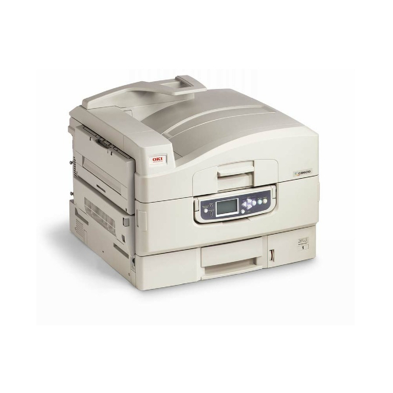
Oki C3400n User manual

Oki Data CONFIDENTIAL
C3400n
MAINTENANCE MANUAL
PRINTING SOLUTIONS

Oki Data CONFIDENTIAL
43163501TH Rev. 1 2 /
Rev.No. Date
No.
Corrected items
Page Description of change
Person in
charge
History of Revision
1 2006-04-27 ISSUE MD11 Sunaga

Oki Data CONFIDENTIAL
43163501TH Rev. 1 3 /
Preface
This manual explains the maintenance methods of C3400n.
This manual is prepared for the maintenance person. In regard to the handling methods of C3400n
please refer to the User’s Manual.
Note!
• Contents of this manual is subject to change without notice.
• While all reasonable efforts have been made to make this document as accurate
and helpful as possible, we make no warranty of any kind, expressed or implied,
as to the accuracy of the information contained herein. Oki Data assumes no
responsibility to the damages caused or claimed to have been caused by the user
as a result of repair, adjustment and/or change using this manual.
• Parts of this product are delicate and can be damaged unless properly handled. We
strongly recommend the user to maintain the product at the hand of the registered
maintenance person of our company
• Before starting the maintenance work, please neutralize the static electricity.

Oki Data CONFIDENTIAL
43163501TH Rev. 1 4 /
Table of contents
1 CONFIGURATION ............................................................................................7
1.1 System Configuration ..................................................................................................... 7
1.2 Structure of Printer.........................................................................................................9
1.3 Offer of Options ........................................................................................................... 10
1.4 Specifications ...............................................................................................................11
1.5 Interface Specification .................................................................................................. 14
1.5.1 USB Interface Specification ............................................................................ 14
1.5.1.1 Outline of USB Interface ..................................................................... 14
1.5.1.2 USB Interface Connector and Cable .................................................. 14
1.5.1.3 UBS Interface Signal .......................................................................... 14
1.5.2 Network Interface Specification ...................................................................... 15
1.5.2.1 Outline of Network Interface ............................................................... 15
1.5.2.2 Network Interface Connector and Cable ............................................ 15
1.5.2.3 Network Interface Signal .................................................................... 15
2. OPERATION DESCRIPTION .........................................................................16
2.1 Electrophotographic Process Mechanism ................................................................... 16
2.2 Printing Process ........................................................................................................... 21
3. PRINTER INSTALLATION .............................................................................31
3.2 Printer Unpacking Procedure ...................................................................................... 33
3.3 Printer Installation Instructions .................................................................................... 34
3.4 Packed Units and Attachments ................................................................................... 35
3.5 Assembly Procedure .................................................................................................... 36
3.5.1 Printer Main Body ............................................................................................ 36
3.5.2 Power Cable Connection ................................................................................. 42
3.5.3 Installation of Optional Components ............................................................... 44
3.5.4 Confirm the Recognition of Option .................................................................. 48
3.6 Status Page Print ......................................................................................................... 49
3.7 Network Information Print ............................................................................................ 50
3.8 Connection Procedures ................................................................................................ 51
3.9 Checking of User Paper .............................................................................................. 53
4. REPLACEMENT OF PARTS .........................................................................54
4.1 Precautions on the replacement of parts ................................................................... 54
4.2 Part replacement methods .......................................................................................... 56
4.2.1 Left side cover ................................................................................................. 56
4.2.2 Right side cover ............................................................................................... 57
4.2.3 Rear cover (Top/Bottom) ................................................................................. 58
4.2.4 Front cover ...................................................................................................... 59
4.2.5 Top cover assembly ......................................................................................... 60
4.2.6 Top cover ......................................................................................................... 61
4.2.7 LED assembly/ LED assembly spring ............................................................. 62
4.2.8 RFID assembly ................................................................................................ 63
4.2.9 Control pane assembly .................................................................................... 64
4.2.10 WHI board ....................................................................................................... 65
4.2.11 Feeder unit ...................................................................................................... 66

Oki Data CONFIDENTIAL
43163501TH Rev. 1 5 /
4.2.12 Manual feeder unit ........................................................................................... 67
4.2.13 Face up tray .................................................................................................... 68
4.2.14 Guide eject assembly ...................................................................................... 69
4.2.15 Eject roller ....................................................................................................... 70
4.2.16 Plate shield front .............................................................................................. 71
4.2.17 Color registration assembly ............................................................................. 72
4.2.18 Plate shield rear .............................................................................................. 73
4.2.19 PRE board (toner sensor board)/ Gear idle dram ........................................... 74
4.2.20 Main motor/ Solenoid ...................................................................................... 75
4.2.21 Belt motor/ High voltage board/ Cover open switch ........................................ 77
4.2.22 Low voltage power supply/ Low voltage fan .................................................... 78
4.2.23 BLA Board (Main Board) ................................................................................. 79
4.3 Lubricating points ......................................................................................................... 80
5. MAINTENANCE MENU ..................................................................................93
5.1 Maintenance Utility (Not Available) ............................................................................. 93
5.2 Various printing of the printer unit with controller ...................................................... 96
5.3 Switch pressing function when power supply is turned on ....................................... 96
5.4 Settings after Parts Replacement ............................................................................... 97
5.4.1 Notes when exchanging the main circuit board and
EEPROM setting after the exchange of BLA circuit board .............................. 97
5.5 About the manual setting of density correction ........................................................ 101
6. REGULAR MAINTENANCE .........................................................................102
6.1 Recommended substitutes ......................................................................................... 102
6.2 Cleaning...................................................................................................................... 102
6.3 Cleaning LED lens array ........................................................................................... 102
6.4 Cleaning the pick-up roller ........................................................................................ 104
6.5 Cleaning the inside of the printer ............................................................................. 105
7. TROUBLESHOOTING PROCEDURES .......................................................107
7.1 Precautions prior to repair ......................................................................................... 107
7.2 Items to be checked prior to taking action on abnormal images ........................... 107
7.3 Precautions when taking action on abnormal images ............................................. 107
7.4 Preparations for troubleshooting ............................................................................... 107
7.5 Troubleshooting method ............................................................................................ 107
7.5.1 LED Message List ............................................................................................ 108
7.5.2 Preparing for troubleshooting ........................................................................ 127
7.5.2.(1) LCD Display Malfunction .............................................................. 129
7.5.2.(2) Irregular Operation of the device after turning on the power ....... 130
7.5.2.(3) Paper Feed Jam (Error 391:1st tray) ........................................... 139
7.5.2.(4) Paper Feed Jam (Error 390: Multipurpose tray) .......................... 141
7.5.2.(5) Paper transport jam (Error 381) ................................................... 143
7.5.2.(6) Paper Exit Jam (Error 382) .......................................................... 148
7.5.2.(7) Paper Size Error (Error 400) ........................................................ 151
7.5.2.(8) ID Unit Up-Down Error (Service Call 140-143) ............................ 152
7.5.2.(9) Fuser Error (Error 170-177) ......................................................... 153
7.5.2.(10) Motor Fan Error(Error 127) .......................................................... 154
7.5.2.(11) Print Speed is Slow (Low Performance) ...................................... 155
Oki Data CONFIDENTIAL
43163501TH Rev. 1 6 /
7.5.2.(12) LED head is not recognized(Error 131,132,133,134) .................. 155
7.5.2.(13) Toner cartridge is not recognized (Error 540, 541, 542, 543) ...... 156
7.5.2.(14) Fuse Cut Error (Error 150-155) .................................................... 157
7.5.2.(15) Dew Condensation Errors (Error 123).......................................... 158
7.5.2.(16) RFID Related Error (Error 610-613) .............................................. 159
7.5.3 Image Problem Troubleshooting ................................................................... 160
7.5.3.(1) Color is totally pale (Figure 7.2 A ) ............................................... 161
7.5.3.(2) Background is dirty (Figure 7.2 B )............................................... 162
7.5.3.(3) Blank Print (Figure 7.2 C )............................................................ 163
7.5.3.(4) Vertical lines are printed ............................................................... 164
7.5.3.(5) Cyclic Print Trouble (Refer to Figure 7.2 E ) ................................ 165
7.5.3.(6) Color drift is wide.......................................................................... 166
7.5.3.(7) Solid Black Print ........................................................................... 167
7.5.4 Response after Flash compulsive initialization .............................................. 168
7.5.5 Network Troubleshooting ............................................................................... 169
7.6 Fuse Checking ........................................................................................................... 170
8. CONNECTION DIAGRAMS .........................................................................171
8.1 Check of resistance values ....................................................................................... 171
8.2 Component layout ...................................................................................................... 174

Oki Data CONFIDENTIAL
43163501TH Rev. 1 7 /
Figure 1-1-1
1 CONFIGURATION
1.1 System Configuration
C3400n
The system configuration of this product is shown in Figure 1-1-1.
JST12
4
FLASH
8M
Stand-by
FAN
CU
ASIC
(Spilytas)
DCON
BOURBON
JST3
Network I/F
DCON I/F
LSYNC
LEISUS
Command I/F
HEADSEL
50MHz
OPTION
RAM
34
1
PU
1st
P.E
5V, 24V
0VL,0VP
14
Color Blur,
Density,
Thermistor signal
EEPROM
20MHz
5V→3.3V
5V→1.5V
Regulator
JST14
ELC12
ASIC(ARMORED)
75Ω
12
Environment Temoerature/
Humidity Signal,
High Pressure I/F, Cover Open
Belt Unit
BELT
FUSE
ELC10
ELC10
10
ELC5
JST5
5
RFID
Operator
Panel
ELC7
JST7
7
High Voltage Power Unit
Cover
Open Sw
ENV Sensor
UP/DOWN
Sensor
AMP2
3333
K-ID Y-ID M-ID C-ID
LED
FUSE
LED
FUSE
LED
FUSE
LED
FUSE
22 2 2
Toner Sensor PCB
ID Fuse-Cut terminal
C Toner
Sensor
M Toner
Sensor
Y Toner
Sensor
K Toner
Sensor
RFID
PCB
2
2
2
2
K-
Tag
Y-
Tag
M-
Tag
C-
Tag
K-
ANT
Y-
ANT
C-
ANT
M-
ANT
Operation Panel PCB
LED1 LED2 LED3 SW1 SW2
K LED HEAD
ELC24
ELC24
Y LED HEAD
ELC24
ELC24
M LED HEAD
ELC24
ELC24
C LED HEAD
ELC24
ELC24
24
24
24
24
FAN
AC
HRS2-10
AC-SW
2
2
2
3
Low Voltage Power Unit
JST3
JST3 JST3
AC Inlet
Fuser Unit
Heater Thermistor x 4
Consumable Fuse
JST17
EL
17
Density
Sensor
5
MOLEX10
HRS2-10
FUSE
10
Temperature
Sensor
LOW-TH
FRM-TH
UP-TH
SIDE-TH
EXIT
Sensor
Rear Sensor Relay PCB
Reg-R
Sensor
AMP3
AMP3
HOP
Solenoid
JST4
AMP4AMP4
BELT
M
4
4
MOLEX6
HEAT
M
IDUP
M
AMP4
AMP5
4
JST2
2
AMP10
10
AMP4
4
ID
M
HOP
M
Reg-L
Sensor
3
MOLEX5
MOLEX5
AMP4
AMP10
AMP5
IN1
Sensor IN2
Sensor
WR
Sensor
Front Sensor PCB
AMP5
5
USB 2.0
Belt Consumable Fuse

Oki Data CONFIDENTIAL
43163501TH Rev. 1 8 /
JST12
4
FLASH
8M
Stand-by
FAN
CU
USB 2.0
ASIC
(Spilytas)
DCON
BOURBON
JST3
Network I/F
DCON I/F
LSYNC
LEISUS
Command I/F
HEADSEL
50MHz
34
1
PU
1st
P.E
5V, 24V
0VL,0VP
14
Color Blur,
Density,
Thermistor signal
EEPROM
20MHz
5V→3.3V
5V→1.5V
Regulator
JST14
ELC12
ASIC(ARMORED)
75Ω
12
Environment Temoerature/
Humidity Signal,
High Pressure I/F, Cover Open
Belt Unit
BELT
FUSE
Belt Consumable Fuse
ELC10
ELC10
10
ELC5
JST5
5
RFID
Operator
Panel
ELC7
JST7
7
High Voltage Power Unit
Cover
Open Sw
ENV Sensor
UP/DOWN
Sensor
AMP2
3333
K-ID Y-ID M-ID C-ID
LED
FUSE
LED
FUSE
LED
FUSE
LED
FUSE
22 2 2
Toner Sensor PCB
ID Fuse-Cut terminal
C Toner
Sensor
M Toner
Sensor
Y Toner
Sensor
K Toner
Sensor
RFID
PCB
2
2
2
2
K-
Tag
Y-
Tag
M-
Tag
C-
Tag
K-
ANT
Y-
ANT
C-
ANT
M-
ANT
Operation Panel PCB
LED1 LED2 LED3 SW1 SW2
K LED HEAD
ELC24
ELC24
Y LED HEAD
ELC24
ELC24
M LED HEAD
ELC24
ELC24
C LED HEAD
ELC24
ELC24
24
24
24
24
FAN
AC
HRS2-10
AC-SW
2
2
2
3
Low Voltage Power Unit
JST3
JST3 JST3
AC Inlet
Fuser Unit
Heater Thermistor x 4
Consumable Fuse
JST17
ELC17
17
Density
Sensor
5
MOLEX10
HRS2-10
FUSE
10
Temperature
Sensor
LOW-TH
FRM-TH
UP-TH
EXIT
Sensor
Rear Sensor Relay PCB
Reg-R
Sensor
AMP3
AMP3
HOP
Solenoid
JST4
AMP4AMP4
BELT
M
4
4
JST4
HEAT
M
IDUP
M
AMP4
AMP5
4
JST2
2
AMP10
10
AMP4
4
ID
M
HOP
M
Reg-L
Sensor
3
MOLEX5
MOLEX5
AMP4
AMP10
AMP5
IN1
Sensor IN2
Sensor
WR
Sensor
Front Sensor PCB
AMP5
5

Oki Data CONFIDENTIAL
43163501TH Rev. 1 9 /
Figure 1-2
1.2 Structure of Printer
The insides of C3400n printers are composed of the following parts.
• Electronic photography process part
• Paper path
• Control part (CU part/PU part)
• Operation panel
• Power supply parts (high voltage part/low voltage part)
Figure 1-2 shows the composition of the printer.

Oki Data CONFIDENTIAL
43163501TH Rev. 1 10 /
1.3 Offer of Options
This product can be installed with the following option.
(1) Additional memory board (C3400n) 64/256MB
Installation of the additional memory board is recom-
mended for banner-sheet printing.

Oki Data CONFIDENTIAL
43163501TH Rev. 1 11 /
1.4 Specifications
C3300n C3400nCategory Item
Exterior
Dimension
Width of print
Engine
speed(A4)
Fast print time
(A4)
Resolution
CPU
RAM
ROM
Power
Consumption
Operating
Environment
(temperature)
Operating
Environment
(humidity)
Width
Depth
Height
Weight
Width of print
Monochrome
Color 12ppm 16ppm
Monochrome
Color
Warm-up time
Low noise mode
LED head
Maximum input resolution
Output resolution
Step
Economic mode
Core
I-cash
D-cash
Clock
Bus width
Resident
Option
Program
Power input
Power saving mode
Idle
Normal operation
Peak
In operation
At stand-by
In storage (1 year max.)
At transport (1 month max.)
In operation
At stand-by
In storage
At transport
16ppm
12ppm
12sec
15sec
Unavailable
20ppm
16ppm
10sec
12sec
64/256MB DIMM
True 600 ×1200dpi
True 600 ×600dpi
372mm
478mm
290mm
about 21kg
A4
60sec
Unavailable
600dpi
600 ×1200dpi
4 steps 600 ×600dpi
toner saving by lowering light
PowerPC405
16KB
16KB
200MHz
32bit
32MB
total capacity 2MB
100-127VAC (Range 99-140VAC) /
220-240VAC (Range 198-264VAC)
Below 14W
100W(average)
400W
980W
10°C-32°C,17°C-27°C
(temperature at full color printing with quality guaranteed)
0°C-43°C, power off
-10°C-43°C with drum and toner
-29°C-50°C with drum and without toner
-29°C-50°C with drum and toner
20%-80%, 50%-70%
(humidity at fullcolor printing with quality guaranteed)
Max. wet bulb temperature : 25°C
10%-90%, Max. wet bulb temperature : 26.8°Cwith power off
10%-90%, Max. wet bulb temperature : 35°C
10%-90%, Max. wet bulb temperature : 40°C

Oki Data CONFIDENTIAL
43163501TH Rev. 1 12 /
C3300n C3400nCategory Item
Life
Operation
noise
Paper handling
Paper size
Min. paper size
Printer life
Duty cycle (M=L/12,A=L/12/5)
MTBF (2.3% duty)
MTBF
MTTR
Toner life
(5% duty)
mage drum life
Transcript belt life
Fuser life
In operation (ISO 7779 front)
Printing on one side
At stand-by (ISO 7779 front)
Power saving mode
Paper feeding capacity (1st tray)
Paper feeding capacity
(manual feeder)
Paper output
Legal/universal or A4 cassette/
Universal cassette
Manual feeder
1st tray
Manual feeder
30,000pages (size A4)
Automatic counter reset
6.38B (A)
legal 13/13.5/14, letter,
executive, A4, A5, B5, A6,
C5, DL, Com-9, com-10,
monarch, custom size,
government postcard, reply
paid postcard, end-opening
envelope
50,000pages (size A4)
Automatic counter reset
6.5B (A)
legal 13/13.5/14, letter,
executive, A4, A5, B5, A6, C5,
DL, Com-9, com-10,monarch,
custom size, , government
postcard, reply paid postcard,
end-opening envelope,
banner up to 1200mm (In
case length is over 356, width
would be up to 210 to 215.9)
300,000 pages or 5 years
350,000 pages per month max.
5,000 pages per month average
6,000 hours
35,000 pages
20 minutes
ODA/JPN about 1,000 pages (black)
OEL/AOS about 500pages (black)
ODA/JPN about 1,000 pages (color)
OEL/AOS about 500pages (color)
about 2,500pages (black)
about 2,000pages (color)
about 1,700pages (black)
about 1,200pages (color)
ODA about 1,500pages (black)
OEL/AOS/JPN about 1,000pages (black)
about 1,000pages (color)
ODA about 700pages (black)
OEL/AOS/JPN about 500pages (black)
about 500pages (color)
15,000 pages approx.(3 pages/ job)
9,000 pages approx.(1 page/ job)
20,000 pages approx.(at continuous print)
Automatic drum counter reset
50,000pages (size A4, 3 pages/job) Automatic counter reset
3.7B (A)
back grand level
legal/universal cassette 250 sheets (70kg)
1 sheet
150 sheets (70kg) face down/
one sheet (10 postcards) face up tray
1st cassette: legal13/13.5/14, letter, executive, A4, A5, B5,
A6, postcard
100mm ×148mm
100mm ×148mm
starter toner
(Appended)
Standard
New drum 1st one
S type
New drum 1st one

Oki Data CONFIDENTIAL
43163501TH Rev. 1 13 /
C3300n C3400nCategory Item
Paper
thickness
Operation
panel
Status
switch/Sensor
Communication
Interface
Emulation
Font
Option
(Removable)
Shipping set-
up
Others
1st tray
Manual feeder
duplex (manual)
LED (color)
Switch
Paper tray empty
Paper low
Toner low
Cover open
Fuser temp.
Paper size
Stacker full
Standard (on circuit board)
Option for OEM user
On/off switch
Standard
Emulation switch
Bit map
Type face
Scalable 1
Type face
Scalable 2
Type face
Scalable 3
Type face
Luster riser
Bar code
OCR
Japanese PCL font
Japanese PS font
RAM set
Japan
USB-IF logo
Windows logo
Operation by UPS
¥
Full-Speed USB
N/A
Hi-Speed USB
64, 256MB
64-120gsm
64-203gsm
64-105gsm
3 (Green ×1, dark amber ×2)
2
Available
N/A
Available (Y.M.C.K)
Available
Available
N/A
N/A
Ethernet
N/A
Automatic
Hiper-C
N/A
N/A
N/A
N/A
N/A
N/A
N/A
N/A
N/A
N/A
GDI model
Available
Available
Operation by UPS (outage free power supply) is not
guaranteed. (Do not use UPS)

Oki Data CONFIDENTIAL
43163501TH Rev. 1 14 /
2
34
1
Name of Signal Function
1 Vbus Power Supply (+5V) (red)
2 D - Data transmission (white)
3 D + Data transmission (green)
4 GND Signal ground (black)
Shell Shield
1.5 Interface Specification
1.5.1 USB Interface Specification (C3400n)
1.5.1.1 Outline of USB Interface
(1) Basic Specification
USB (C3400n supports Hi-Speed USB)
(2) Transmission Mode
Full speed (12Mbps±0.25% max.)
Hi speed (480Mbps±0.05% max.)
(3) Power Control
Self power device
1.5.1.2 USB Interface Connector and Cable
(1) Connector
•Printer side: B receptacle
Upstream port
Equivalent of UBR24-4K5C00 (made by ACON)
Connector pin arrangement
•Cable side: B plug (off)
(2) Cable
Cable length: Specification Cable of USB2.0 spec. of less than 5m.(less than 2m is
recommended)
(Shielded cable is used here.)
1.5.1.3 UBS Interface Signal

Oki Data CONFIDENTIAL
43163501TH Rev. 1 15 /
18
1.5.2 Network Interface Specification (C3400n)
1.5.2.1 Outline of Network Interface
Table1.5.2 Basic Specification of Network Interface (C3400n
Protocol Family Network Protocol Application
TCP/IP IPv4,TCP,ICMP,UDP LPR,RAW
SNMPv1
DHCP/BOOTP
HTTP
1.5.2.2 Network Interface Connector and Cable
(1) Connector
100 BASE-TX/10 BASE-T (automatic switch, no simultaneous use)
Connector pin arrangement
(2) Cable
Unshielded twist pair cable with RJ-45 connector (Category 5 is recommended.)
1.5.2.3 Network Interface Signal
Pin No. Signals Signal Direction Functions
1 TXD+ FROM PRINTER Send Data +
2 TXD- FROM PRINTER Send Data -
3 RXD+ TO PRINTER Received Data +
4 - - Unassigned
5 - - Unassigned
6 RXD- TO PRINTER Received Data -
7 - - Unassigned
8 - - Unassigned

Oki Data CONFIDENTIAL
43163501TH Rev. 1 16 /
-
-
-
--
-
Electrification roller
OPC drum
Power
supply
unit
2. OPERATION DESCRIPTION
2.1 Electrophotographic Process Mechanism
(1) Electronic photography Process
Electronic photography process is outlined as follows:
1. Electrification
Electric voltage is impressed on CH roller and the surface of CPC drum is electrified.
2. Exposure
LED head radiates light on the electrified surface of OPC drum following the image
signal. Electric charge on the radiated OPC drum surface abates depending on the
intensity of light and static latent image is formed on the OPC drum surface.
3. Development
Electrified toner is adhered to the static latent image on the OPC drum by static electric-
ity and a visible image is formed on the OPC drum surface.
4. Transcript
A sheet of paper is put upon the OPC drum surface and the toner image is transferred
on the paper by impressing electric charge on its back side by the transcript roller.
5. Drum Cleaning
Drum cleaning blade eliminates the remaining toner on the OPC drum after transfer.
6. Belt Cleaning
Belt cleaning blade eliminates the remaining toner on the belt.
7. Fusing
The toner image on the paper is fused by adding heat and pressure.
(2) Electrification
Electric voltage is impressed on electrification roller touching on the OPC drum surface and
thus the OPC drum surface is electrified.

Oki Data CONFIDENTIAL
43163501TH Rev. 1 17 /
-
-
-
--
---
-
LED head
Electrified roller
OPC drum
OPC drum
Paper
Power
supply
unit
LED head
-
-
-
--
---
-
-
-
-
Electrified roller
Development roller
Sponge roller
OPC drum
(3) Exposure
The light emanated from the LED head is radiated on the OPC drum surface. The electric
charge on the radiated portion of the OPC drum surface abates by intensity of the light and a
static latent image is formed on the OPC drum surface.
(4) Development
Adhere the toner to the static latent image on the drum surface and change it to the toner image.
1. The sponge roller let the toner adhere to the development roller.
2. The static latent image on the OPC drum surface is changed to a visible image by the toner.

Oki Data CONFIDENTIAL
43163501TH Rev. 1 18 /
-
-
-
--
---
-
-
-
-
-
-
-
+
-
+
-
+
-
+
-
+
-
+
-
+
-
+
-
+
-
+
-
+
-
+
-
+
-
+
-
+
-
+
-
+
OPC drum
Transcript roller
Paper
Transport belt
Power
supply
unit
(5) Transcript
A sheet of paper is placed under the OPC drum surface and is given electric charge from the
back side by the transcript roller. When a high voltage is impressed on the transcript roller, the
electric charge generated by the transcript roller moves over to the paper surface at the
interfacing part of the transcript roller and the toner is absorbed to the paper surface from the
OPC drum surface.

Oki Data CONFIDENTIAL
43163501TH Rev. 1 19 /
C3400 (belt fusing method)
Thermostat
Thermistor
Heat roller
Halogen lamp
Paper
Pad
Thermistor
Backup roller
Belt
Backup roller
Thermistor
Heat roller
Thermostat
Thermistor
Halogen lamp
Paper
C3300 (roller fusing method)
Paper Type Setting
Light
Medium
Heavy
U.Heavy
Paper Thickness
Thin
Thick
Temperature Setting
Middle temp.
High temp.
Middle temp.
Low temp.
Setting of Fusing Temperature
(6) Fusing
The toner image transferred on the paper is impressed with heat and pressure and is fused to
the paper when the paper passes through the heat roller and the back-up roller.
Further, a thermostat is equipped for the safety’s sake and if the temperature of the heat roller
rises above a certain degree, the thermostat opens and shuts the power supply to the heater.

Oki Data CONFIDENTIAL
43163501TH Rev. 1 20 /
Waste toner area
Drum cleaning blade
ID unit
Toner cartridge
Belt waste toner box
Belt cleaning blade
Transport belt
(7) Drum Cleaning
The toner not transferred and remaining on the OPC drum is scraped away by the drum
cleaning blade and is collected in the waste toner area of the toner cartridge.
(8) Belt Cleaning
The toner remaining on the transcript belt is scraped away by the belt cleaning blade and is
collected in the waste toner box of the transcript belt unit.
Other manuals for C3400n
8
Table of contents
Other Oki Printer manuals

Oki
Oki C7350hdn User manual

Oki
Oki 1220n User manual

Oki
Oki C3200n User manual

Oki
Oki B4100 User manual

Oki
Oki 10i User manual

Oki
Oki OKIPAGE14e Use and maintenance manual

Oki
Oki OKIOFFICE 1200 Installation and operation manual

Oki
Oki ML320 Epson/IBM User manual

Oki
Oki C9200n User manual

Oki
Oki OKIPAGE 8c Plus User manual