Oki OKIPAGE 8iM User manual

41260201TH Draft 1 / 106
OKIPAGE
8iM
LED Page Printer
Maintenance Manual
ODA/OEL
Draft Version

41260201TH Draft 2 /
Rev.No. Date No.
Corrected items
Page Description of change Person in
change
1ISSUE E2 Nagahashi

41260201TH Draft 3 /
PREFACE
This Maintenance Manual describes the field maintenance methods for LED Page Printers.
This manual is written for use by service persons. Please note that you should refer to the Printer
Handbook for the handling and operating methods of the equipment.

41260201TH Draft 4 /
CONTENTS
1. CONFIGURATION ......................................................................................... 6
1.1 System Configuration ............................................................................... 6
1.2 Printer Configuration................................................................................. 7
1.3 Specification ............................................................................................. 8
1.4 Safety Standards ...................................................................................... 10
1.4.1 Certification Label............................................................................................ 10
1.4.2 Warning Label ................................................................................................. 10
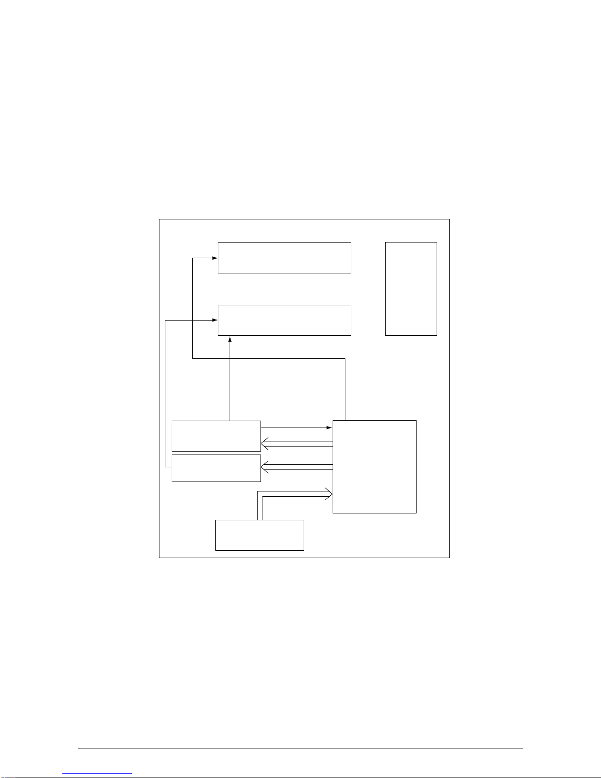
2. OPERATION DESCRIPTION......................................................................... 11
2.1 Main Control Board................................................................................... 13
2.2 Power Supply Unit .................................................................................... 14
2.3 High-Voltage Power Supply Board ........................................................... 14
2.4 Electro-Photographic Processor............................................................... 16
2.5 Electro-Photographic Process .................................................................. 20
2.5.1 Explanation of Each Process Operation.......................................................... 22
2.6 Paper Jam Detection ................................................................................ 27
2.7 Toner Low Detection................................................................................. 29
2.8 Cover Open .............................................................................................. 31
2.9 Detecting I/D Unit existence ..................................................................... 31
3. PARTS REPLACEMENT ............................................................................... 34
3.1 Precautions for Parts Replacement.......................................................... 34
3.2 Parts Layout.............................................................................................. 36
3.3 Replacing Parts ........................................................................................ 39
3.3.1 Hopper Plate ................................................................................................... 39
3.3.2 LED Head and Head Spring............................................................................ 40
3.3.3 Transfer Roller................................................................................................. 41
3.3.4 How to remove Cover Upper Assy .................................................................. 42
3.3.5 Upper Cover Assy ........................................................................................... 43
3.3.6 High-Voltage Power Supply Board (P2H) ....................................................... 44
3.3.7 Top Cover Assy and Flat Cable Assy.............................................................. 45
3.3.8 Paper Holder ................................................................................................... 46
3.3.9 Side Plate M and Idle Gear ............................................................................. 47
3.3.10 Heat Assy ........................................................................................................ 48
3.3.11 Drive Shaft E (Eject) and Eject Roller ............................................................. 49
3.3.12 Pressure Roller B (Back Up Roller)................................................................. 50
3.3.13 Separator Guide .............................................................................................. 51
3.3.14 Pulse Motor (Main) .......................................................................................... 53
3.3.15 Hopping Shaft Assy......................................................................................... 54
3.3.16 Regist Roller.................................................................................................... 55
3.3.17 Paper Sensor E, Paper Sensor Exit and Toner Sensor Assy ......................... 56
3.3.18 Base Plate ....................................................................................................... 57
4. ADJUSTMENT ............................................................................................... 58
4.1 Adjustment Types and Functions ............................................................. 58
4.1.1 Printer Driver ................................................................................................... 58
4.1.2 Engine Maintenance Utility.............................................................................. 58

41260201TH Draft 5 /
4.2 Adjustment When Replacing a Part.......................................................... 59
4.2.1 Setting LED Head Drive Time ......................................................................... 59
4.2.2 Uploading and Downloading EEPROM Data .................................................. 60
5. PERIODICAL MAINTENANCE ...................................................................... 61
5.1 Periodical Replacement Parts .................................................................. 61
5.2 Cleaning.................................................................................................... 61
5.2.1 Cleaning the LED Lens Array.......................................................................... 61
6. TROUBLESHOOTING PROCEDURES......................................................... 63
6.1 Troubleshooting Tips ................................................................................ 63
6.2 Check Points Before Correcting Image Problems .................................... 63
6.3 Notes When Correcting Image Problems ................................................. 63
6.4 Preparation Before Troubleshooting......................................................... 63
6.5 Troubleshooting........................................................................................ 64
6.5.1 Status Monitor Message List ........................................................................... 64
6.5.2 Status Message Troubleshooting.................................................................... 68
6.5.3 Image Troubleshooting.................................................................................... 74
7. WIRING DIAGRAM ....................................................................................... 83
7.1 Interconnect Signal Diagram .................................................................... 83
7.2 PCB Layout............................................................................................... 85
7.2.1 Main Control Board (HBX PCB) ...................................................................... 85
7.2.2 High-Voltage Power Supply Board.................................................................. 85
8. PARTS LIST................................................................................................... 86
APPENDIX A LOCAL PRINTING / DEMO PAGE PRINTING ....................... 93
APPENDIX B PARALLEL INTERFACE ........................................................ 95
APPENDIX C MACINTOSH INTERFACE...................................................... 97
APPENDIX D USB INTERFACE (BY USB PRINTER CABLE)..................... 99
APPENDIX E MAINTENANCE UTILITY MANUAL ...................................... 100

41260201TH Draft 6 /
Electro-photographic
Processor
Paper Feed Mechanism
ENGINE UNIT
Hopper
Plate
Main High-Voltage
Power Supply Board
Sub High-Voltage
PowerSupply Board
Power Supply Unit
Main Control Board
Figure 1-1
1. CONFIGURATION
1.1 System Configuration
The OKIPAGE 8iM consists of a control block, a power supply unit, and an engine block. (See
Figure 1-1.)

41260201TH Draft 7 /106
I/D Unit (Type 6)
Upper Cover Assy
Top Cover Assy
Heat Assy
Main Control Board
High-voltage Power
Supply Board (P6L)
High-voltage Power
Supply Board (P2H)
1.2 Printer Configuration
The printer unit consists of the following five hardware components:
• Electro-Photographic Processor
• Paper Feeder
• Main Control Board
• High-Voltage Power Supply Board (two Boards)
• Power Supply Unit
Figure 1-2 is the configuration of the printer unit.
Figure 1-2

41260201TH Draft 8 /106
1.3 Specification
(1) Type Desktop
(2) Outside dimensions Height 6.7” (170 mm)
(excludes protruding Width 12.8” (324 mm)
portion) Depth 8.1” (207 mm)
(3) Weight 4.2 kg (with Image Drum Cartridge and Toner Cartridge)
(4) Development method Dry non-magnetic development system
Exposure method LED stationary head
(5) Paper used <Type>
• Standard paper
– Xerox 4200 (20 lbs)
• Application paper (manual face-up feed)
– Label
– Envelope
– OHP paper (Transparency)
<Size>
14" (355.6 mm) x 8.5" (215.9 mm) (Max.)
5" (127mm) x 3" (76.2mm) (Min.)
<Thickness>
– Automatic feed: 16 to 28 lbs (60 to 105 g/m2)
– Manual feed: Label,Envelope, OHPpaper (transpar-
ency), 16 to 32 lbs (60 to 120g/m2)
(6) Printing speed First print: 13 seconds (A4) (after warm-up)
Continuous print: 8.1 sheets/minute (Letter)
7.7 sheets/minute (A4)
Warm-up time: 35 seconds (120 VAC for ODA, 230
VACforOEL/INT)(atroomtemperature
77 ˚F (25 ˚C))
(7) Paper feeding method Automatic paper feed or manual paper feed
(8) Paper delivery method Face up
(9) Resolution 600 dpi x 600 dpi
(10)Power input 230 VAC ±10% (for OEL)
120 VAC +6%, -15% (for ODA)
(11)Power consumption Peak: Approx. 450W
Typical operation: Approx. 160W
Idle: Approx. 32W
Power save mode: Approx. 6W

41260201TH Draft 9 /106
(12)Temperature and humidity
Temperature
During operation
In storage
10 to 32 ˚C
–10 to +43 ˚C
20 to 80% RH (relative humidity)
10 to 90% RH (relative humidity)
No condensation is permissible.
Humidity
Caution:
TemperatureandhumidityinstoragearemeasuredwiththeOKIPAGE8iMbeing
packed; they are valid for one year.
(13)Noise During operation: Avg. 50 dB (A), slow (without peak sounds)
(conformity with ANSI) Standby: Background level
(14)Consumables Toner cartridge kit 1,500 (5% duty) ........ 45g cartridge kit
Image drum cartridge 10,000 (at continuous printing)

41260201TH Draft 10 /106
1.4 Safety Standards
1.4.1 Certification Label
The safety certification label is affixed to the following location of the OKIPAGE 8iM
1.4.2 Warning Label
Warning labels are affixed to the locations that may cause bodily injury.
During maintenance, do work with enough care while following instructions on these warning
labels.
For OEL
For ODA, OEL

41260201TH Draft 11/106
2. OPERATION DESCRIPTION
TheOKIPAGE8iMconsistsofamaincontrolboard,twohigh-voltagepowersupplyboard,apower
supply unit, and an electro-photographic processor. The OKIPAGE 8iM receives print data from
a higher-level interface and sequentially stores it in memory. The OKIPAGE 8iM decodes and
edits the received data while storing print data from the interface in memory. It sequentially
transfers the edited data to the LED head for each dot line. The electro-photographic processor
then prints the data on sheets of paper.
The display of the higher-level host is used for device operation and status display.
Figure 2-1 is the block diagram of the OKIPAGE 8iM.

41260201TH Draft 12 /106
CPU
(nX8)
DRAM
2MB
EPROM
64KB
Serial I/F
Parallel
I/F
USB
I/F
Macintosh
I/F
DRAM Bus
(Data : 4)
(Address : 11)
High Voltage Power Unit
P6L
High Voltage Power Unit
P2H
EEPROM
1kb
Motor Driver
MTD2005F
OSC
16MHz HC125
LS373
RST
CN10CN1
ID Unit
CN7
Motor
HEAD2HEAD1CN8
PLUNGER LED HEAD
CN2
0VP0V
0V5V
+5V+26V
LS07
DS8925
CN4
USB
Printer
Cable
CN5
Power Supply Unit
Figure 2-1 Block Diagram

41260201TH Draft 13 /106
2.1 Main Control Board
The main control board consists of a one-chip CPU, a program ROM, a DRAM, an EEPROM, a
host interface circuit, and a mechanism driving circuit. The mechanism driving circuit consists of
a LED head, a main motor, and an electromagnetic clutch.
(1) One-chip CPU
The one-chip CPU is a custom CPU (8-bit internal bus, 8-bit external bus, 16-MHz clock)
incorporating mask ROM and CPU peripheral devices. This CPU has the functions listed in
the table below.
Controls DRAM.
Built-in Device Function
DRAM controller
Transfers image data from Parallel I/F to DRAM, from DRAM to a video output port and
between CPU and DRAM.
Video output port
LED STB output port
Generates various control timings for monitoring paper feeding and a paper size.
Inputs the feedback signals from a high-voltage generation circuit and thermistor signal.
DMA controller
Parallel interface controller
Timer
I/O port
A/D converter
Controls the parallel interface.
Controls LED head.
Inputs and outputs the sensor signals and motor signals, etc.
Also performs I/O for EEPROM.
(2) Program ROM
Program ROM contains a program for the equipment. EPROM is used as program ROM.
For details PCB Layout see Section 7.2.2.
(3) DRAM
DRAM is used as resident memory.
(4) EEPROM
EEPROM holds the following data:
• Menu data
• Counter value
• Adjustment value
(5) Parallel interface
The parallel interface receives parallel data from the host; it conforms to the Centronics
specification. IEEE-1284 B: – directional parallel is supported.
(6) Macintosh interface
Macintosh interface receives serial data from the host.

41260201TH Draft 14 /106
Used to generate a logic circuit and a high voltage.
Used to drive the motor and electromagnetic clutch.
Output voltage Application
+5 V
+26V
Output Application
CH
DB
SB
CB
TR
Voltage
–1.3 KV
–265 V/+265 V
–550 V/ 0 V
+400 V/–1.35 KV
+500 V ~ +3.5 KV/–750 V
Voltage to be applied to a charge roller.
Voltage to be applied to a developing roller.
Voltage to be applied to a sponge roller.
Voltage to be applied to a cleaning roller.
Voltage to be applied to a transfer roller.
Remarks
P2H-PCB
P2H-PCB
P2H-PCB
P6L-PCB
P2H-PCB
2.2 Power Supply Unit
The power supply unit supplies +5 V and +26 V to the main control board according to 230 VAC /
120 VAC.
The power supply unit also contains a heater drive circuit.
2.3 High-Voltage Power Supply Board
(1) High-Voltage power supply circuit
The high-voltage power supply circuit generates the following voltages required for the
electro-photographic processor from +5 V according to the control sequence from the main
controlboard. When thecoveris open,+5 Vsupplyis automaticallyinterrupted tostophigh-
voltage output.
Caution:
The TR voltage varies with medium and transfer roller impedance.

41260201TH Draft 15 /106
Figure 2-2
(2) Sensors
The high-voltage power supply board consists of the high-voltage power supply circuit that
supplies power to the electro-photographic processor system and the photosensor that
detects a paper feeding system and toners.
Figure 2-2 shows the sensor layout drawing.
Sensor Function Sensing State
Manual feed
sensor ON: Paper exists.
OFF: No paper exists.
Monitors whether paper was inserted into the manual feed sensor
section.
Detects the leading part of the paper.
Monitors paper feeding.
Monitors paper feeding and the paper size according to the paper
sensor arrival and passing time.
Detects the low toner status.
Paper sensor
Outlet sensor
Toner sensor
ON: Paper exists.
OFF: No paper exists.
ON: Paper exists.
OFF: No paper exists.
ON (long): Toner low
OFF (short): Toner High
Exit roller
Outlet sensor
Heat roller
Transfer roller
Feed roller
Toner
sensor
assy Manual feed sensor
Paper sensor
Hopping
roller
Paper feeding direction

41260201TH Draft 16 /106
2.4 Electro-Photographic Processor
The electro-photographic processor prints out the image data to be sent from the main control
board on sheets of paper. Figure 2-3 shows the layout drawing of the electro-photographic
processor.
(1) Image drum unit
Theimagedrumunitmakesatoneradheretotheformedelectrostaticlatentimagewithstatic
electricity. This electrostatic latent image is formed by the lights irradiated from LED heads.
(2) Electromagnetic clutch
The electromagnetic clutch controls the rotation of the hopping roller according to signals
from the control block.

41260201TH Draft 17 /106
Figure 2-3 Layout Drawing of Electro-Photographic Processor
Exit roller
Heat roller
(ø 19.910)
6.85
10 OFF
ON
26.50
Outlet sensor
Cleaning roller
(ø 9.000)
Charge roller
(ø 9.000)
6.77
LED head
Drum roller
(ø 16.000)
Developing roller
(ø 14.000)
17.23
12.72
23.18
20.32
64.60
Single tray
Transfer roller
(ø 15.000)
Hopping roller
OFF
32.00
10
Tray printing
10
ON OFF
Manual feed sensor
Manual printing
Feed roller
Paper sensor

41260201TH Draft 18 /106
Main Motor Electromagnetic Clutch
OFF
ON
Hopping Roller
Non-rotation
Rotation
Non-rotation
Regist Gear Drum Gear Operation
Warm-up
Hopping
Prinitng
Non-rotation
Rotation
Rotation
Rotation
Rotation
Rotation
Normal rotation
Reverse rotation OFF
(3) Pulse motor (Main)
Thispulsemotorof48steps/rotationistwo-phaseexcitedbythesignalfromthemaincontrol
board;itperformsfeedingcontrolbyswitchingnormalrotationtoreverserotationorviceversa
and turning on/off the electromagnetic clutch. The relationship between the main motor,
electromagneticclutch,resistgear,drumgear,hoppingrollerisshowninthetablebelowand
on the subsequent pages.
(4) LED head
Theshiftandlatchregistersreceiveimagedatafromthemaincontrolboardforeachdotline.
4,992 LEDs are driven to radiate the image drum.
(5) Heat Assy
The heat Assy consists of a heater, a heat roller, a thermistor, and a thermostat.
The power supply unit supplies AC voltage to the heater according to the HEATON signal
fromthe maincontrol boardto heatthe heatroller. The maincontrolboardmonitorstheheat
rollertemperatureviathethermistorandkeepsthetemperatureconstantbyturningon/offthe
heater AC voltage supply.
If the heat roller temperature rises abnormally, the thermostat of the heater voltage supply
circuit functions to forcibly suspend the AC voltage supply.

41260201TH Draft 19 /106
Figure 2-4 Schematic Drawing of OKIPAGE8iM Paper Feeding
Exit roller
Heat roller
Transfer roller
Cleaning roller
CH roller
Drum roller
Developing roller
Outlet
sensor
Paper sensor
Hopping roller
TRAY printing
Feed roller
Manual
feed
sensor
Manual printing
2Roller to be driven by reverse
rotation of pulse motor (Main) 1Motor to be driven by normal
rotation of pulse motor (main)
Roller control by pulse motor (main)
1Normal rotation of pulse motor (main): Drum roller, transfer roller, cleaning roller, CH roller, developing roller, heat roller, exit roller rotation
2Reverse rotation of pulse motor (main): Drum roller, transfer roller, cleaning roller, CH roller, developing roller, heat roller, exit roller, feed roller,
hopping roller rotation
Hopping operation from the tray, however, is performed when the electromagnetic clutch is turned on.

41260201TH Draft 20 /106
2.5 Electro-Photographic Process
(1) Electro-photographic process
The electro-photographic process is outlined below.
1Charging
The surface of the OPC drum is charged negatively and uniformly by applying the DC
voltage to the CH roller.
2Exposure
Light emitted from the LED head irradiates the negatively charged surface of the OPC
drum. Thesurfacepotentialoftheirradiatedsurfaceattenuatestoformthe electrostatic
latent image corresponding to the image signal.
3Development and residual toner recovery
Thenegativelycharged tonerisbroughtintocontactwiththeOPCdrum,adhering tothe
electrostatic latent image on the OPC drum by static electricity. This adhesion causes
the electrostatic latent image to change to a visible image.
At the same time, the residual toner on the OPC drum is attracted to the developing
rollerby static electricity.
4Transfer
Whenpaperisplacedovertheimagedrumsurface,thepositivechargewhichisopposite
inpolaritytothatofthetoner,isappliedtothereversesidebythetransferroller.Thetoner
is attracted by the positive charge and is transferred onto the paper. This results in the
transfer of the toner image formed on the image drum onto the paper.
5Cleaning
The cleaning roller temporarily attracts the residual toner on the transferred OPC drum
with static electricity, then returns the toner to the OPC drum.
6Fusing
The transferred unfused toner image is fused to a sheet of paper by applying heat and
pressure to the image.
Figure 2-5 is a flow for the electro-photographic process.
Table of contents
Other Oki Printer manuals
Popular Printer manuals by other brands

Epson
Epson Stylus Pro 4880 ColorBurst Edition - Stylus Pro 4880... user guide

Pitney Bowes
Pitney Bowes Datamax w1110 Installation instruction

Printek
Printek FormsPro 4300 owner's manual

Supvan
Supvan TP2000M user manual

MUTOH
MUTOH Rockhopper II Series Maintenance manual

Epson
Epson Stylus Pro 7900 user guide