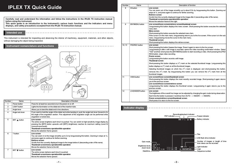
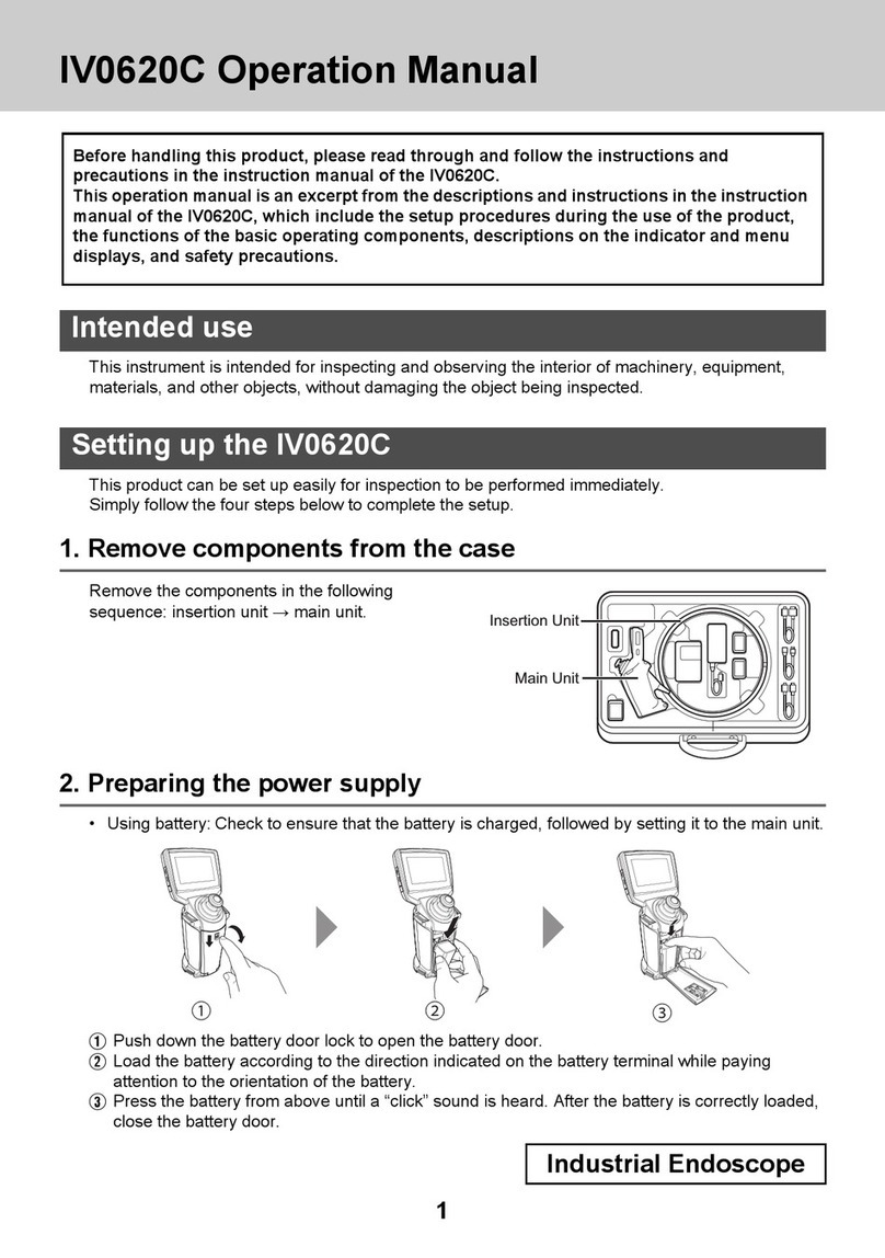
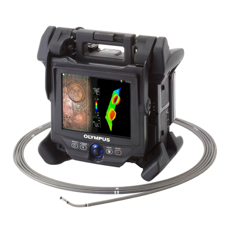
Olympus IPLEX RX Series User manual

INSTRUCTIONS
INDUSTRIAL VIDEOSCOPE
IPLEX RX series
IPLEX RT series
IV9620RX
IV9635RX
IV9650RX
IV9675RX
IV9420RX
IV9435RX
IV9620RT
IV9635RT
IV9650RT
IV9675RT
IV9420RT
IV9435RT

Shinjuku Monolith, 3-1 Nishi-Shinjuku 2-chome, Shinjuku-ku, Tokyo 163-0914, Japan
Telephone: +81 3 6901 4038
48 Woerd Avenue, Waltham, MA 02453, U.S.A.
Telephone: +1 781 419 3900
L43, Office Tower, Langham Place, 8 Argyle Street, Mongkok, Kowloon, Hong Kong
Telephone: +852 2481 7812
Wendenstrasse 14-18, 20097 Hamburg, Germany
Telephone: (49)40-23-77-30
Telephone: +61 130 013 2992
3 Acacia Place, Notting Hill VIC 3168, Australia

i
Contents
Introduction ............................................................................................1
Intended use ....................................................................................................................... 1
Instruction manual .............................................................................................................1
Product configuration........................................................................................................ 1
Expanded functions of the IPLEX RX/RT series ............................................................. 1
Important Information–Please Read Before Use.................................1
Marks used in this manual ................................................................................................ 1
Safety precautions.............................................................................................................2
General safety precautions ..................................................................................... 2
Battery precautions ................................................................................................. 5
Rating plate/caution plate......................................................................7
1 Unpacking 8
1.1 Unpacking the instrument ..................................................................................... 8
About options ........................................................................................................ 8
2 Nomenclature 9
2.1 Main unit/control unit nomenclature .................................................................... 9
2.2 Distal end/optical adapter nomenclature ........................................................... 11
4-mm type ............................................................................................................ 11
6-mm type ............................................................................................................ 11
2.3 LCD monitor nomenclature ................................................................................. 12
Live screen........................................................................................................... 12
Thumbnail screen................................................................................................ 12
Retrieve screen.................................................................................................... 12
3 Pre-observation/pre-operation preparation and inspection 13
3.1 Pre-observation preparation ............................................................................... 13
Preparing the power supply ............................................................................... 13
3.2 Pre-operation preparation ................................................................................... 15
Attaching the optical adapter............................................................................. 15
Turning on power ................................................................................................ 16
Selecting the optical adapter ............................................................................. 16
Checking the remaining battery level................................................................ 17
Checking lighting of illumination at the insertion tube's distal end............... 18
Checking the angulation operation of the insertion tube................................ 18
Attaching the USB flash drive............................................................................ 19
Setting up the main unit and performing observation..................................... 19
Attaching the shoulder strap ............................................................................. 21
Mounting of the control unit on the main unit.................................................. 22
Securing the insertion tube to move the instrument to another location...... 24
Attaching the optical adapter case holder........................................................ 24
3.3 Pre-operation/post-operation inspections ......................................................... 25
4 Basic operation 27
4.1 Viewing an observation object............................................................................ 27
4.2 Adjusting the image display................................................................................ 29
Still image display (Freeze) ................................................................................ 29
Enlarging an image (Zoom) ................................................................................ 29
Adjusting image brightness ............................................................................... 30
4.3 Switching the folder from the live screen .......................................................... 31

ii
4.4 Recording images ................................................................................................ 32
Image recording preparation.............................................................................. 32
Recording a still image ....................................................................................... 33
Recording a movie image................................................................................... 34
Appending a moving image (RX only)............................................................... 35
4.5 Replaying an image.............................................................................................. 36
Playing back on a full-screen view (retrieve screen) ....................................... 36
Multi-image view (thumbnail screen) ................................................................ 37
4.6 Displaying a PDF file (RX only) ........................................................................... 38
Preparing a PDF file ............................................................................................ 38
Displaying a PDF file........................................................................................... 38
4.7 Displaying live images on an external monitor ................................................. 39
4.8 Using recorded images on a PC ......................................................................... 39
5 Menu operations and functions 40
5.1 Performing menu operations .............................................................................. 40
5.2 Using the live screen/freeze screen.................................................................... 41
Menu display and functions ............................................................................... 41
Inputting a title..................................................................................................... 44
Registering a character string as a preset title ................................................ 45
Adjusting image sharpness (RX only)............................................................... 46
Adjusting image saturation (RX only) ............................................................... 46
Setting the date and time.................................................................................... 47
Changing the display language ......................................................................... 47
5.3 Using the thumbnail/retrieve screens ................................................................ 48
Menu display and functions ............................................................................... 48
5.4 Operations in the PDF file display screen (RX only)......................................... 49
Menu items and functions .................................................................................. 49
6 Stereo measurement procedures
(RX (stereo measurement function)
only) 51
6.1 Measurement Flow ............................................................................................... 52
6.2 Attaching the stereo optical adapter .................................................................. 53
6.3 Registering the new stereo optical adapter
or re-registering the stereo optical adapter.......................................................54
Registering the new stereo optical adapter...................................................... 54
Re-registering the stereo optical adapter ......................................................... 56
6.4 Selecting the registered stereo optical adapter ................................................ 57
6.5 Checking measurement values........................................................................... 58
6.6 Capturing measurement area.............................................................................. 60
Observing measurement area............................................................................ 60
Measuring the distance to the measurement area by spot ranging............... 61
6.7 Measurement ........................................................................................................ 63
Measurement ....................................................................................................... 63
Measurement screen........................................................................................... 64
Measurement method types............................................................................... 66
Specification of measurement points ............................................................... 67
7 Storage and maintenance 68
7.1 Replacing the battery...........................................................................................68
7.2 Replacing the O-ring ............................................................................................ 68
7.3 Cleaning components .......................................................................................... 68
Cleaning the insertion tube ................................................................................ 68
Cleaning the distal end ....................................................................................... 69
Cleaning the optical adapter .............................................................................. 69
Cleaning the LCD monitor .................................................................................. 70
iii
Cleaning the main unit and control unit............................................................ 70
7.4 Storage precautions............................................................................................. 70
8 Troubleshooting 71
8.1 Troubleshooting guide......................................................................................... 71
Error messages ................................................................................................... 71
Common problems.............................................................................................. 72
8.2 Requesting repair of this product....................................................................... 74
9 Specifications 75
9.1 Operating environment ........................................................................................ 75
9.2 Other specifications ............................................................................................. 75
External application standard ............................................................................ 78
Software license information ............................................................................. 78
9.3 Optical adapter specifications ............................................................................ 79
For 4-mm type insertion tube............................................................................. 79
For 6-mm type insertion tube............................................................................. 79
Appendix ...............................................................................................80
System chart ...................................................................................................................80

iv

1
Introduction
Intended use
This instrument is intended for inspecting and observing the interior of machinery, equipment, ma-
terials, and other objects, without damaging the object being inspected.
Instruction manual
This manual contains information about instrument operations and handling, which makes it pos-
sible for the instrument to be used safely.
Before using the instrument, carefully read the contents of this manual to ensure that you use the
instrument correctly. After reading the manual, store it and the warranty agreement in a safe place.
If you have any questions about any information in this manual, please contact Olympus.
Product configuration
For information about the configuration of devices required by this product and devices that can be
used in combination with it, see "System chart" (P. 80) in the "Appendix".
Note that use of this product in combination with options and separately available items not only
creates the risk of abnormal operation, it also can damage the product.
Expanded functions of the IPLEX RX/RT series
The IPLEX RX/RT series functions can be expanded.
IPLEX RT →IPLEX RX
IPLEX RX →IPLEX RX (Stereo measurement function)
Contact Olympus for details.
Important Information–Please Read Before Use
Marks used in this manual
The following signal words are used throughout this manual.
DANGER
WARNING
CAUTION
CAUTION
●Indicates an imminently hazardous situation which, if not avoided, will result in death, serious injury or
damage of observation object.
●Indicates a potentially hazardous situation which, if not avoided, could result in death, serious injury
or damage of observation object.
●Indicates a potentially hazardous situation which, if not avoided, may result in minor or moderate
injury. It may also be used to alert against unsafe practices or potential material damage.
●Indicates a potential situation which, if not avoided, may result in failure of this instrument.
●Indicates additional helpful information.
NOTE

2
General safety precautions
Safety precautions
Observe the precautions described below when handling the instrument. The information is to be
supplemented by the dangers, warnings and cautions given in each chapter. Safety cannot be
guaranteed when the instrument is used in ways that are not specifically described.
DANGER
WARNING
CAUTION
●Never use this instrument for observation inside a human or animal cavity.
Otherwise, death of the person or animal may result.
●Never use the instrument in the following types of environments.
- Where flammable atmospheres are present
- Where metal dust or other dust is present
Otherwise, an explosion or fire may result.
●Do not repair, disassemble, or modify the instrument.
This instrument does not contain any user serviceable parts. Do not disassemble, modify
or attempt to repair. User injury and/or equipment damage can result. Olympus is not liable
for any accidents or instrument damage that occurs as a result of repairs attempted by non-
Olympus personnel.
Contact Olympus for all repair and servicing.
●Immediately stop using the instrument at the first sign of smoke, abnormal odor, abnormal
noise, or any other abnormality.
Even if operation of the instrument is still possible, turn off power.
●Do not insert the insertion tube into an observation object that is in operation or conducting electricity.
Otherwise the insertion tube may be damaged by being caught inside of the observation
object, etc., or the insertion tube may touch the object, resulting in electric shock.
●Before stowing the instrument in its carrying case, be sure to turn off power and remove the
battery. Leaving the battery loaded during storage can cause it to become hot, causing the
risk of fire.
●Do not use this instrument in any environment (including strongly radioactive environments)
that does not conform to the specified operating environment.
Otherwise, unexpected accidents that may damage the insertion tube may result.
●If you carry this instrument to the high altitude or use at the high altitude, be careful for followings.
- Check the instrument prior to use.
- Prevent the instrument from dropping.
- Make sure of the safety thoroughly.
●Do not insert the insertion tube into an observation object in an environment that is outside
the operating temperature range.
Continued use may damage or reduce the performance of the instrument.
●Do not touch the distal end immediately after using this instrument in high-temperature environments.
Otherwise, you may get burned.
●Do not grip the control unit for long periods while using it in very hot environments.
Doing so may lead to low-temperature burns. Wear gloves or do something to prevent low-
temperature burns.
●Use only a power cord and AC adapter specified by Olympus and connect the power cord to
a 3P power outlet in rated range
Otherwise, smoke, fire, or electric shock might occur.
●Do not use the AC adapter outdoors.
Otherwise, electric shock might occur, or smoke emission and fire might occur, causing dam-
age to the instrument.
The AC adapter is designed for indoor use.

3
●Do not subject the AC adapter to strong impact cause by striking it against a wall, dropping it, etc.
Otherwise, malfunction, damage, or electric shock might occur.
●Should you sense any abnormality while inserting the scope into the object to be inspected,
do not try to force the operation and carefully withdraw the insertion tube. Note the following
precautions when withdrawing the insertion tube.
- Do not try to withdraw from the observation object while angulation is locked or while the
angulation section is bent.
- If the insertion tube becomes caught on something during withdrawal, rotate the control
unit gently while continuing the withdrawal.
●Note the following precautions during handling the insertion tube's distal end.
- Do not drop the optical adapter or otherwise subject it to strong impact.
- Do not subject the distal end to severe impact or pulling.
- Do not expose the angulation section to severe impact or bending.
Otherwise, glass lenses and the precision components that make up the distal end and the
angulation section might be damaged.
●Never use the instrument without an optical adapter mounted.
Otherwise, parts (screws, etc.) are easily subjected to deformation due to contact with hard
objects, etc. Deformed insertion tube parts can make it no longer possible to mount an opti-
cal adapter and can cause the optical adapter to fall off.
●Never use an optical adapter when any of its parts are loose.
Otherwise, a loose part might fall into the inspection object.
●The optical adapters have a safe double-screw installation design. However, if an optical
adapter starts to come off the distal end while inserting the scope into the object to be in-
spected, the entire or a part of the observed image may be whitish caused by the illumination
light or a part of the view field may be lacked. The optical adapter may fall off the insertion
tube's distal end if used in this condition. In this case, immediately stop the inspection, care-
fully withdraw the insertion tube and secure the optical adapter as described in"Attaching the
optical adapter" (P. 15).
Tip adapter not
properly attached
(The strong light appears partially.)
The screen is viewed whitish.
The entire screen is
clearly viewed.
Correct
●Should you sense any abnormality when performing angulation operation, do not try to force
the angulation operation.
Doing so can damage the insertion tube or observation object.
●Never use the instrument while dirt or water is present in the optical adapter
Water tightness between the optical adapter and the distal end may be lost, or the optical
adapter or the distal end may be damaged.
●If an optical adapter cannot be mounted or removed because the nut will not turn, stop using it.
Contact Olympus.
●Do not look directly into the illumination being emitted by the distal end.
Otherwise, eye damage may result.
●Take care not to have your feet caught by a cord including the power cord or universal cable.
●When hanging the main unit from your neck by the shoulder strap, do not allow it to catch on
other objects. Be careful that it does not choke you.
●Do not allow metal or other foreign objects to enter the main unit through connectors or any
other openings.
Otherwise, a malfunction or electric shock may result.
●Do not use the parts other than the insertion tube in water or clean them under running water.
Water creates the risk of electric shock. The parts other than the insertion tube are designed for
water resistant proof construction only if the battery cover and connector caps are closed com-
pletely. Do not use or store the instrument under the environment where it is submerged or wet.

4
●Never connect any other USB device or USB cable to the USB connector except for the USB
flash drive provided as standard or USB Flash Drive recommended by Olympus.
●Do not remove the battery or AC adapter while the system is running.
Otherwise, recorded data may be damaged.
●Do not remove the USB flash drive while recording or replaying the image.
Otherwise, recorded data may be damaged or lost.
CAUTION
●Do not continue to use the instrument when it is wet with condensation.
Sudden temperatures changes such as those that occur when entering a warm room from
the outside cold can cause condensation to form inside the instrument. Using the instrument
while it is wet with condensation can cause malfunction. If condensation forms, leave the
instrument in the environment where it is to be used and allow the condensation to dry before
using it.
●Do not cover the main unit with a plastic bag or other object during use.
If the inside of the instrument cannot be cooled, the instrument damage may result.
●Do not allow any liquids other than water, saltwater, machine oil, or diesel oil come into con-
tact with the insertion tube.
Otherwise, the insertion tube may be damaged.
●Note the following precautions whenever handing the battery cover, video connector cap,
and AC adapter connector cap.
- Do not open or close covers/caps while your hands are wet.
- Do not open or close covers/caps in an area subject to high humidity and/or dust.
- Close covers/caps before storing the instrument and when they are not in use.
●Note the following precautions whenever removing the instrument from its carrying case.
- Do not apply undue force when pulling the insertion tube from the slot in the cushion.
- When removing the control unit or the main unit, do not lift it up by the universal cable or
the insertion tube.
Otherwise, the instrument may be damaged.
●Note the following precautions whenever stowing the instrument in its carrying case.
- Make sure that the insertion tube is not twisted before storing it.
- Make sure the distal end has cooled before storing it.
- Press down the [ANGLE LOCK] lever to release the angulation lock before storing it.
●Do not store the instrument in the following locations.
- Environments subjected to high temperature, high humidity, and large amounts of dust or particulate
- Locations exposed to direct sunlight or radiation
- Locations subject to gas that includes halide*1
Doing so could damage the equipment.
*1 The performance of some kind of electric parts will be deteriorated by the gas including the halide con-
tained in the insecticide, the herbicide, and the gas extinguishant, etc.
●Do not expose the LCD monitor to strong impact, strong pressure, or to scratching by a hard
or pointed object.
Otherwise, the LCD monitor might be cracked or scratched, or a damaged monitor could cre-
ate the risk of personal injury.
●Be careful to not pinch your hand or anything else when lowering the handle.

5
●When disposing of this product, be sure to do so in accordance with all local laws, rules, and
regulations.
Before disposing of this product, check your local laws, rules, and regulations and follow
them accordingly.
Battery precautions
Should you experience any problems when using the instrument with batteries, contact Olympus.
Observe the precautions described below when handling the battery. Otherwise, battery fluid leak,
excessive heat generation, smoke, battery burst, electric shock and/or burns may result.
Before use, thoroughly review the instruction manual for the battery charger to fully understand the
information contained in them, and observe their instructions during use.
●Use the NC2040NO29 battery and the CH5000C or CH5000X battery charger.
●Do not allow connectors to become shorted.
●Do not attempt to apply solder directly to a terminal.
●Do not interconnect the electrodes of the battery with metal, or carry or store the battery
together with metal objects.
●Do not connect the battery directly to a power outlet or the cigar lighter of an automobile.
●Do not immerse the battery in fresh or sea water, or allow the battery to get wet.
●Do not throw the battery into fire or subject it to heat.
●Do not attempt to open or modify the battery.
●Do not pierce the battery, hit it with a hammer, or step on it.
●Do not subject the battery to strong impact.
●Do not use or leave the battery where it is exposed to direct sunlight, in a closed automobile
in the sun, near a heater, etc.
●Fluid leaking from the battery can cause loss of sight if it gets into your eyes. Flush your eyes
with tap water or other clean water without rubbing. Contact a physician immediately.
●Do not use the battery charger outdoors.
Otherwise, electric shock might occur, or smoke emission and fire might occur, causing dam-
age to the charger. The battery charger is designed for indoor use.
●Do not cover the battery charger with clothing, bedding, or other material while charging.
●After charging is complete, always be sure to unplug the battery charger's power plug from
the electrical outlet.
●Immediately unplug the battery charger and stop using it at the first sign of heat generation,
abnormal odor, abnormal noise, smoke, or any other abnormality.
Contact Olympus.
●If the battery charger cannot complete battery charging in the specified recharging time, stop
trying to recharge the battery.
●Do not use a battery if it shows any irregularity such as fluid leak, discoloration, deformation
or other abnormality.
Immediately request servicing.
●Should the battery fluid get onto your skin or clothing, immediately rinse with tap water or
other clean water.
Otherwise, a skin injury may result. Contact a physician for treatment if necessary.
●Do not allow the battery compartment to become deformed and never put any foreign object
into it.
●Do not allow metal or water, or any other fluid to get into the battery compartment or onto the
battery terminals.
Should any foreign object enter the main unit, remove the battery and disconnect the AC
adapter, and immediately contact Olympus.
DANGER
WARNING

6
●If you are experiencing problems loading the battery, do not try to force it in.
Check the orientation of the battery and check the terminals for abnormalities. Trying to force
the battery into the compartment may cause malfunction.
●If you are having problems removing the battery from the instrument, do not apply undue force.
Contact Olympus.
●Contact the airlines in advance when you transport the battery by the aircraft.
●When replacing the battery, do not suddenly insert or remove it repeatedly.
Doing so may prevent the power from turning on.
●Be sure to recharge the battery before using it for the first time after purchase or after it has not been used
for a long period.
●In general, the battery performance drops as the ambient temperature drops. Note that the battery perfor-
mance degraded due to low temperatures recovers when the temperature rises to a normal level.
●Contamination of battery electrodes with sweat or oil will cause contact failures. When the battery is dirty,
wipe it clean with a dry cloth before use.
●Use the battery correctly. Otherwise, battery fluid leakage, overheating, or damage may result.
Insert the batteries in the correct direction when replacing them.
●A full charger will provide approximately 120 minutes (generally speaking) of continuous operation. Actual
operating time depends on the charging method, the operating environment, and the instrument's settings.
Preparation of multiple spare batteries is recommended when long hours of battery-powered operation are
expected. The battery charging time is normally about two hours and 30 minutes (generally speaking).
●Recommended temperature range for Li-ion battery operation.
- Discharging (using main unit): -10 °C to 40 °C
- Charging : 0 °C to 45 °C
- Storage : -20 °C to 60 °C
Using the battery under a temperature outside the above temperature ranges will result in degradation of
its performance and service life. When storing the battery, be sure to remove it from the main unit.
●The battery is a consumable item.
●When disposing of a battery, be sure to do so in accordance with all local laws, rules, and regulations.
Before disposing of a battery, check your local laws, rules, and regulations and follow them accordingly.
●The battery cannot be charged using the instrument. For information on charging the battery, refer to the
manual that came with the battery charger.
CAUTION
NOTE
●Do not use a commercially available travel converter with the battery charger. Otherwise, the
battery charger may be damaged.
●Do not remove the battery as soon as possible after using the instrument for a long time.
Heat generated by the battery creates the risk of burn injury.
●Do not leave the battery in a location subject to moisture, water leak or extremely high or low
temperatures.
●Do not touch the battery terminals while your hands are wet.
●If you do not plan to use the battery for a long time, remove it from the main unit and store it
in a dry place.
●Otherwise, battery fluid leak and heat build-up may result in a fire or injury.
●Keep the battery out of the reach of small children.

7
INDUSTRIAL VIDEOSCOPE
MODEL IV9620RX
Serial#
Y800000
13.10
Rating plate/caution plate
The safety ratings, cautions, and serial number are on stickers on parts of the main unit and the
control unit.
If labels are missing or if their contents are illegible, contact Olympus.
Model name, serial number
Caution
Rating
Main unit
Control unit
Caution
(both sides)
Caution
Caution
(both sides)

8
1 Unpacking
1.1 Unpacking the instrument
When unpacking the instrument, check to make sure that all of the items listed below are included.
Should anything be missing or damaged, contact your original vendor or Olympus.
The following items are stowed in the optical
adapter case.
●Optical adapter
●O-ring
●Optical data media (USB flash drive
provided with optional stereo optical
adapter)
Stow these items in the optical adapter case for
storage when they are not in use.
The figure to the right shows the locations
where each item should be stowed.
* Refer to the label with packing instructions on the inside of the top lid of the carrying case for in-
structions on how to pack the instrument in the carrying case.
Name Count
IPLEX RX or RT (main unit) * 1
USB flash drive for recording images 1
AC adapter 1
AC power cord
1
VGA conversion cable 1
Optical adapter case 1
Shoulder strap 1
Optical adapter case holder 1
Lens cleaning kit
(cotton swab, brush) 1
Tip cap (either for 4-mm or for 6-mm) 1
Stopper 1
Name Count
Insertion tube fastening belt 1
LCD protection sheet (Stuck to the
LCD monitor)
1
Instruc-
tions
IPLEX RX/RT series
(this document)
1
LCD protective sheet 1
Return Request Card
(For Japan only)
1
Warranty Registration Card
(For Japan only)
1
Carrying case 1
Optical adapter case
About options
Refer to "System chart" (P. 80) for information on options.
O-ring
Brush
Optical
adapter
case
Optical adapter
Optical data media (USB flash drive)

9
2 Nomenclature
2.1 Main unit/control unit nomenclature
No. Name
1Handle
2LCD monitor
(covered by LCD protective sheet)
3Insertion tube (or scope)
4Angulation section
5Distal end
6Tip cap
7Bend stopper
No. Name
8Control unit
9Strap holder
10 Strap bracket
11 Front panel
12 Universal cable
13 Optical adapter case holder
14 Ring
15 Shoulder strap
No. Name
16 Control unit holder
17 AC adapter connector cap
18 LIGHT button ( )
19 POWER button ( )
20 Tripod screw hole
21 Battery cover
22 Lock release lever
23 Scope handset holder
24 Lock release button
25 Video connector cap
2
35
67
8
9
10
11
12
13
14
15
4
1
Main unit
16
17
18 19
20
21
22
23 24
25

10
2 Nomenclature
* The functions of these buttons may be different when they are long-pressed. In this manual, the
term "short-press" is used to indicate pressing a button for a short duration, while "long-press"
means holding down a button for at least two seconds.
No. Name
1
[ANGLE] joystick (Angulation operation)
2[LIVE/GAIN] button
(Live image display/gain (RX only))
3
[MEAS/ENTER] joystick
(Folder selection/Menu selection/
measurement operations (RX (Stereo
measurement function) only))
4
[VIEW] button *
(Retrieve screen display/
thumbnail screen display)
5Grip
6[BRT] lever (Adjusting the brightness)
7[MENU/EXIT] button (Menu display)
8Joystick guard
No. Name
9
[FRZ/REC] button *
(Freeze/record observed image
(two locations; left and right))
10 [ZOOM] lever (Zooming the image)
11 Hanger
(To hang the control unit on the main unit)
12 Insertion tube holder
13
Stopper
(To prevent accidental operation of the
angulation lock)
14 Strap
15 Insertion tube wrap belt
16 [ANGLE LOCK] lever
(To lock the angulation operation)
Control unit 12
3
4
8
9
11
12
13
14
16
10
15
6
9
7
5

11
2 Nomenclature
5
6
6
5
5
8
8
99
1
7
5
66
55
8
9
10
2
3
7
23 4
9 8
4
1111
2.2 Distal end/optical adapter nomenclature
4-mm type 6-mm type
●Distal end
●Optical adapter ●Optical adapter
●Optical adapter internal view ●Optical adapter internal view
●Distal end
No. Name No. Name
1
Optical adapter positioning cut surface
7O-ring
2First screw thread 8Illumination
3Second screw thread 9Product abbreviation *
4Connecting screw thread 10 Positioning pin
5Objective lens 11 Product name abbreviation and serial
number *
6Nut
* For information about the product abbreviation, see "9.3 Optical adapter specifications" (P. 79).
Forward view Forward view
Side view Side view
●Stereo optical adapter ●Stereo optical adapter
Forward
view
Forward
view
Side
view
Side
view

12
2 Nomenclature
2.3 LCD monitor nomenclature
No. Name
1Battery indicator
2Freeze indicator
3Recording/playback indicator
4Gain mode (RX only)
5Brightness level
6Zoom level
7Date/Time
8Number of images that can be
recorded
9USB flash drive indicator
10 Title
11 Sequence number
12 Logo
13 Light indicator
14
Temperature indicator (RX only)
15 Movie image indicator
16 Thumbnail selection frame
17 Folder name
18 File name
19 PDF indicator
(RX only)
20 Remaining media capacity
21 Adapter name (RX only)
22 Measurement indicator (RX (ste-
reo measurement function) only)
●The displayed title is the title that
was entered on the Live screen the
last time the system was used.
●Should you notice any dirt, stains,
or other abnormalities on the LCD
monitor, see"7 Storage and mainte-
nance" (P. 68).
NOTE
Live screen
Thumbnail screen
Retrieve screen
21 19 3 2 1
11
9
8
14
13
12
10
4
5
6
7
17
15
16
12
17
18
20
7
10
11
13
12
17
18
7
22

13
3 Pre-observation/pre-operation
preparation and inspection
Be sure to finish the preparation and inspection work described in this chapter before using the
instrument. At the first sign of any abnormality, immediately stop using the instrument and perform
the required actions as described in "8 Troubleshooting" (P. 71).
Inspections are not only required before use, but should be conducted periodically.
●Make sure the instrument is turned off before performing pre-observation and pre-operation preparation
and inspection.
3.1 Pre-observation preparation
Preparing the power supply.
When using the battery (See P. 13)
When using the AC adapter (See P. 14)
1
CAUTION
Preparing the power supply
Using the battery
●Removing the battery
Slide the lock release lever to the side to open the battery cover.
Noting the orientation of the battery, insert it terminals first from above the ribbon.
After inserting the battery correctly, close the cover and slide the lock release lever back into the
lock position.
The battery can be removed by pulling the ribbon towards you.
Ribbon

14
3 Pre-observation/pre-operation preparation and inspection
Using the AC adapter
Open the AC adapter connector cap.
After connecting the provided AC power cord to the AC inlet of the AC adapter, plug the plug end of
the AC power cord securely into a 3P power outlet.
If you find it difficult to remove the battery, hook your finger directly
onto the battery to remove it.
AC inlet
AC adapter
connector cap
This manual suits for next models
25
Table of contents
Other Olympus Analytical Instrument manuals

Olympus
Olympus IV8200T User manual

Olympus
Olympus IPLEX YS User manual

Olympus
Olympus IPLEX TX User manual

Olympus
Olympus EVIS LUCERA GIF N260 User manual

Olympus
Olympus IV8000-2 User manual

Olympus
Olympus IPLEX TX User manual

Olympus
Olympus IPLEX NX User manual

Olympus
Olympus IPLEX TX User manual

Olympus
Olympus IPLEX G Series User manual

Olympus
Olympus IPLEX LX Series User manual