Omron E8F User manual

1
Pressure Sensor E8F
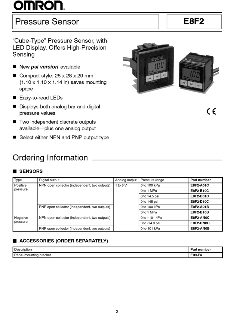
Pressure Sensor with an Easy-to-see
Digital Display
Two output modes ensure easy pressure control.
Compact model incorporates a self-diagnostic
function.
Washable (IP66).
SI-compatible models are available.
Ordering Information
Pressure
range
ON/OFF output
Linear output
Model
Positive pressure
0 to 98 kPa
NPN open collector
1 to 5 V
E8F-A01C
os e essu e
0 to 980 kPa
o e co ec o
o5
E8F-B10C
Negative pressure
0 to –101 kPa
E8F-AN0C
Positive pressure
0 to 1 kgf/cm
2E8F-01C
os e essu e
0 to 10 kgf/cm
2E8F-10C
Negative pressure
0 to –76 cmHg
E8F-CN0C
Application Examples
Checking
the wafer pick-up
Air leakage test on container pin holes
or cracks
E8F
E8F
Checking the chip pick-up
E8F
Checking the air press machine
pressure E8F
Checking the PCB and wafer pick-up
E8F
Output
Control of air chuck clamp pressure
E8F

E8F E8F
2
Specifications
Ratings
Item/Model E8F-A01C E8F-AN0C
(see note 1)
E8F-B10C E8F-01C E8F-CN0C
(see note 1)
E8F-10C
Supply voltage 12 to 24 VDC
±
10% with a ripple (p-p) of 10% max.
Current
consumption
30 mA max.
Pressure type
Gauge pressure
Permissible
pressure range
0 to 98 kPa
0 to –101 kPa
0 to 980 kPa
0 to 1 kgf/cm
2
(0 to 98 kPa)
0 to –76 cmHg
(0 to –101 kPa)
0 to 10 kgf/cm
2
(0 to 980 kPa)
Pressure setting
range
0 to 98 kPa
0 to –101 kPa
0 to 980 kPa
0 to 1 kgf/cm
2
(0 to 98 kPa)
0 to –76 cmHg
(0 to –101 kPa)
0 to 10 kgf/cm
2
(0 to 980 kPa)
W
ithstand pressure 490 kPa
2.0 MPa
5 kgf/cm2
(490 kPa)
20 kgf/cm
2
(2
MPa)
Applicable fluid
Non-corrosive gasses, inert gasses
Operating mode
(see note 2)
Hysteresis mode and wind mode
Repeat accuracy
(ON/OFF output) ±
1% FS max.
Accuracy
(linear output)
±
3% FS max.
Linearity
(linear output)
±
1% FS max.
Response time
(ON/OFF output)
6 ms max.
Linear output
1 to 5 V with output impedance of 1 k
Ω
and permissible resistive load of 500 k
Ω
min.
ON/OFF output NPN open collector (NO/NC)
Load current
100 mA max.
Output applied
voltage 30 VDC max.
Residual
voltage
1 V max. (with load current of 100 mA) or 0.4 V max. (with load current of 20 mA)
Error output
NPN open collector
Load current
50 mA max.
Output applied
voltage 30 VDC max.
Residual
voltage
1 V max. (with load current of 50 mA) or 0.4 V max. (with load current of 20 mA)
Power-ON reset time
200 ms max.
Display (see note 2)
21/2
-digit LCD
Red indicator ON with output transistor turned ON
Green indicator ON in normal operation (OFF at the time of malfunctioning or error detection)
Display accuracy
±
3% FS
±
1 digit max.
Circuit protection
Reversed connection and load short-circuiting
Ambient
temperature Operating: 0°
C to 50
°
C (with no icing)
Storage: –10°
C to 60
°C
Ambient humidity
35% to 85% (with no condensation)
Accessories
(provided)
Mounting brackets (horizontal bracket, vertical bracket, and two mounting screws) and operation manual

E8F E8F
3
Note: 1.
Negative-pressure model
2. Refer
to the following for the operation modes
available
at
the time of initial settings.
Hysteresis Mode
Pressure valve
OFF set value ON set value
Output 0.98Mpa
98 kPa
–101 kPa
10
kgf/cm
2
1kgf/cm2
–76cmHg
In the above, the ON point is set larger than the OFF
point.
Wind
Mode
Pressure valve
ON set value OFF set value
Output 0.98Mpa
98 kPa
–101 kPa
10
kgf/cm
2
1kgf/cm2
–76cmHg
In the above, the ON point is set smaller than the OFF
point.
3. The 21/2-digit display refers to a display in which the
third
digit displays only 0 or 1.
0 or 1
0 to 9 0 to 9
Third digit Second digit First digit
Characteristics
Voltage
influence
±
1.5% FS max.
T
emperature influence
±
3% FS max.
Degree of protection
IEC IP66
Dielectric strength
1,000 V
AC for 1 min
Insulation resistance
100 M
Ω
min. (at 500 VDC) between current carry parts and case
V
ibration resistance
Destruction: 10 to 500 Hz, 1.5-mm double amplitude or 100 m/s
2
(approx. 10G) for 2 hours
each in X, Y
, and Z directions
Shock resistance
Destruction: 500 m/s
2
(approx. 50G) 2 times each in X, Y
, and Z directions.
Pressure port R(PT) 1/8 taper screw and M5 x P0.8 female screw for zinc die-cast pressure port
Cord
2-m-long UL-approved cord
Weight
60 g (excluding cord)

E8F E8F
4
Engineering Data
Temperature vs. Linear Output Current
Fluctuation (Typical)
E8F-01C
Temperature vs. Operating Pressure
(Typical)
E8F-01C
Linear output fluctuation (% FS)
Temperature
(
°C)
Operation pressure fluctuation (% FS)
T
emperature (
°C)
Pressure vs. Linear Output (Typical)
E8F-01C Linearity (Typical)
E8F-01C
Linear output voltage (V)
Pressure (kgf/cm2)
Linearity deviation %FS)
Pressure (kgf/cm2)
Nomenclature
LCD display
(21/2digit display)
DOWN Key
UP Key
Green indicator Normal operation: ON
Detection of error or malfunctioning: OFF
Load short-circuiting or overcurrent: Flashing
Red indicator: Lit when the ON/OFF output transistor turns ON.
MODE Key: Used for the selection of measurement or setting mode.
ZERO Key: Used for zero-point adjustment.

E8F E8F
5
Operation
Output Circuit
RUN
indicator
(green)
OUT
indicator
(red)
Pressure
Sensor
main
circuit
Brown
Load
Orange
(error)
White (ON/OFF)
Black
Linear
output Load
Load
Blue
12 to 24 V
1 to 5 V
0 V
50 mA
max.
100 mA max.
Output Timing Charts
Normally
Open Output in Hysteresis Mode
Pressure
ON point
Output (see note) ON
OFF
OUT indicator (red)
RUN indicator (green)
ON
OFF
ON
OFF
Pressure
ON point
OFF point OFF point
Output (see note) ON
OFF
OUT indicator (red)
RUN indicator (green)
ON
OFF
ON
OFF
Normally
Closed Output in Hysteresis Mode
OFF point: 3 digits
ON point: 3 digits
OFF point: 3 digits
ON point: 3 digits
Note:
In the above examples, the ON- and OFF-delay timers are both set to 0 ms.
Normally Open Output in W
ind Mode
Pressure
ON point
Output (see note) ON
OFF
OUT indicator (red)
RUN indicator (green)
ON
OFF
ON
OFF
Pressure
ON point
OFF point OFF point
Output (see note)
ON
OFF
OUT indicator (red)
RUN indicator (green)
ON
OFF
ON
OFF
Normally
Closed Output in W
ind Mode

E8F E8F
6
Pressure Setting Method
(The
decimal point will not be displayed under the setting mode.)
Press the MODE Key
ON point setting
Press the MODE Key
OFF point setting
Press the MODE Key
ON-delay setting
Press the MODE Key
OFF-delay setting
Press the MODE Key
Normally open (NO) or nor
-
mally closed (NC) setting
Press the MODE Key
Buzzer setting
Press the MODE Key
(1)
(2)
(3)
(4)
(6)
(5)
LCD indication
ON 80
The LCD flashes. The dis
-
play changes between 0 and
the rated value by pressing
the Up or Down Key
.
LCD indication
OFF 30
LCD indication
ON d2
LCD indication
OFF d6
LCD indication
nc
LCD indication
b4
The LCD flashes. The dis
-
play changes between 0 and
the rated value by pressing
the Up or Down Key
.
The LCD flashes. The display
changes between d0 and d9
(i.e., 0 and 90 ms) by press
-
ing the Up or Down Key
.
The LCD flashes. The display
changes between d0 and d9
(i.e., 0 and 90 ms) by press
-
ing the Up or Down Key
.
The LCD flashes. The display
changes between NO and
NC by pressing the Up or
Down Key.
The LCD flashes. The display
changes between b0 and b5
by pressing the Up or Down
Key.
Setting completed. (proceeds to measurement mode)
Set values are stored in the EEPROM and not lost when
the E8F is turned OFF. If the Up Key is pressed in mea
-
surement mode, the set ON point will be displayed for
two seconds. If the Down Key is pressed instead, the set
OFF point will be displayed for two seconds.
(1) (2) ON/OFF Point Settings
ON point value > OFF point value: The E8F will be in hysteresis
mode.
ON
point value < OFF point value: The E8F will be in wind mode.
ON point = OFF point: No ON/OFF operation is possible.
Note: The
ON and OFF points
are both set to 30 before shipping.
Hysteresis
Mode
W
ind Mode
Pressure value
OFF set value ON set value
Pressure
value
OFF set valueON set value
Output
Output
*See note. *See note.
Note: Allowable
pressure varies with the model.
(3), (4) ON- and OFF-delay T
imer Settings
It
is possible to set ON- or OFF-delay timer within a range of 0
and
90 ms
in 10-ms increments. Set the timer to 0
ms if the timer function
is
not required.
Note:
The timer is set to 0 ms before shipping.
ON-delay
Delay
Sensing point
Output
Output
Delay
Sensing point
OFF-delay
(5)
Normally Open (NO) and Normally Closed (NC) Settings
Note:
The E8F is set to NO before shipping.
Hysteresis Mode
Pressure
ON point
OFF point
ON
OFF
ON
OFF
Output transistor
NO output
NC output
Wind
Mode
Pressure
ON point: 3 digits
OFF point: 3 digits
ON
OFF
ON
OFF
Output transistor
NO output
NC output
ON point
OFF point

E8F E8F
7
(6) Buzzer Mode Settings
Set the buzzer mode to 0 if the buzzer function is not required.
Note:
The mode is set to 3 before shipping.
Set value
Contents
0The buzzer is always OFF.
1
The buzzer is ON when the ON/OFF output
transistor is ON.
2
The buzzer is ON when an error is
detected.
3
The buzzer is ON when the Up or Down
Key is pressed when setting the values.
4
The functions of set values 1 and 3.
5
The functions of set values 2 and 3.
Error Indication
LCD Meaning Remedy
E1 The
ON/OFF output and error output transistor have excessive current.
Change the load to a proper one.
E2
No zero point adjustment is possible when the ZERO Key is pressed
because pressure is imposed on the pressure port.
Eliminate the pressure imposed on the pressure
port.
E3 Excessive pressure is imposed on the pressure port.
Reduce the pressure to the rated value or less.
E4 Reversed pressure is imposed.
Do not impose reversed pressure.
E5
The Sensor has a failure.
Contact your OMRON representatives.
E6
The voltage imposed on the Sensor is not within the rated value.
Impose the voltage within the rated value.
Note: 1. If
the load is short-circuited or excessive current flows to the load, the green indicator will flash and the ON/OFF output and error
output
will be turned OFF
.
2. If
there is an error other than a load short-circuit or excessive current error (i.e., E2 to E6), the green indicator will be turned OFF and
the
error output transistor will be turned ON. Therefore, nullify the ON/OFF output at the time of error detection.
Zero Point Adjustment
Usually, no zero point adjustment is necessary. If the zero point
should
shift due to secular changes (i.e., a value other than 00 is dis
-
played with no pressure imposed), press the ZERO Key for zero
point
adjustment.
Perform zero point adjustment with no pressure imposed.
ON/OFF Set Value Check on E8F in Operation
Press
the Up Key to check the ON set value.
Press the Down Key to check the OFF set value.
Mounting
The zinc die-cast
pressure leading part incorporates an R(PT) 1/8
taper
screw and M5 x P0.8 female screw
. The taper screw must be
used
in combination with an Rc(PT) 1/8 female taper screw
.
Apply sealing tape around the taper screw so that there will be no
pressure
leakage. Make sure that the tightening torque of the taper
screw
is 9.8 N
S
m (100 kgf
Scm) or less.
Make sure that the tightening torque of the M5 female screw is
2.3 N
S
m (23 kgf
Scm) or less.
When
tightening the male screw
, apply a 12-mm wrench to the hex
-
agonal
portion of the pressure port. Do not tighten the male screw
while holding the plastic case.
When
attaching the mounting bracket to the E8F
, make sure that the
tightening torque applied to the M2.5 screw is 0.29 N
S
m (3 kgf
S
cm)
or less.
Hexagonal portion
E8F E8F
8
Dimensions
Note: All
units are in millimeters unless otherwise indicated.
E8F
Wiring cord
Atmosphere inlet (*)
M5 screw (depth: 6)
R(PT) 1/8 zinc die-cast
1-dia. hole
Two, M2.5 x P0.45
Wiring cord
3 dia.
(*)
Mounting Bracket
Mounting
Dimensions
Material: SPCC uni-chrome plating (t=1.2)
Two, 3.5 dia.
Two, 3.5 dia.
Two, 3.5 dia.
20.5

E8F E8F
9
Precautions
Correct Use
Available Gases:
No corrosive or flammable gas can be used.
Filter
the gas with an appropriate air filter so that the applied gas will
be
free of moisture or oil.
Make sure that the pressure applied is within the rated range.
If
the silicone diaphragm is damaged, the E8F will not operate prop
-
erly.
Do not insert a screwdriver or steel wire into the interior of the
pressure-sensitive
parts through the pressure leading part.
The
E8F has a display error of
±
3% FS
±
1 digit at the time of ON or
OFF point setting at room temperature. If a
highly precise pressure
setting
is required, use a manometer
.
Nullify the ON/OFF output at the time of error detection.
If
the use of the E8F requires the
IP66 enclosure rating (e.g., wash
-
ing the E8F with water), be sure to connect a standard silicone tube
to
the atmosphere inlet. The silicone tube must have
a 2-mm inner
diameter
and 4-mm outer diameter
.
Reset Time:
The E8F is ready to operate within 200 ms after the E8F is turned
ON.
Make sure that the Sensor is free from ultrasonic vibration when
mounting
the E8F
.
Others:
If
no linear or error output is used, cut of
f the black and orange lead
wires
and apply insulation tape to the lead wires so that they will not
come
in contact with any other terminal.

E8F E8F
10

E8F E8F
11

E8F E8F
12
OMRON Corporation
Industrial Sensors Division
Sensing Devices and Components Division H.Q.
28th Fl., Crystal T
ower Bldg.
1-2-27, Shiromi, Chuo-ku,
Osaka 540-6028 Japan
Phone: (81)6-949-6012 Fax: (81)6-949-6021
ALL DIMENSIONS SHOWN ARE IN MILLIMETERS.
To
convert millimeters into inches, multiply by 0.03937. T
o convert grams into ounces, multiply by 0.03527.
Cat. No. D070-E1-1 In the interest of product improvement, specifications are subject to change without notice.
Printed
in Japan
0498-1M (0498)
a
This manual suits for next models
6
Table of contents
Other Omron Accessories manuals

Omron
Omron ZS-HLDS2T User manual

Omron
Omron Z510 User manual

Omron
Omron SYSMAC C200H User manual

Omron
Omron E2C-CR5B User manual

Omron
Omron fh series Instructions for use

Omron
Omron E3T - User manual

Omron
Omron B5WC User manual

Omron
Omron FHV7H-C004-H19-MC User guide

Omron
Omron F3S-TGR-CL_B User manual

Omron
Omron F10 User manual

Omron
Omron E3S-CR62 - User manual

Omron
Omron E3X-MDA11 User manual

Omron
Omron ZFX-C10 COMMUNICATION User manual

Omron
Omron E3Z-H User manual

Omron
Omron TL User manual

Omron
Omron E3X-HD0 User manual

Omron
Omron E2C-EDA Series User manual

Omron
Omron E3FZ-B User manual

Omron
Omron ZS-HLDS60 User manual

Omron
Omron E3ZM-V61 User manual