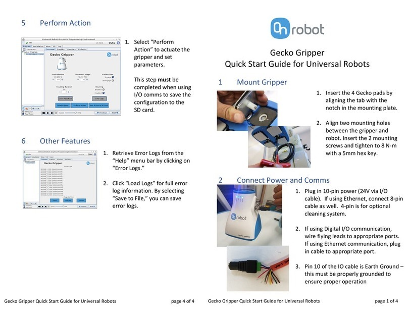
OnRobot Gecko SP1 User manual

USER MANUAL
FOR UR ROBOTS
v1.4.1
Original Instructions

Contents
1. Introduction.................................................................................................................................... 4
1.1. Important Safety Notice....................................................................................................................4
1.2. Scope of the Manual........................................................................................................................ 4
1.2.1. Gecko SP1/3/5.........................................................................................................................4
1.3. Copyright............................................................................................................................................. 4
2. Safety..............................................................................................................................................5
2.1. Intended Use......................................................................................................................................5
2.2. General Safety Instructions........................................................................................................... 5
2.3. Risk Assessment.............................................................................................................................. 6
2.4. Environmental Safety.......................................................................................................................7
3. HW Installation.............................................................................................................................. 8
3.1. Overview..............................................................................................................................................8
3.2. Robot Mount...................................................................................................................................... 8
3.2.1. Optional - Angle Bracket.....................................................................................................8
3.2.2. Quick Changer Mounting...................................................................................................9
3.2.2.1. Quick Changer - Robot Side.................................................................................. 9
3.2.2.2. Gecko SP1/3/5.......................................................................................................... 9
3.2.3. Tools........................................................................................................................................ 9
3.2.3.1. Gecko SP1/3/5............................................................................................................9
4. SW Installation..............................................................................................................................11
4.1. Gecko SP1/3/5 SW Installation.......................................................................................................11
5. Operation......................................................................................................................................12
5.1. Gecko SP Operation....................................................................................................................... 12
5.1.1. How the Gecko SP Works.................................................................................................. 12
5.1.2. TCP Setup..............................................................................................................................14
5.2. URScript Commands......................................................................................................................15
5.2.1. Gecko SP1/3/5...................................................................................................................... 15
5.2.1.1. Grip and Release...................................................................................................... 15
6. Hardware Specification.............................................................................................................. 16
6.1. Technical Sheets..............................................................................................................................16
6.1.1. Gecko SP1/3/5....................................................................................................................... 16
6.2. Mechanical Drawings................................................................................................................... 20
6.2.1. Adapter Plate.......................................................................................................................20
6.2.2. Angle Bracket......................................................................................................................21
6.2.3. Mountings............................................................................................................................22
6.2.3.1. Quick Changer - Robot Side................................................................................22
6.2.3.2. Quick Changer for I/O - Robot Side..................................................................23
6.2.4. Tools......................................................................................................................................23
2

6.2.4.1. Gecko SP1/3/5......................................................................................................... 23
6.3. COG, TCP.........................................................................................................................................24
6.3.1. Gecko SP1/3/5..................................................................................................................... 24
6.3.2. Angle Bracket..................................................................................................................... 24
7. Maintenance.................................................................................................................................27
7.1. Gecko SP1/3/5.................................................................................................................................. 27
7.1.1. Replacing the Gripper Pads...............................................................................................28
7.1.2. Replacing the Spring /Greasing the Bearing............................................................... 28
8. Troubleshooting..........................................................................................................................30
8.1. Tool Functions Are Not Available...............................................................................................30
8.2. Error During Operation.................................................................................................................30
9. Warranties.................................................................................................................................... 31
9.1. Patents................................................................................................................................................ 31
9.2. Product Warranty............................................................................................................................ 31
9.3. Disclaimer......................................................................................................................................... 31
10. Certifications..............................................................................................................................32
10.1. EMC...................................................................................................................................................33
10.2. Declaration of Incorporation......................................................................................................34
10.2.1. Gecko SP1/3/5....................................................................................................................34
3

1. Introduction
1.1. Important Safety Notice
DANGER:
You must read, understand, and follow all safety information in this manual, and
the robot manual and all associated equipment before initiating robot motion.
Failure to comply with safety information could result in death or serious injury.
1.2. Scope of the Manual
The manual covers the following OnRobot products and their components:
1.2.1. Gecko SP1/3/5
Tool Version
Gecko SP1/3/5 v1
1.3. Copyright
The information contained herein is property of OnRobot A/S and shall not be reproduced in
whole or in part without prior written approval of OnRobot A/S. The information herein is
subject to change without notice and should not be construed as a commitment by OnRobot
A/S. This manual is periodically reviewed and revised.
OnRobot A/S assumes no responsibility for any errors or omissions in this document.
Copyright © 2015–2020 by OnRobot A/S.
The OnRobot A/S logo is trademark of OnRobot A/S.
INTRODUCTION
4

2. Safety
The robot integrators are responsible for ensuring that the applicable safety laws and
regulations in the country concerned are observed and that any significant hazards in the
complete robot application are eliminated. This includes, but is not limited to:
•Performing a risk assessment for the complete robot system
•Interfacing other machines and additional safety devices if defined by the risk assessment
•Setting up the appropriate safety settings in the robot software
•Ensuring that the user will not modify any safety measures
•Validating that the total robot system is designed and installed correctly
•Specifying instructions for use
•Marking the robot installation with relevant signs and contact information of the integrator
•Collecting all documentation in a technical file; including the risk assessment and this
manual
2.1. Intended Use
OnRobot tools are intended to be used on collaborative robots and light industrial robots with
dierent payloads depending on the end-of-arm tooling specifications. OnRobot tools are
normally use in pick-and-place, palletizing, machine tending, assembly, quality testing and
inspection and surface finishing applications.
The end-of-arm tooling should only operate under conditions noted in 6.1. Technical Sheets
section.
Any use or application deviating from intended use is deemed to be impermissible misuse.
This includes, but is not limited to:
•Use in potentially explosive atmospheres
•Use in medical and life critical applications
•Use before performing a risk assessment
•Use outside the permissible operational conditions and specifications
•Use close to a human’s head, face and eye area
•Use as a climbing aid
2.2. General Safety Instructions
Generally, all national regulations, legislations and laws in the country of installation must be
observed. Integration and use of the product must be done in compliance with precautions in
this manual. Particular attention must be paid to the following warnings:
SAFETY
5

DANGER:
You must read, understand, and follow all safety information in this manual, and
the robot manual and all associated equipment before initiating robot motion.
Failure to comply with safety information could result in death or serious injury.
The information in this manual does not cover designing, installing, and
operating a complete robot application, nor does it cover other peripheral
equipment that can influence the safety of the complete system. The complete
system must be designed and installed in accordance with the safety
requirements set forth in the standards and regulations of the country where
the robot is installed.
Any safety information provided in this manual must not be construed as a
warranty, by OnRobot A/S, that the robot application will not cause injury or
damage, even if robot application complies with all safety instructions.
OnRobot A/S disclaims any and all liability if any of OnRobot tools tooling are
damaged, changed or modified in any way. OnRobot A/S cannot be held
responsible for any damages caused to any of OnRobot tools tooling, the
robot, or any other equipment due to programming errors or malfunctioning of
any of OnRobot tools.
WARNING:
OnRobot tools are not allowed to be exposed to condensing conditions when
power is on or when connected to a robot. If condensing conditions appear
during transport or storage, the product must be placed between 20 and 40
Celsius degrees for 24 hours before power is applied or before connected to a
robot.
It is recommended that OnRobot tools are integrated in compliance with the following guides
and standards:
•ISO 10218-2
•ISO 12100
•ISO/TR 20218-1
•ISO/TS 15066
2.3. Risk Assessment
The robot integrator must perform a risk assessment on the complete robot application.
OnRobot tools are only components in a robot application and therefore they can be only
safely operated if the integrator has considered the safety aspects of the whole application.
OnRobot tools are designed with relatively smooth and round design with a limited amount of
sharp edges and pinch points
In collaborative applications, the trajectory of the robot can play a significant safety role. The
integrator must consider the angle of contact with a human body, e.g. orientate OnRobot tools
and workpieces so that the contact surface in the direction of movement is as large as
possible. It is recommended that the tool connectors are pointed in the direction opposite to
the movement.
SAFETY
6

OnRobot A/S have identified the potential hazards listed below as significant hazards that
must be considered by the integrator:
•Objects flying from OnRobot tools due to loss of grip
•Objects falling down from OnRobot tools due to loss of grip
•Injuries due to collisions between humans and workpieces, OnRobot tools tooling, robot
or other obstacles
•Consequences due to loosen of bolts
•Consequences if OnRobot tools cable gets stuck to something
•Workpiece itself represents a hazard
2.4. Environmental Safety
OnRobot A/S products must be disposed of in accordance with the applicable national laws,
regulations and standards.
The product is produced with restricted use of hazardous substances to protect the
environment; as defined by the EU RoHS Directive 2011/65/EU. These substances include
mercury, cadmium, lead, chromium VI, polybrominated biphenyls and polybrominated
diphenyl ethers.
Observe national registration requirements for importers according to EU WEEE Directive
2012/19/EU.
SAFETY
7

3. HW Installation
3.1. Overview
For a successful installation the following steps will be required:
•Mount the components
•Setup the software
In the following sections, these installation steps will be described.
3.2. Robot Mount
1. Mount the robot-specific adapter (if applicable)
2. Mount any optional accessories
3. Mount the Quick Changer option
4. Mount the tool(s) (if applicable)
3.2.1. Optional - Angle Bracket
Angle Bracket
1. M6x10 screws (ISO14580 8.8)
2. Angle Bracket (ISO 9409-1-50-4-M6)
3. Dowel pin Ø6x10 (ISO2338 h8)
4. Adapter/Robot tool flange (ISO
9409-1-31.5-4-M5)
Use 10 Nm tightening torque.
NOTE:
If using the optional Angle Bracket, make sure to always adjust the TCP as
described in the 6.3.2. COG, TCP section. Otherwise some of the functionality
may not work properly.
NOTE:
With Angle Bracket the HEX-E/H QC and the Dual QC is not supported.
HW INSTALLATION
8

3.2.2. Quick Changer Mounting
3.2.2.1. Quick Changer - Robot Side
Quick Changer - Robot Side
1. M6x8mm (ISO14580 8.8)
2. Quick Changer (ISO 9409-1-50-4-
M6)
3. Dowel pin Ø6x10 (ISO2338 h8)
4. Adapter/ Robot tool flange (ISO
9409-1-50-4-M6)
Use 10 Nm tightening torque.
3.2.2.2. Gecko SP1/3/5
Tool QC-R v2 QC-R v2-4.5 A
Gecko SP1/3/5
3.2.3. Tools
3.2.3.1. Gecko SP1/3/5
First, install the single Gecko SP pad. The pad
simply screws into the Gecko SP base.
Then:
HW INSTALLATION
9

Step 1:
Move the tool close to the Quick Changer as
illustrated.
The hook mechanism (rod and hook tongue)
will keep the lower part locked once mounted.
Step 2:
Flip the tool until it is fully mated, and you hear
a clicking sound.
To unmount the tool, press the aluminum
button on the Quick Changer and repeat the
steps in the reverse order.
HW INSTALLATION
10

4. SW Installation
4.1. Gecko SP1/3/5 SW Installation
To use the Gecko SP1/3/5 gripper no URCap is required.
SW INSTALLATION
11

5. Operation
NOTE:
It is assumed that the Installation has finished successfully. If not, first do the
installation steps in the previous section.
5.1. Gecko SP Operation
The Gecko SP is a gripper that uses gecko-inspired adhesion to pick up flat objects without
an external power source such as an air system. There are three Gecko SP (Single Pad)
versions (SP 1, SP 3, SP 5) that have dierent maximum payload capacities (1 kg, 3 kg, and 5
kg, respectively).
In the following sections you will find instructions on:
•How the Gecko SP works.
•How to setup the right TCP for the peeling.
•How to Grip and Release with the Gecko SP.
5.1.1. How the Gecko SP Works
Gripper pick and place is entirely mechanical, and operation is controlled by the robot arm.
The Gecko Gripper attaches to flat and smooth object surfaces through the same mechanism
used by an actual gecko (van der Waals forces). This is accomplished through contact with
adhesive pads in a preload-hold-detach fashion.
The gripper creates adhesion by preloading the pads with a small force normal to the object’s
surface. This is achieved by pressing the gripper directly against the object’s surface.
The Gecko SP has a preload indicator.
By compressing the internal spring, a
maximum deflection of 4 mm can be achieved,
which results the maximum allowed preload
(for example 46N for a Gecko SP5).
OPERATION
12

When teaching the pickup position, the gecko
pad needs to be aligned on the workpiece
surface without compressing the spring. The
MIN sign of the preload indicator can be used
for checking.
To pick up a workpiece the robot needs to be
moved down a maximum of 4 mm to apply the
required preload.
(When fragile object needs to be handled, less
then 4mm downward movement can be made
for smaller preload force.)
Now the workpiece is gripped so it can be
lifted.
For putting down the workpiece, it must be
placed on its target place without pushing in
the spring. Again, the MIN mark can be used
to setup the correct position.
OPERATION
13

To peel o the Gecko SP pad from the
workpiece, the tool needs to be turned about
10 degrees around a set point on the pad’s
outer diameter while the object rests on a sti
surface that resists the rotation.
Therefore, it is very important to set the right
TCP (Tool Center Point) before the peeling
motion.
The part is released so the Gecko SP can be
moved away.
NOTE:
It is also possible for users to craft their own custom fixture to assist in peeling
o an object if the above method is not desirable. For example, the Gecko SP
could grip a panel and then visit a forked tool to slide between, move up and
release the object. The fixture design is completely at the user’s discretion.
5.1.2. TCP Setup
As highlighted in the previous section, it is very important to set the right TCP before the
peeling.
The peeling function will require X or Y and Z direction oset parameter to be set correctly.
NOTE:
If a Dual Quick Changer is used, the TCP rotation parameters must also be
specified according to the used side (Primary or Secondary).
Go to the TCP settings and add a new TCP and call it TCP_Gecko_SP.
There are three types of circular pads with the following diameters: 35, 60 and 75 mm.
When you program the peel o motion for the gripper, it is simpler to rotate it around a point
on the edge of the pad, therefore you should enter the half of the mounted pad size either in
the X or the Y coordinate field.
You can use any directions, so it can be positive or negative.
OPERATION
14

5.2. URScript Commands
URScript commands can be used alongside other scripts.
5.2.1. Gecko SP1/3/5
5.2.1.1. Grip and Release
An example file is provided on the USB stick that demonstrates how to grip and release, with
the help of the previously set TCP.
OPERATION
15

6. Hardware Specification
6.1. Technical Sheets
6.1.1. Gecko SP1/3/5
General Properties SP1 SP3 SP5 Unit
Maximum Payload 1
2.2
3
6.6
5
11
[kg]
[lb]
Preload
Minimum 3 8 12 [N]
Medium 7 20 29 [N]
Maximum 11 32 46 [N]
Detachment time 100-1000 (dependent on robot speed) [ms]
Holds workpiece on power loss? Yes, for days if well centered
IP Classification IP42
Dimensions (HxW) 69 x 71
2.7 x 2.8
[mm]
[inch]
Weight 0.267
0.587
0.297
0.653
0.318
0.7
[kg]
[lb]
Pads general properties Unit
Material Proprietary silicone blend
Wear properties Depends on surface roughness
Change-out interval ~200.000 [cycles]
Cleaning systems 1) OnRobot cleaning station
2) Silicone roller
3) Isopropyl Alcohol and lint-free cloth
Cleaning interval variable
Recovery 100%
Conditions Minimum Optimal Maximum Unit
Operating temperature 0
32
-
-
50
122
[°C]
[°F]
Storage temperature -30
-22
-
-
150
302
[°C]
[°F]
Surface Characteristics Matte finish Highly polished N/A Note: Smoother surfaces
require less preload force
for a desired payload force.
Spring lifetime* 1000000+ - - [cycles]
* Replacement information in the Maintenance section.
HARDWARE SPECIFICATION
16

How to Pick a Part Using the Gecko Gripper SP
Grip
Position Contact & Preload Lift
How to Release a Part
Method 1 – Robot Peeling Movement:
Release
Place Tilt to Release
Method 2 – Fixturing:
It is also possible for users to craft their own custom fixture to assist in peeling o an object if
the above method is not desirable. For example, the Gecko SP1/3/5 could grip a panel and
then visit a forked tool to slide between, move up and release the object. The fixture design is
completely at the user’s discretion.
Usage Notes
Because of the Gecko Gripper SP’s unique mechanism of action, it is important to understand
the following key operating principles to use the gripper correctly and to achieve optimal
gripper performance. This is VERY important.
•Surface Roughness Aects Gripping
The Gecko Gripper works best with highly polished surfaces that allow for maximal contact
between the adhesive pads and the substrate surface. As the surface becomes less
smooth, more preload force is required to grip substrates. Matte surfaces should be
considered the maximal surface roughness limit which the gripper is able to grip.
•Environmental Conditions Aect Gripping
The adhesive pads use van der Waals forces to attach to a substrate. If there is dust or
debris on the substrate surface, the pads will interact with these particles instead. Dusty,
HARDWARE SPECIFICATION
17

greasy, oily, or wet substrates will not adhere to the Gecko Gripper SP. The Gripper works
best with clean, smooth, and dry surfaces.
•Preload Force Determines Maximum Payload Force
The adhesion force is also dependent on the amount of preload force applied to the
surface. This preload force also depends on the surface smoothness or roughness.
Payload force is also saturable at some preload force specific to the material and
operating conditions; here maximal preload is applied.
•Reconcile Gripper Function with Robot Collision Detection or Other Safety Systems
When using the Gecko Gripper with a robot in position control, care must be taken during
the gripping phase of the object as to not trip o the robot’s collision detection system.
The most force of the gripper is dependent on pad size. Approximate maximum force
values for the SP gripper series are as follows: SP1 = 15N; SP2 = 40N; SP3 = 60N. Based
upon your robot type and object, it may be necessary to adjust the robot’s collaborative or
collision settings to preclude tripping o the robot upon contact.
•Pick Location and Object Moments Can Overcome Gripping Force
Gripper adhesion specifications assume that the center of gravity of the object is centered
on the gripper pad. If the center of gravity of the object is not centered on the pad or
moments are applied to the object, robot-object movement can decrease the adhesion
force of the gripper causing it to drop the objects.
•Pads will Wear Out
Over time, the gecko pads will wear and require replacement. There is no deterministic
way to determine how worn the pads are, so the user must be mindful of the pad change-
out interval. This will depend on the environment in which the pads are used.
Eectiveness on Dierent Materials
There are several factors that aect the gecko gripper’s ability to handle items: the micro
scale roughness of the surface (average roughness), the macro scale peaks and valleys on
the surface (spatial frequency of peaks – also waviness), also the orientation of these features
(lay – or the way it was finished, e.g. lapped, ground, Blanchard, etc.) and stiness of the
material. If the material is too soft, the gecko adhesive will not be able to force itself against
the material to grip. To make this easier to interpret, we have included the below table that
shows texture roughness and stiness on the left (scales of 1, 5 and 10 – the highest) versus
the payload of the Gecko SP1, SP3 and SP5. Green indicates that it is possible to pick this
object, yellow is questionable and red does not result in a pick. The scale is relative and semi-
arbitrary, meant to act as a general guide. More scientific information can be found in the
Gecko SP user guide.
Stiness Roughness Example of material / substrate Gecko SP-1
Payload [kg]
0.02 0.05 0.1 0.25 0.5 1
1 1 Loose Mylar
5 1 Transparency sheet
10 1 Polished mirror-like steel, metal,
solar panel
HARDWARE SPECIFICATION
18

Stiness Roughness Example of material / substrate Gecko SP-1
1 5 Cling film, ziploc bags
5 5 Glossy carboard (cereal box)
10 5 Printed circuit board
1 10 Laminating plastic / film
5 10 Corrugated cardboard
10 10 Sandblasted aluminum
Stiness Roughness Example of material / substrate Gecko SP-3
Payload [kg]
0.1 0.2 0.3 0.75 1.5 3
1 1 Loose Mylar
5 1 Transparency sheet
10 1 Polished mirror-like steel, metal,
solar panel
1 5 Cling film, ziploc bags
5 5 Glossy carboard (cereal box)
10 5 Printed circuit board
1 10 Laminating plastic / film
5 10 Corrugated cardboard
10 10 Sandblasted aluminum
Stiness Roughness Example of material / substrate Gecko SP-5
Payload [kg]
0.1 0.25 0.5 1.0 2.5 5
1 1 Loose Mylar
5 1 Transparency sheet
10 1 Polished mirror-like steel, metal,
solar panel
1 5 Cling film, ziploc bags
5 5 Glossy carboard (cereal box)
10 5 Printed circuit board
1 10 Laminating plastic / film
5 10 Corrugated cardboard
10 10 Sandblasted aluminum
HARDWARE SPECIFICATION
19

NOTE:
These tables are to be utilized as a guide to better understand the payload
capacity and substrate type for the Gecko Gripper SP1/3/5.
The criteria for stiness and roughness is a basic scale from 1-10, here are the benchmarks
used to determine the values.
Stiness Description Example
1 Flexible Fabric
5Semi-flexible Cardboard
10 Sti Metal
Roughness Description Example RMS Value
1 Polished/Smooth Polished Metal 0.1 micron
5 Textured Carboard 7 microns
10 Rough Sandblasted Metal 28 microns
6.2. Mechanical Drawings
6.2.1. Adapter Plate
No adapter plate is required.
HARDWARE SPECIFICATION
20
This manual suits for next models
2
Table of contents
Other OnRobot Robotics manuals

OnRobot
OnRobot UR CB3 Series User manual

OnRobot
OnRobot 3FG15 User manual

OnRobot
OnRobot VG10 User manual

OnRobot
OnRobot 2FGP20 User manual

OnRobot
OnRobot DOOSAN Gecko Gripper User manual

OnRobot
OnRobot HEX-E QC User manual

OnRobot
OnRobot RG2 User manual

OnRobot
OnRobot 3FG15 User manual

OnRobot
OnRobot RG2-FT User manual

OnRobot
OnRobot RG2-FT User manual
Popular Robotics manuals by other brands

Hasbro
Hasbro Marvel Avengers Infinity War Legends Infinity... quick start guide

Butterfly
Butterfly Amicus 3000 Plus user manual

ROBOTIQ
ROBOTIQ 2F-85 quick start guide

Pudu
Pudu BelleBot BL100 user manual

Mitsubishi
Mitsubishi MELFA RV-6S Series instruction manual

ROBOTIQ
ROBOTIQ 2-Finger 85 instruction manual