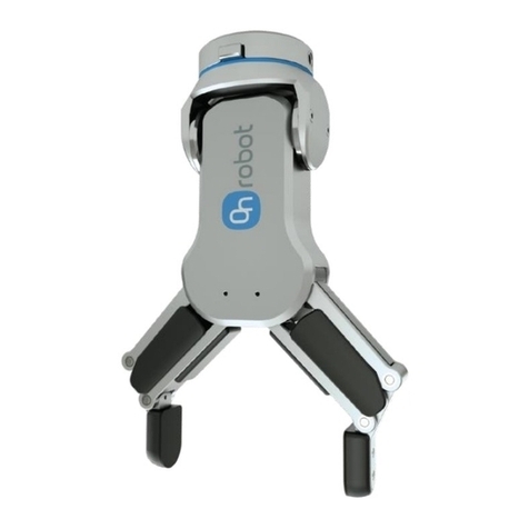
OnRobot UR CB3 Series User manual

USER MANUAL
FOR UR ROBOTS
v1.4.1
Original Instructions

Contents
1. Introduction.................................................................................................................................... 5
1.1. Important Safety Notice....................................................................................................................5
1.2. Scope of the Manual........................................................................................................................ 5
1.2.1. RG2-FT......................................................................................................................................5
1.2.2. Software and Firmware....................................................................................................... 5
1.2.2.1. URCap Software.........................................................................................................5
1.2.2.2. Compute Box............................................................................................................. 5
1.3. Naming Convention..........................................................................................................................6
1.3.1. Compute Box/Eye Box..........................................................................................................6
1.4. Copyright.............................................................................................................................................6
2. Safety.............................................................................................................................................. 7
2.1. Intended Use...................................................................................................................................... 7
2.2. General Safety Instructions............................................................................................................7
2.3. Risk Assessment...............................................................................................................................8
2.4. Environmental Safety...................................................................................................................... 9
3. Operation Mode(s)...................................................................................................................... 10
3.1. Operation via Compute Box......................................................................................................... 10
4. HW Installation............................................................................................................................. 11
4.1. Overview............................................................................................................................................. 11
4.2. Robot Mount......................................................................................................................................11
4.2.1. Optional - Angle Bracket.................................................................................................... 11
4.2.2. Quick Changer Mounting................................................................................................. 12
4.2.2.1. Quick Changer - Robot Side.................................................................................12
4.2.2.2. RG2-FT...................................................................................................................... 12
4.2.3. Tools.......................................................................................................................................12
4.2.3.1. RG2-FT....................................................................................................................... 12
4.3. Compute Box Mount...................................................................................................................... 13
4.3.1. Optional - Clip-on Bracket................................................................................................. 13
4.4. Wiring via Compute Box................................................................................................................13
4.4.1. Tool Data Cable....................................................................................................................14
4.4.1.1. RG2-FT........................................................................................................................ 14
4.4.2. Ethernet Cable.................................................................................................................... 15
4.4.3. Power Supply: Compute Box...........................................................................................15
4.4.3.1. RG2-FT....................................................................................................................... 16
5. SW Installation............................................................................................................................. 17
5.1. Robot Software Setup.....................................................................................................................17
5.1.1. Install URCap..........................................................................................................................17
5.1.2. Uninstall Software............................................................................................................... 18
2

5.1.3. URCap Setup........................................................................................................................ 19
5.1.3.1. Load Multiple Devices.............................................................................................19
5.1.3.2. Setup Tool Connector............................................................................................ 21
5.1.3.3. Device Info............................................................................................................... 22
5.1.3.4. RG2-FT...................................................................................................................... 23
6. Operation.....................................................................................................................................28
6.1. URCap Commands.........................................................................................................................28
6.1.1. RG2-FT................................................................................................................................... 28
6.1.1.1. RG Grip........................................................................................................................28
6.1.1.2. RG2-FT Insert Part...................................................................................................30
6.1.1.3. HEX-Force Control.................................................................................................. 33
6.1.1.4. HEX-Search...............................................................................................................35
6.1.1.5. HEX-Zero................................................................................................................... 37
6.1.1.6. OnWaypoint.............................................................................................................. 38
6.1.1.7. TCP.............................................................................................................................. 39
6.2. URCap Toolbar............................................................................................................................... 39
6.2.1. RG2-FT.................................................................................................................................. 42
6.3. URScript Commands.....................................................................................................................45
6.3.1. RG2-FT.................................................................................................................................. 45
6.4. TCP Configuration......................................................................................................................... 46
6.5. Feedback Variables...................................................................................................................... 50
6.5.1. RG2-FT.................................................................................................................................. 50
7. Additional Software Options..................................................................................................... 52
7.1. Compute Box/Eye Box................................................................................................................... 52
7.1.1. Interfaces................................................................................................................................52
7.1.2. Web Client.............................................................................................................................52
7.1.3. Web Client: Devices Menu................................................................................................54
7.1.3.1. RG2-FT........................................................................................................................55
7.1.4. Web Client: Configuration Menu..................................................................................... 57
7.1.5. Web Client: Update Menu.................................................................................................58
7.1.6. Web Client: Account Settings..........................................................................................60
8. Hardware Specification............................................................................................................. 64
8.1. Technical Sheets............................................................................................................................. 64
8.1.1. RG2-FT................................................................................................................................... 64
8.1.2. Compute Box.......................................................................................................................69
8.1.2.1. With 1.5A Wall Adapter (36W).............................................................................. 69
8.1.2.2. With 6.25A Wall Adapter (150W)........................................................................ 70
8.1.2.3. Compute Box I/O interface.................................................................................. 70
8.2. Mechanical Drawings.....................................................................................................................71
8.2.1. Adapter Plate........................................................................................................................ 71
8.2.2. Angle Bracket...................................................................................................................... 71
3
8.2.3. Mountings............................................................................................................................ 72
8.2.3.1. Quick Changer - Robot Side................................................................................72
8.2.3.2. Quick Changer for I/O - Robot Side..................................................................73
8.2.4. Tools...................................................................................................................................... 74
8.2.4.1. RG2-FT.......................................................................................................................74
8.2.4.2. Compute Box..........................................................................................................75
8.3. COG, TCP......................................................................................................................................... 75
8.3.1. RG2-FT...................................................................................................................................76
8.3.2. Angle Bracket..................................................................................................................... 76
9. Maintenance................................................................................................................................ 79
9.1. RG2-FT...............................................................................................................................................79
10. Troubleshooting........................................................................................................................ 80
10.1. URCap Operation..........................................................................................................................80
10.2. Tool Functions Are Not Available............................................................................................ 80
10.3. Error During Operation............................................................................................................... 80
11. Warranties................................................................................................................................... 81
11.1. Patents............................................................................................................................................... 81
11.2. Product Warranty............................................................................................................................81
11.3. Disclaimer.........................................................................................................................................81
12. Certifications..............................................................................................................................82
12.1. EMC...................................................................................................................................................83
12.2. Declaration of Incorporation..................................................................................................... 84
12.2.1. RG2-FT.................................................................................................................................84
4

1. Introduction
1.1. Important Safety Notice
DANGER:
You must read, understand, and follow all safety information in this manual, and
the robot manual and all associated equipment before initiating robot motion.
Failure to comply with safety information could result in death or serious injury.
1.2. Scope of the Manual
The manual covers the following OnRobot products and their components:
1.2.1. RG2-FT
Tool Version
RG2-FT v2
1.2.2. Software and Firmware
1.2.2.1. URCap Software
The manual covers the following software versions:
Software Version
URCap v5.4.4
1.2.2.2. Compute Box
The manual covers the following Compute Box software version:
Software Version
Compute Box v5.4.4
NOTE:
When the used Compute Box has lower software/firmware version, update the
Compute Box. For detailed instructions, see 7.1.5. Web Client: Update Menu.
INTRODUCTION
5

1.3. Naming Convention
1.3.1. Compute Box/Eye Box
Eye Box and Compute Box are used interchangeably.
1.4. Copyright
The information contained herein is property of OnRobot A/S and shall not be reproduced in
whole or in part without prior written approval of OnRobot A/S. The information herein is
subject to change without notice and should not be construed as a commitment by OnRobot
A/S. This manual is periodically reviewed and revised.
OnRobot A/S assumes no responsibility for any errors or omissions in this document.
Copyright © 2015–2020 by OnRobot A/S.
The OnRobot A/S logo is trademark of OnRobot A/S.
INTRODUCTION
6

2. Safety
The robot integrators are responsible for ensuring that the applicable safety laws and
regulations in the country concerned are observed and that any significant hazards in the
complete robot application are eliminated. This includes, but is not limited to:
•Performing a risk assessment for the complete robot system
•Interfacing other machines and additional safety devices if defined by the risk assessment
•Setting up the appropriate safety settings in the robot software
•Ensuring that the user will not modify any safety measures
•Validating that the total robot system is designed and installed correctly
•Specifying instructions for use
•Marking the robot installation with relevant signs and contact information of the integrator
•Collecting all documentation in a technical file; including the risk assessment and this
manual
2.1. Intended Use
OnRobot tools are intended to be used on collaborative robots and light industrial robots with
dierent payloads depending on the end-of-arm tooling specifications. OnRobot tools are
normally use in pick-and-place, palletizing, machine tending, assembly, quality testing and
inspection and surface finishing applications.
The end-of-arm tooling should only operate under conditions noted in 8.1. Technical Sheets
section.
Any use or application deviating from intended use is deemed to be impermissible misuse.
This includes, but is not limited to:
•Use in potentially explosive atmospheres
•Use in medical and life critical applications
•Use before performing a risk assessment
•Use outside the permissible operational conditions and specifications
•Use close to a human’s head, face and eye area
•Use as a climbing aid
2.2. General Safety Instructions
Generally, all national regulations, legislations and laws in the country of installation must be
observed. Integration and use of the product must be done in compliance with precautions in
this manual. Particular attention must be paid to the following warnings:
SAFETY
7

DANGER:
You must read, understand, and follow all safety information in this manual, and
the robot manual and all associated equipment before initiating robot motion.
Failure to comply with safety information could result in death or serious injury.
The information in this manual does not cover designing, installing, and
operating a complete robot application, nor does it cover other peripheral
equipment that can influence the safety of the complete system. The complete
system must be designed and installed in accordance with the safety
requirements set forth in the standards and regulations of the country where
the robot is installed.
Any safety information provided in this manual must not be construed as a
warranty, by OnRobot A/S, that the robot application will not cause injury or
damage, even if robot application complies with all safety instructions.
OnRobot A/S disclaims any and all liability if any of OnRobot tools tooling are
damaged, changed or modified in any way. OnRobot A/S cannot be held
responsible for any damages caused to any of OnRobot tools tooling, the
robot, or any other equipment due to programming errors or malfunctioning of
any of OnRobot tools.
WARNING:
OnRobot tools are not allowed to be exposed to condensing conditions when
power is on or when connected to a robot. If condensing conditions appear
during transport or storage, the product must be placed between 20 and 40
Celsius degrees for 24 hours before power is applied or before connected to a
robot.
It is recommended that OnRobot tools are integrated in compliance with the following guides
and standards:
•ISO 10218-2
•ISO 12100
•ISO/TR 20218-1
•ISO/TS 15066
2.3. Risk Assessment
The robot integrator must perform a risk assessment on the complete robot application.
OnRobot tools are only components in a robot application and therefore they can be only
safely operated if the integrator has considered the safety aspects of the whole application.
OnRobot tools are designed with relatively smooth and round design with a limited amount of
sharp edges and pinch points
In collaborative applications, the trajectory of the robot can play a significant safety role. The
integrator must consider the angle of contact with a human body, e.g. orientate OnRobot tools
and workpieces so that the contact surface in the direction of movement is as large as
possible. It is recommended that the tool connectors are pointed in the direction opposite to
the movement.
SAFETY
8

OnRobot A/S have identified the potential hazards listed below as significant hazards that
must be considered by the integrator:
•Objects flying from OnRobot tools due to loss of grip
•Objects falling down from OnRobot tools due to loss of grip
•Injuries due to collisions between humans and workpieces, OnRobot tools tooling, robot
or other obstacles
•Consequences due to loosen of bolts
•Consequences if OnRobot tools cable gets stuck to something
•Workpiece itself represents a hazard
2.4. Environmental Safety
OnRobot A/S products must be disposed of in accordance with the applicable national laws,
regulations and standards.
The product is produced with restricted use of hazardous substances to protect the
environment; as defined by the EU RoHS Directive 2011/65/EU. These substances include
mercury, cadmium, lead, chromium VI, polybrominated biphenyls and polybrominated
diphenyl ethers.
Observe national registration requirements for importers according to EU WEEE Directive
2012/19/EU.
SAFETY
9

3. Operation Mode(s)
This document covers installation and operation for both:
•UR CB3 series robot controllers
•and UR e-Series robot controllers.
Since the two controllers have similar installation and operation screens in these cases only
the e-Series screens are shown. Where the two requires dierent steps or screens it is
highlighted and referred as:
•CB3 series
•e-Series.
3.1. Operation via Compute Box
The product(s) could be used on both UR series via Compute Box, which works with all
products and product combinations. Diernet modes of operation require the same
installation/operation steps. Where the via Compute Box mode requires dierent steps, it is
highlighted and referred as via Compute Box.
OPERATION MODE(S)
10

4. HW Installation
4.1. Overview
For a successful installation the following steps will be required:
•Mount the components
•Setup the software
In the following sections, these installation steps will be described.
4.2. Robot Mount
1. Mount the robot-specific adapter (if applicable)
2. Mount any optional accessories
3. Mount the Quick Changer option
4. Mount the tool(s) (if applicable)
4.2.1. Optional - Angle Bracket
Angle Bracket
1. M6x10 screws (ISO14580 8.8)
2. Angle Bracket (ISO 9409-1-50-4-M6)
3. Dowel pin Ø6x10 (ISO2338 h8)
4. Adapter/Robot tool flange (ISO
9409-1-31.5-4-M5)
Use 10 Nm tightening torque.
NOTE:
If using the optional Angle Bracket, make sure to always adjust the TCP as
described in the 8.3.2. COG, TCP section. Otherwise some of the functionality
may not work properly.
NOTE:
With Angle Bracket the HEX-E/H QC and the Dual QC is not supported.
HW INSTALLATION
11

4.2.2. Quick Changer Mounting
4.2.2.1. Quick Changer - Robot Side
Quick Changer - Robot Side
1. M6x8mm (ISO14580 8.8)
2. Quick Changer (ISO 9409-1-50-4-
M6)
3. Dowel pin Ø6x10 (ISO2338 h8)
4. Adapter/ Robot tool flange (ISO
9409-1-50-4-M6)
Use 10 Nm tightening torque.
4.2.2.2. RG2-FT
Tool QC-R v2 QC-R v2-4.5 A
RG2-FT
4.2.3. Tools
4.2.3.1. RG2-FT
Step 1:
Move the tool close to the Quick Changer as
illustrated.
The hook mechanism (rod and hook tongue)
will keep the lower part locked once mounted.
Step 2:
Flip the tool until it is fully mated, and you hear
a clicking sound.
To unmount the tool, press the aluminum
button on the Quick Changer and repeat the
steps in the reverse order.
HW INSTALLATION
12

To change the relative angle of the gripper to
the Quick Changer:
•first remove the four M4x6 screws
•tilt the gripper between -60° and 90°
•then put the four M4x6 screws back and
use 3.5 Nm tightening torque to fix it.
WARNING:
Never use the device while any of the four M4x6 screws are removed.
4.3. Compute Box Mount
4.3.1. Optional - Clip-on Bracket
Optionally, fix the Compute Box to a surface using the provided Clip-on Brackets ( included
only from 17th December 2020).
Do the following on both sides of the Compute Box:
1. Hook the Clip-on Bracket to the rail on the side of the Compute Box and then flip it down.
2. Fasten the Clip-on Bracket with the plastic srew.
4.4. Wiring via Compute Box
DANGER:
Use only original OnRobot tool data cables.
Connect the following cables to wire the system:
•Tool data cable between the tool(s) and the Compute Box
•Ethernet cable between the robot controller and the Compute Box
•Power supply of the Compute Box
HW INSTALLATION
13

NOTE:
For the Quick Changer - Robot Side no cable is needed to be connected.
4.4.1. Tool Data Cable
4.4.1.1. RG2-FT
First connect the data cable to the tool.
For RG2-FT the Quick Changer tool data
connector cannot be used. Instead use the
marked M8-4pin connector.
Then route the Tool data cable to the Compute Box (CB) and use the supplied Velcro tape
(black) to fix it.
NOTE:
Make sure that during the routing some extra length is used at the joints so
that cable is not pulled when the robot moves.
Also make sure that the cable bending radius is minimum 40mm (for the HEX-
E/H QC it is 70mm).
Finally, connect the other end of the Tool data cable to the Compute Box's DEVICES
connector.
HW INSTALLATION
14

CAUTION:
Quick Changer and Dual Quick
Changer can only be used to
power OnRobot tools.
4.4.2. Ethernet Cable
Connect one end of the supplied Ethernet (UTP) cable to the robot controller's Ethernet (LAN)
port.
NOTE:
If the robot controller's Ethernet port is in use, use a standard 4-port Ethernet
switch to be able to use two network devices at the same time.
Connect the other end of the supplied cable to the Compute Box's ETHERNET connector.
CAUTION:
Use only shielded, maximum 3m long Ethernet cables.
WARNING:
Check and make sure that the Compute Box enclosure (metal) and the robot
controller enclosure (metal) are not connected (no galvanic connection
between the two).
4.4.3. Power Supply: Compute Box
Connect the supplied power supply to the Compute Box 24V connector.
HW INSTALLATION
15

NOTE:
To disconnect the power connector,
make sure to pull the connector housing
(where the arrows are shown) and not
the cable.
CAUTION:
Use only original OnRobot power
supplies.
Finally, power up the power supply that will power the Compute Box and the connected
Tool(s).
4.4.3.1. RG2-FT
Tool Power Supply 1.5 A Power Supply 5 A Power Supply 6.25 A
RG2-FT
HW INSTALLATION
16

5. SW Installation
5.1. Robot Software Setup
5.1.1. Install URCap
UR CB3 UR e-Series
NOTE:
The minimum UR PolyScope
version is 3.10. Please remove
all previous OnRobot URCap
version(s) before the
installation. The controller
version must be CB3.1.
For the HEX-E/H QC products
the 3.12 is not recommended.
NOTE:
The minimum UR PolyScope
version is 5.4. Please remove
all previous OnRobot URCap
version(s) before the
installation.
For the HEX-E/H QC products
the 5.6 is not recommended,
instead please use the 5.7.
1. Insert the OnRobot USB drive in the USB
slot on the right side of the Teach Pendant.
1. Insert the OnRobot USB drive in the USB
slot on the top right side of the Teach
Pendant.
2. Select the Setup Robot option from the
main menu, then the URCaps option. 2. Then tap on the menu (top right corner
of the screen), then from the System
section tap on the URCaps menu.
3. Tap on the +sign to browse for the
OnRobot URCap file. It can be found in the
usbdisk/UR/URCAP folder. Tap on
Open.
3. Tap on the + sign to browse for the
OnRobot URCap file. It can be found in the
usbdisk/UR/URCAP folder. Tap on
Open.
SW INSTALLATION
17

4. The system needs to be restarted for the
changes to take eect. Tap on the Restart
button and then wait for the system to be
restarted.
4. Then the system needs to be restarted for
the changes to take eect. Tap on the
Restart button and then wait for the system
to be restarted.
5. Initialize the robot. 5. Initialize the robot.
NOTE:
For more information on the
URCap installation please refer
to UR documentation.
5.1.2. Uninstall Software
UR CB3 UR e-Series
1. Select the Setup Robot option from the
main menu, then the URCaps option. 1. Tap on the menu (top right corner of the
screen), then from the System section tap
on the URCaps menu.
2. Select the OnRobot URCap file. 2. Select the OnRobot URCap file.
3. Tap on the - sign. 3. Tap on the - sign.
4. Then the system needs to be restarted for
the changes to take eect. Tap on the
Restart button and then wait for the system
to be restarted.
4. Then the system needs to be restarted for
the changes to take eect. Tap on the
Restart button and then wait for the system
to be restarted.
SW INSTALLATION
18

5. Initialize the robot. 5. Initialize the robot.
5.1.3. URCap Setup
UR CB3 UR e-Series
Select the Installation tab, then select
OnRobot Setup. The following screen is
shown:
Tap on the Installation tab in the top menu.
Then tap on the URCaps.
5.1.3.1. Load Multiple Devices
Device info
In the normal view of the panel, the available functions are shown below:
Dropdown menu to select a device-robot communication channel: Select whether you want
to discover the devices connected to the tool connector or to the compute box.
SW INSTALLATION
19

Use the reload button to find new available devices.
The automatically loads the selected devices to the UR environment, even if the device is
not connected to the robot. When you change between loaded devices, the robot does not
require a restart but you should press the reload button to refresh the detected devices.
WARNING:
When multiple devices are activated, you may experience slow URCap
operation. In this case, activate only the devices that you use. It is
recommended to activate up to two devices at the same time.
For each loaded device, the appropriate URCaps commands and Toolbar will be visible,
hence load only the devices that you will change frequently.
NOTE:
To use the newly discovered devices you might need to restart PolyScope. To
do that simply press the Restart now button. Remember to save it before, if
there are any unsaved changes in your program or settings.
NOTE:
After setting up the device the changes need to be saved to be part of the
current installation.
For the e-Series UR robots tap on the Save button (from the top menu and
use the Save Installation button .
For the CB3 UR robots use the Save button .
NOTE:
OnRobot products are checked after the robot is restarted and the saved
settings are restored while loading a program. That check could take up to 5
seconds via the Quick Changer for I/O. Therefore make sure to wait at least 5
seconds before you start your program. To make sure that the device is
connected check the Device info.
If the connected OnRobot product is changed, always go to the Device info to
check if the change was successful.
CAUTION:
After any error message is shown that is related to the connection to our
devices, please go to the Device info to make sure that the right settings (e.g.:
TCP) are used.
SW INSTALLATION
20
Other manuals for UR CB3 Series
1
This manual suits for next models
2
Table of contents
Other OnRobot Robotics manuals

OnRobot
OnRobot RG6 User manual

OnRobot
OnRobot 2FGP20 User manual

OnRobot
OnRobot 3FG15 User manual

OnRobot
OnRobot Gecko Gripper User manual

OnRobot
OnRobot RG2-FT User manual

OnRobot
OnRobot VGC10 User manual

OnRobot
OnRobot HEX-E QC User manual

OnRobot
OnRobot Gecko Gripper Product information sheet

OnRobot
OnRobot RG2 User manual

OnRobot
OnRobot VG10 User manual