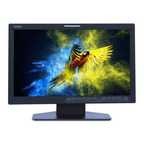
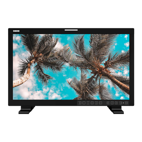
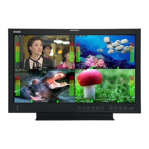
OSEE LCM215-E Series User manual

LCM156-E/LCM170-E/
LCM215-E/LCM230-E/
LCM240-E Series
LCD Monitor
User Manual


Product Information
Model:
LCM156-E/LCM170-E/LCM215-E/ LCM230-E/LCM240-E
Series LCD Monitor
Version:
V010101
Release Date:
November 11th, 2020
Company
OSEE TECHNOLOGY LTD.
Contact Information
OSEE TECHNOLOGY CO., LTD.
Address:
No.22 Building, No.68 zone, Beiqing Road, Haidian District,
Beijing, China
Post Code:
100094
Tel:
(+86) 010-62434168
Fax:
(+86) 010-62434169
Web:
http://www.osee-dig.com/
E-mail:

About this manual
Important
The following symbols are used in this manual:
The further information or know-how for described subjects above which
helps user to understand them better.
The safety matters or operations that user must pay attention to when
using this product.
Contents
The user manual applies to the following device types:
LCM156-E
LCM170-E
LCM215-E
LCM230-E
LCM240-E
The images and descriptions of LCM156-E are adopted as examples in the
following document. The basic features and functionalities for LCM156-E,
LCM170-E and LCM230-E are almost as the same, any of the different
specifications among the device types are elaborated.
Before reading the manual, please confirm the device type.

I
Contents
Contents ..........................................................................................................I
Chapter 1 Safety.............................................................................................1
Chapter 2 Unpack and Installation ...............................................................5
Chapter 3 Locations and Function of Parts and Control............................9
3.1 Front Panel ..........................................................................................9
3.1.1 Location of Control Buttons ..............................................................9
3.1.2 Function of Control Buttons..............................................................9
3.2 Rear Panel .........................................................................................13
3.3 Supported Signal Format .................................................................18
Chapter 4 Menu Operations........................................................................21
4.1 Main Menu..........................................................................................22
4.1.1 STATUS Menu ...............................................................................24
4.1.2 INPUT SELECT Menu....................................................................25
4.1.3 MARKER Menu ..............................................................................28
4.1.4 AUDIO Menu..................................................................................32
4.1.5 DISPLAY Menu ..............................................................................36
4.1.6 CLOSED CAPTION Menu..............................................................40
4.1.7 CONFIG Menu................................................................................42
4.1.8 LOOK PROFILE Menu ...................................................................49
4.1.9 FUNCTION KEY Menu...................................................................51
4.1.10 KEY INHIBIT Menu.......................................................................56
4.2 Menu Settings....................................................................................58
Chapter 5 Specifications.............................................................................61
5.1 Product detailed information ...........................................................61
5.2 Optional Accessories........................................................................63
5.3 Dimensions........................................................................................73


Safety
1
Chapter 1 Safety
FCC Caution:
Any Changes or modifications not expressly approved by the party responsible for
compliance could void the user's authority to operate the equipment.
This device complies with part 15 of the FCC Rules.
Operation is subject to the following two conditions: (1) This device may not cause
harmful interference, and (2) this device must accept any interference received,
including interference that may cause undesired operation.
Note: This equipment has been tested and found to comply with the limits for a Class
B digital device, pursuant to part 15 of the FCC Rules. These limits are designed to
provide reasonable protection against harmful interference in a residential installation.
This equipment generates uses and can radiate radio frequency energy and, if not
installed and used in accordance with the instructions, may cause harmful
interference to radio communications. However, there is no guarantee that
interference will not occur in a particular installation. If this equipment does cause
harmful interference to radio or television reception, which can be determined by
turning the equipment off and on, the user is encouraged to try to correct the
interference by one or more of the following measures:
Reorient or relocate the receiving antenna.
Increase the separation between the equipment and receiver.
Connect the equipment into an outlet on a circuit different from that to which the
receiver is connected.
Consult the dealer or an experienced radio/TV technician for help.

Safety
2
Warnings:
Read, keep and follow all of these instructions for your safety. Heed all warnings.
Device
Install in accordance with the manufacturer's instructions.
Do not beat with a hard object or scratch the LCD display.
Do not make the freeze picture displaying on the screen time too long,
otherwise, it will leave the afterimage on the screen.
If the brightness is adjusted to the minimum, then it might be hard to see the
display screen.
Refer all servicing to qualified service personnel. Servicing is required if any of
the following occurs:
The unit has been exposed to rain or moisture.
Liquid had been spilled or objects have fallen onto the unit.
The unit has been damaged in any way, such as when the power-supply
cord or plug is damaged.
The unit does not operate normally, or has been dropped.
Clean only with dry cloth.
Do not block any ventilation openings. Leave enough space around the unit
for ventilation.
Do not use this unit near water.
Do not use this unit near any heat sources such as radiators, heat registers,
stoves, or other apparatus (including amplifiers) that product heat.
A nameplate indicating operating voltage, etc., is located on the rear panel.
The socket-outlet shall be installed near the equipment and shall be easily
accessible.
To reduce the risk of fire or electric shock, do not expose the unit to rain or
moisture.
To avoid electrical shock, do not open the cabinet. Refer all servicing to
qualified service personnel.
If the product needs replacement parts, make sure that the service person use
replacement parts specified by the manufacture, or those with the same
characteristics and performance as the original parts. Use of unauthorized
parts can result in fire, electric shock and/or other damage.
The panel used in this produce is made of glass. Therefore, it can break when
it is dropped or applied with impact. Be careful not to be injured by broken
glass pieces.
3
Specifications are subject to change without notice.
Do not use attachments or accessories not recommended by the manufacture.
Use of inadequate attachments may result in serious accidents.
Do not overload AC outlet or extension cord. Overloading can cause fire or
serious electric shock.
Do not defeat the safety purpose of the polarized or grounding-type plug.
Do not damage the power cord, place the heavy objects on the power cord,
stretch the power cord, or bend the power cord.
Protect the power cord from being walked on or pinched, particularly at plugs,
convenience receptacles, and the point where they exit from the unit.
If the power cord is damaged, turn off the power immediately. It is dangerous
to use the unit with a damaged power cord. It may cause fire or electric shock.
Unplug this unit during lighting storms or when unused for long periods of
time.
Disconnect the power cord from the AC outlet by grasping the plug, not by
pulling the cord.
Should any solid object or liquid fall into the cabinet, unplug the unit and have
it checked by qualified personnel before operating it any further.


Unpack and Installation
5
Chapter 2 Unpack and Installation
Unpack:
When unpacking the LCM156-E monitor, please verify that none of the components
listed in Table 3.1 are damaged or missing. If there are any components missing,
please contact your distributors or OSEE for it.
Table 3-1 Packing List
No.
Item
Quantity
1
Device
1
2
Pedestal with screws
1
3
Power cord
1
4
Adapter
1
5
User manual
1
Installation:
1. Prepare for installation
Please follow the procedures below before installing LCM156-E:
Check the package and equipment for any visible damage that may have
occurred during transit.
Confirm all the items listed on the packing list have been received.
Remove all the packing material including electrostatic-resistant packing.
Retain these packing materials for future use.
2. Install the LCM156-E in your desired method. Adequate ventilation is
required when installed to prevent possible damage to the LCM156-E.
(Note operational specifications are 400C (1000 F)).
There are screw holes at the rear panel of LCM-E series monitors, which are
labeled in the following figures. Insert the pedestal into the case, and fasten it with
the screws provided. The pedestal of LCM156-E(Optional), LCM170-E and
LCM230-E are not quite the same. The pedestal installation for LCM215-E and
LCM240-E are quite the same as LCM170-E’s. Assemble the pedestal as follows.

Unpack and Installation
6
Figure 2-1 Assemble Pedestal of LCM156-E
Figure 2-2 Assemble Pedestal of LCM170-E

Unpack and Installation
7
Figure 2-3 Assemble Pedestal of LCM230-E
3. Connect required cables for signal input and output. For BNC
connections use 75Ωrated connectors.
4. Connect the power source using the included power supply or optional
battery adapter and D-Tap to Power cable when not using Land Line
power.
5. As a final step, turn on the device by toggling the power switch located on
the rear of the unit near the power jack.
Connect a standard signal line to the corresponding input port.
Please use the power adapter supplied for AC power.
The factory default value for IP address is 192.168.1.86.


Locations and Function of Parts and Control
9
Chapter 3 Locations and Function of
Parts and Control
3.1 Front Panel
3.1.1 Location of Control Buttons
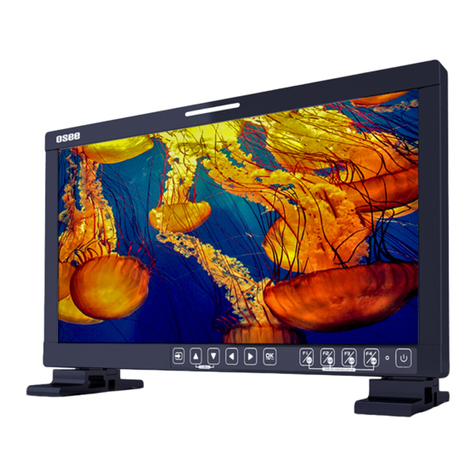
The control buttons are at the bottom of the screen, as shown in Figure 3.1-1.
Figure 3.1-1 Buttons in Front Panel
1. INPUT: Input selection button
2. F1: Function button
3. F2: Function button
4. F3: Function button
5. F4: Function button
6. F5: Function button
7. MENU: Menu operation button
8. UP: Menu operation button
9. DOWN: Menu operation button
10. ENTER: Menu operation
button
11. POWER/Lamp
12. TALLY: TALLY indicator(LED
TALLY)
3.1.2 Function of Control Buttons
INPUT Selection Button
Press INPUT button and toggle or use the UP/DOWN button to select and display
the corresponding signal input to each connector.

Locations and Function of Parts and Control
10
SDI1: monitor the SDI input as the active signal through the SDI1 IN
connector.
SDI2: monitor the SDI input as the active signal through the SDI2 IN
connector.
LINE1(CVBS): monitor the Composite Analog Input as the active signal
through the LINE1 IN connector.
LINE2(CVBS): monitor the Composite Analog Input as the active signal
through the LINE2 IN connector.
LINE2(Y/C): monitor the Composite Analog Input as the active signal
through the Y IN connector and CIN connector.
LINE2(YPBPR): monitor the Composite Analog Input as the active signal
through the YIN connector, Pb IN connector and Pr IN connector.
HDMI: monitor the HDMI or DVI input as the active signal through the HDMI
IN connector.
When switching an input source, it will display the SOURCE menu at the right top
corner of the screen, and the current active source is labeled in highlight yellow, as
shown in Figure 3.1-2.
SDI1
LINE1(CVBS)
LINE2(CVBS)
LINE2(Y/C)
SOURCE
SDI2
LINE2(YPBPR)
HDMI
Figure 3.1-2 Source Menu
Particularly, in PIP/PBP display mode, the signal source for the main picture is
set by INPUT button, while the slave picture’s is set through the CONFIGSUB
IN SELECT item in main menu, refer to “4.1.7 CONFIG Menu”for the details.
Function Buttons
F1~F5 button are all function buttons. Pressing any F button will display the
assigned Functions. Pressing the desired function will select the function. When
selected, the Function will then toggle through the desired setting including OFF.
The function of each button can be set via the FUNCTION KEY setting in the main

Locations and Function of Parts and Control
11
menu.
OPERATION: for example, press F1 to display the FUNCTION menu at the left
bottom corner of the screen, as shown in Figure 3.1-3. Toggle F1 button to
change the value related to this function without the setting value display.
F1 ONFLASE COLOR
F2 OFFNATIVE
FUNCTION
F3 OFFMONO
F4 OFFFREEZE
F5 OFFPBP
Figure 3.1-3 Function Menu
The FUNCTION menu will be closed automatically ten seconds after the last
button push.
You can assign various functions to each F1~F5 button through FUNCTION
KEY menu. Refer to "4.1.9 FUNCTION KEY Menu" for the details.
FACTORY RESET Function.
Press and hold the INPUT+F2 button for 3 seconds to access the menu in Figure
3.1-4.
Factory Reset Now?
No Yes
FACTORY RESET
Figure 3.1-4 Reset Menu
Menu Operation Buttons
Display or set the MAIN menu.
MENU Button
Used to activate MAIN menu.
Press to display the MAIN menu
Press again to clear the MAIN menu

Locations and Function of Parts and Control
12
UP
Used to navigate on-screen menu.
Toggle this button to select the previous item or increase the item value.
DOWN
Used to navigate on-screen menu.
Toggle this button to select the next item or decrease the item value.
ENTER
Used to navigate on-screen menu, confirm selection with the MAIN menu, or
load the Adjust menu.
MENU Selection and Setting
When displaying the MAIN menu, press ENTER button to select a menu item or
setting value, the active item is labeled in a highlight color, then press ENTER
button to confirm the settings, otherwise, press MENU button to give up the
modification and turn back the higher level menu item.
Refer to “4.2 Menu Settings”for detail about the MAIN Menu operations.
Adjust Menu-Adjust VOLUME, BRIGHTNESS, CONTRAST, CHROMA
When not displaying the MAIN menu, press ENTER button to display the
Adjust menu, as shown in Figure 3.1-5.
Toggle among these adjustable items: VOLUME, BRIGHTNESS, CONTRAST,
CHROMA.
BRIGHTNESS 50
Figure 3.1-5 Adjust Menu
After displaying the Adjust menu, press UP or DOWN button to adjust the item
value, and then press ENTER button to confirm the value setting. The
relationship of the items and their range is list in Table 3.1-1:
Table 3.1-1 The Description of Adjust Menu Items
Adjust Menu
Description
Range
Default
VOLUME
Adjust the volume
0~31dB
16
BRIGHTNESS
Adjust the image brightness
0~100
50
CONTRAST
Adjust the image contrast
0~100
50
CHROMA
Adjust the image monochroma
0~100
50
The Adjust menu will be closed automatically ten seconds after the last button

Locations and Function of Parts and Control
13
push.
Power Button and Indicator
Used to turn the power to place the monitor into standby mode/off.
When the device is off(Red), press the POWER button to turn it on. The power
indicator lights in green.
Flashing green indicates no signal is present (refer to section 3.1.1)
When the device is on, press the POWER button to turn it off. The power
indicator lights in red.
3.2 Rear Panel
For the arrangement of the rear panel of LCM170-E and LCM230-E are the same,
which are different from the LCM156-E’s.
The real panel of LCM156-E is shown as below, there are various input and output
interfaces at the rear panel of LCM156-E monitor.
Parts and Functions
Figure 3.2-1 The Rear Panel of LCM156-E Monitor
The interfaces numbered from 1 to 19 in red dotted rectangle are described as

Locations and Function of Parts and Control
14
follows:
1. Power Switch
Press this part to switch on or switch off the power.
Push the button to the “-”icon to switch on the power.
Push the button to the “”icon to switch off the power.
ON OFF
2. Power Input
Plug the power supply to this interface to provide power to the device.
The specification is 12V5ADC.
3. SDI1 IN, SDI2 IN(BNC)
Two SDI signal input interfaces, support multiple format HD/3G-SDI inputs.
4. SDI1 OUT, SDI2 OUT(BNC)
Two SDI signal output interfaces.
5. HDMI IN(HDMI)
One HDMI signal input interface, HDMI Type-Aconnector, support HDMI or DVI
signal.
6. Ethernet(RJ-45)
A 10/100M Ethernet interface. Provide connection to a computer for external
control.
7. GPI interface(RJ-45)
Reserved and not defined.
8. RS485 (RJ-45)
Reserved and not defined.
9. Line IN(Unbalanced signal RCA connector)
Two pairs of analog audio stereo input interfaces: AUDIO IN1 L, AUDIO IN1 R,
AUDIO IN2 L, AUDIO IN2 R.
Connect to the audio outputs of external device.
10. L OUT, R OUT(RCA)Audio Output
Two audio output interfaces: AUDIO OUTPUT L, AUDIO OUTPUT R.
Output the analog stereo signal. The output audio can be changed in AUDIO
settings.
11. Headphone Output Connector (3.5mm stereo Jack)
Other manuals for LCM215-E Series
1
This manual suits for next models
4
Table of contents
Other OSEE Monitor manuals

OSEE
OSEE MVM230 User manual

OSEE
OSEE LCM170-A User manual

OSEE
OSEE LCM156-A User manual

OSEE
OSEE LMW-200 SERIES User manual

OSEE
OSEE XCM-250-OLED User manual

OSEE
OSEE G7 4K ULTRAHD User manual

OSEE
OSEE LMD9014 User manual

OSEE
OSEE LCM156-E User manual

OSEE
OSEE BCM-170 Series User manual

OSEE
OSEE PRM1014 User manual

OSEE
OSEE LMW156 SERIES User manual

OSEE
OSEE FRM-173 Series User manual

OSEE
OSEE LMW-230 Series User manual

OSEE
OSEE RMD9024 User manual

OSEE
OSEE MVM-170 Series User manual

OSEE
OSEE LMW-171H User manual

OSEE
OSEE LCM215-E Series User manual

OSEE
OSEE RMD4342-HSC User manual

OSEE
OSEE BCM-230 Series User manual

OSEE
OSEE XCM-240 User manual