Pace ST 25 User manual

Operation and Maintenance Manual for the
SODRTEK®
ST 25 Soldering System
P/N 5050-0530
www.ekt2.com

TITLE PAGE
General Information
Introduction...........................................................................................................3
Specifications .......................................................................................................3
Parts Identification................................................................................................4
Safety
Safety Guidelines.................................................................................................5
System Set-Up
Mounting Options ....................................................................................................5
Tip & Tool Stand......................................................................................................6
Handpiece Connection............................................................................................6
System Power Up ..........................................................................................................6
Heater Burn In Procedure..............................................................................................6
Operation
Variable Temperature Control..............................................................................7
Temperature Dial Lock.........................................................................................7
LED Operation......................................................................................................7
Temperature Dial Adjustment ........................................................................................8
Corrective Maintenance
Power Source.......................................................................................................8
Handpieces...........................................................................................................9
Packing List....................................................................................................................9
Spare Parts ....................................................................................................................9
Service ..........................................................................................................................10
PACE LIMITED WARRANTY STATEMENT.................................................................10
Contact Information.......................................................................................................11
www.ekt2.com

General Information
Introduction
The ST 25 system is available in either 115 VAC or 230 VAC versions, which incorporates a highly
responsive SensaTemp (closed loop) control system providing up to 80 Watts of total power to a
single output channel. The 230 VAC version system bears the CE Conformity Marking, which
assures the user that it conforms to EMC 89/336/EEC.
The 115 VAC version systems conform to FCC Emission Control Standard, Title 47, Subpart B, Class
A. This standard is designed to provide reasonable protection against harmful interference when the
equipment is operated in a commercial environment.
Specifications
System Power Source Power Requirements
ST 25 Operates on 97-127 VAC, 50/60Hz, 90 Watts maximum at 115 VAC,
60Hz
ST 25E Operates on 197-253 VAC 50/60Hz, 80 Watts maximum at 230 VAC,
50Hz
Temperature Specifications
HandpiecesTip Temperature Range: 204 to 455°C (400 to 850°F) nominal.
Temperature Stability: ±1.1°C (±2°F) at idle from set tip temp.
NOTE: Actual minimum and maximum Operating Tip Temperatures may vary depending on
Handpiece, Tip Selection, and application.
EOS/ESD Specifications
The specifications shown below apply except on "Soft Ground Systems" which have a 1meg
ohm current limiting resistor and a label placed on the power source front panel referring to
EN 100015-1.
Tip-To-Ground Resistance: Less than 2 ohms.
AC Leakage: Less than 2 Millivolts RMS from 50Hz to 10MHz.
Transient Level: Less than 500mV peak, out to 100MHz.
www.ekt2.com

Parts Identification
Front Panel LED
Power Switch
Power Receptacle
AC Power Receptacle
Fuse Holder
F
Temperature Selection Dial
Earth Ground Receptacle
www.ekt2.com

Safety
Safety Guidelines
The following are safety precautions that personnel must understand and follow when using or
servicing this product.
1. POTENTIAL SHOCK HAZARD - Repair procedures on PACE products should be
performed by Qualified Service Personnel only. Line voltage parts may be exposed
when the equipment is disassembled. Service personnel must avoid contact with these
parts when troubleshooting the product.
2. To prevent personnel injury, adhere to safety guidelines in accordance with OSHA and
other applicable safety standards.
3. SensaTemp handpiece heaters and installed tips are hot when the handpiece is powered
on and for a period of time after power off. DO NOT touch either the heater or the tip.
Severe burns may result.
4. PACE Tip & Tool Stands and handpiece cubbies are designed specifically for use with
the associated handpiece and houses it in a manner that protects the user from
accidental burns. Always store the handpiece in its holder. Be sure to place the
handpiece in its holder after use and allow for cooling before storing.
5. Always use PACE systems in a well ventilated area. A fume extraction system such as
those available from PACE are highly recommended to help protect personnel from
solder flux fumes.
6. Exercise proper precautions when using chemicals (e.g., solder paste). Refer to the Material
Safety Data Sheet (MSDS) supplied with each chemical and adhere to all safety precautions
recommended by the manufacturer.
System Set-Up
Set up the ST 25 system using the following steps and associated drawings.
1. Store the shipping container in a convenient location. Reuse of these
containers will prevent damage if you store or ship your system.
2. Place the Power Switch in the “OFF” or “0” position.
Mounting Options
The ST 25 can be placed directly on a workbench or it also can also be mounted under a workbench
or shelf to conserve space (optional mounting bracket sold separately). To mount the system in
this way (ST 50 shown):
1. Mount the bracket in the desired location (fasteners not
supplied).
2. Insert the 2 Mounting Screws (head first) into the power
source mounting slots.
3. Place the washers over the screws.
4. Fit the power source between the bracket’s support arms
and place the screws into the slots on the support arms.
5. Place the nut on the screw and tighten by hand.
6. Angle the power source so the operator can see the front
panel easily.
7. Tighten the nuts with a wrench or pliers.
www.ekt2.com

Tip & Tool Stand
The Tip & Tool Stand can be mounted to the power source. If the system will be placed on the
workbench, this is recommended. If the ST 25 is to be mounted under the workbench or shelf, the
Tip & Tool Stand should not be mounted to the power source.
1. To attach the stand to the power source:
a) Insert the 2 large hex head Mounting Screws (head first)
into the lower “T” slot on the side of the power source case
as shown.
b) Place the Tip & Tool Stand beside the power source.
Insert ends of the 2 Mounting Screws into the 2 Tip & Tool
Stand mounting holes as shown.
c) Install a Thumb Nut onto the end of each Mounting Screw
and tighten Thumb Nuts.
2. Place the handpiece into its Tip & Tool Stand.
Handpiece Connection
Connect the handpiece connector plug into the Power Receptacle
in the following manner.
1. Align guide on connector with slot on power receptacle.
2. Insert connector into power receptacle.
3. Turn the connector housing clockwise to lock in place.
System Power Up
1. Insert the female end of the power cord into the AC Power Receptacle on the rear panel of
the power source.
2. Plug the prong end (male end) of the power cord into an appropriate 3 wire grounded AC
supply receptacle.
CAUTION: To insure operator and ESD/EOS safety, the AC power supply receptacle must be
checked for proper grounding before initial operation.
NOTE: Ensure that the system is placed in a well-ventilated area. Smoke will be generated
during the burn in cycle and while soldering. Fume extraction equipment is recommended
Heater Burn In Procedure
Use the following instructions to perform the Heater Burn In procedure.
1. Place the Power Switch in the “OFF” (0) position.
2. Ensure that the handpiece is connected to the power source. If a plastic cap is present on
the heater assembly, remove it and discard. The cap is used for shipping purposes only.
Place the handpiece in the Tip & Tool Stand.
3. Turn on the power source.
4. Turn the Temperature dial to 315°C (600 °F) for 10 minutes.
5. Next, increase the temperature to 427°C (800°F) for 15 minutes.
6. Turn off the power source.
CAUTION: The heater will be hot at the conclusion of the Burn In procedure.
NOTE: This procedure should be performed whenever a new handpiece or new heater is
connected to the system.
www.ekt2.com

Operation
Variable Temperature Control
Adjust the Variable Temperature Control Knob to the desired temperature
setting. Notice that the control panel has an outer graphic scale denoting
temperature in °C (Celsius) and an inner graphic scale denoting temperature in
°F (Fahrenheit). These numerical scales denote the set tip temperature times
100 (e.g., “3” on the outer scale is 3 x 100 or 300°C).
Temperature/Dial Lock
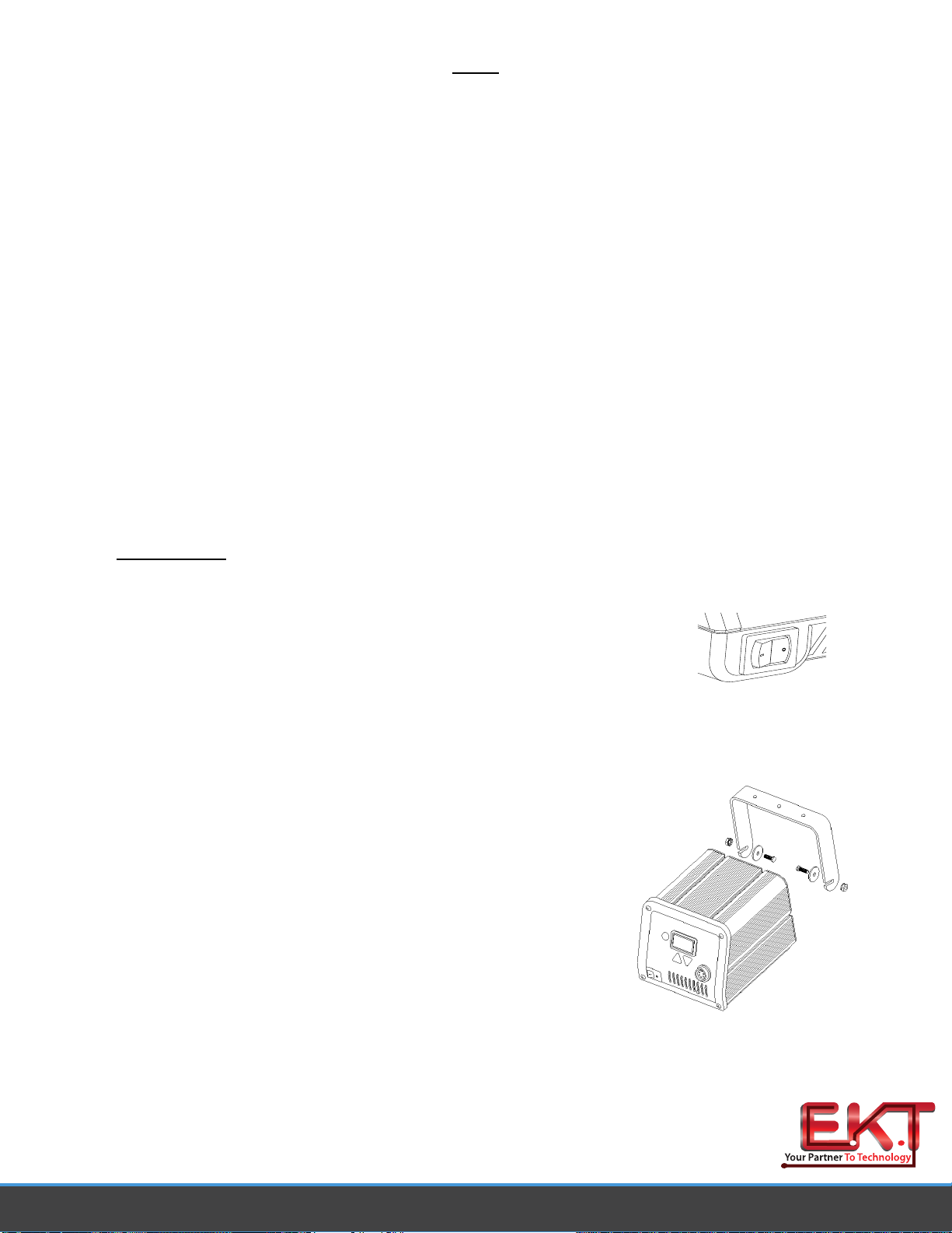
The Variable Temperature Control Knob can be locked in position to avoid accidental or unauthorized
changes of the temperature setting.
1. Adjust the Temp. Control Knob to the desired temperature setting.
2. Using the Temp. Locking Key (hex key supplied with system), tighten
the set screw on the Temp. Locking Ring closest to the front panel.
LED Operation
The Green colored LED on the power source front panel indicates System Status and Power
Receptacle output status (LED OFF, ON or Flashing).
LED Full On - Continuous power is being delivered to the handpiece. This
condition is evident when the system is first powered up (handpiece heater
cold) or the Variable Temperature Control setting is increased.
LED Flashing - Indicates that the set tip temperature (as set on the
Variable Temperature Control) has been reached. Power to the handpiece
is cycling Off and On to maintain set temperature.
LED Off - No power is being delivered to the handpiece heater. This condition is evident for a
short period of time when set temperature is reached and stabilizing or if the Variable
Temperature Control setting is decreased. If the LED never illuminates, check for a faulty
handpiece (see Corrective Maintenance section). Also, if no handpiece is connected to the
power source, the LED will not illuminate.
Temperature Dial Adjustment
The ST 25 system is tested for temperature accuracy at the factory and can be
checked for calibration according to PACE requirements. Also, a temperature setting
normally used by the operator can be adjusted to the precise temperature indicated on
the Dial/Display. No internal adjustments can be made to the power supply. To verify
calibration of the Temperature selection dial, perform the following procedure.
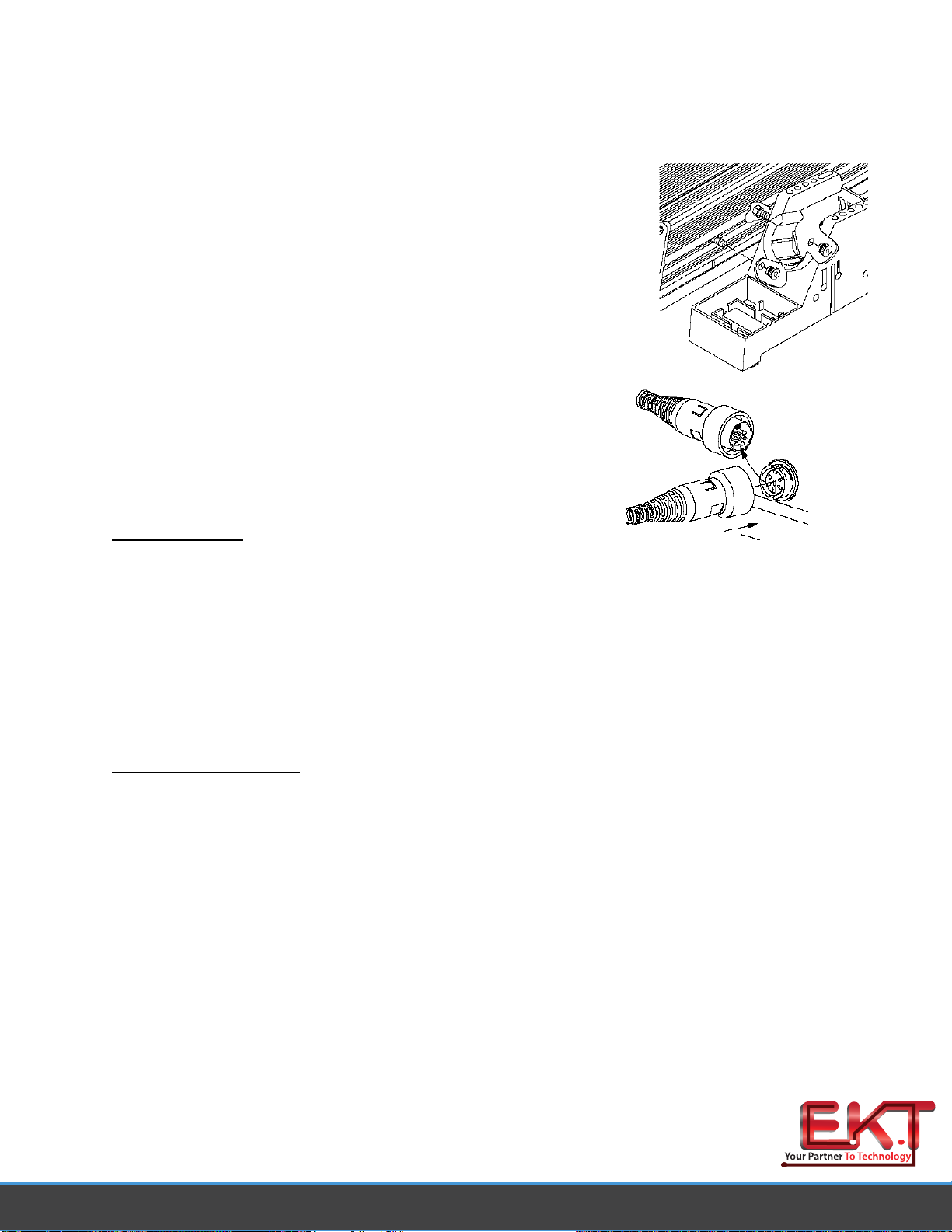
1. Install a tip with an embedded thermocouple into the handpiece connected to the system.
Tips with K type thermocouples are available from PACE.
2. Connect the thermocouple assembly to an appropriate temperature meter.
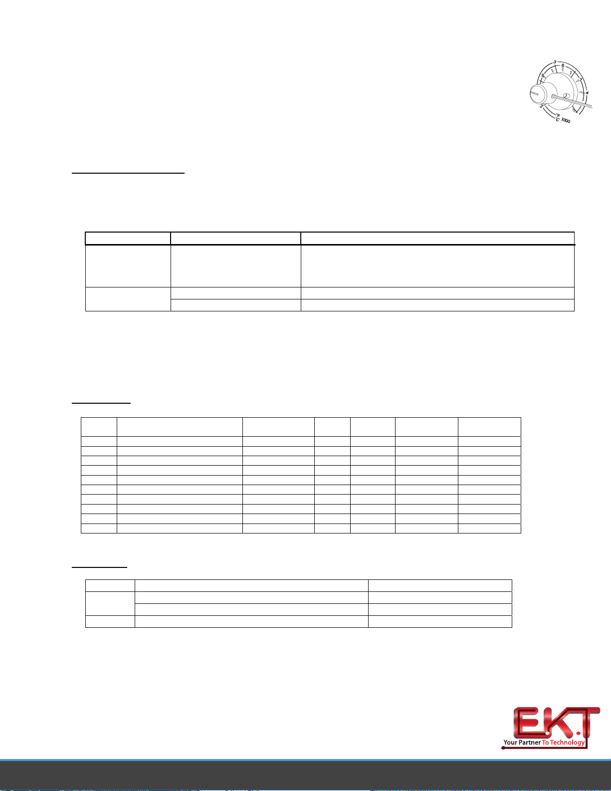
3. When set fully counterclockwise, the pointer of the Variable Temperature
Control knob will align to the Calibration Mark as shown. With the system
turned on, adjust the Variable Temperature Control to obtain a stable tip
temperature of 300°C (for PACE factory specifications) or the temperature
setting normally used by the operator.
If the temperature displayed on temperature meter is within ±15°C (27°F),
perform steps 4 thru 6 to obtain a precise reading. If the temperature is off by more than
www.ekt2.com

±15°C, the handpiece may require maintenance. Recheck the temperature using a
second handpiece.
4. Carefully lock the Variable Temperature Control in position by tightening the inner set
screw (closest to front panel).
5. Loosen the outer set screw on the Variable Temperature Control knob (furthest from front
panel) using the Temp. Locking Key (hex key) supplied with the system. Position the
knob with the pointer aligned to match the temperature indicated on the temperature
meter. Secure the knob in position by tightening the outer set screw.
6. Loosen the inner set screw to unlock the Variable Temperature control if adjustment of
operating tip temperature is desired.
Corrective Maintenance
Power Source
Most malfunctions are simple and easy to correct.
Symptom Probable Cause Solution
No power to
system Blown Fuse Check handpiece using the appropriate handpiece manual.
Replace the fuse (located in the AC Receptacle Fuse
Holder) with one of the same rated value.
Defective Heater Refer to the appropriate handpiece manualHandpiece will
not heat Power Source Malfunction Contact PACE
Power Source Corrective Maintenance
Handpieces
Please refer to the specific handpiece manual for the “Heater Assembly Checkout Procedures.”
Packing List
Item # Description Part Number ST 25
Only ST 25 E
Only ST 25 with
PS-90 ST 25E with
PS-90
1 System Power Supply 7008-0265-01 1 0 1 0
2 System Power Supply (Export) 7008-0265-02 0 1 0 1
3 PS-90 Handpiece Kit (51W) 6993-0199-P1 0 0 1 1
4 PS-90 High Capacity Chisel Tip 1121-0414-P5 0 0 1 1
5 Power Cord, 115V 1332-0094 1 0 1 0
6 Power Cord, 230V 1332-0093 0 1 0 1
7 Tip Tool 1100-0206 0 0 1 1
8 Hex Key, .050 1100-0237 1 1 1 1
9 Hot Grip Removal Pad 1100-0307 0 0 1 1
10 Operations Manual CD CD5050-0459 1 1 1 1
Packing List
Spare Parts
Item # Description PACE Part Number
Fuse, 1.0 Amp Time Lag (ST 25) 1159-0246-P51 Fuse, 1.0 Amp Time Lag (ST 25E) 1159-0213-P5
2 Optional Under Workbench Mounting Bracket 1321-0609-P1
www.ekt2.com

Operation and Maintenance Manual for the
PS-90 Soldering Iron Handpiece
Manual Number 5050-0443 Rev C
www.ekt2.com

Introduction
Thank you for purchasing the PACE model PS-90 Soldering Irons. These irons should only be used with
PACE SensaTemp compatible power supplies. This manual will provide you with the information
necessary to properly set-up, maintain and operate the PS-90.
Part Identification
English
1. Tip
2. Heater Assembly
3. Heater Set Screw
4. Heater Retaining Nut
5. Handle
6. Power Cable
English Language Safety Guidelines
The following are safety precautions that personnel must understand and follow.
1. Utilize all standard electrical safety precautions when using this or any other electrical equipment.
2. Always use this handpiece (and system) in a well ventilated area.
3. Do not leave the PACE system unattended when in use.
4. Repair on this product should be performed by Qualified Service Personnel only.
Set-Up
Tip & Tool Stand
The Tip & Tool Stand can be mounted to the power source. If the system will be placed on the workbench, this
is recommended. If the power source is to be mounted under the workbench or shelf, the Tip & Tool Stand
should not be mounted to the power source.
1. To attach the stand to the power source:
a) Insert the 2 Mounting Screws (head first) into the power
source mounting slots (plastic case shown). Slide the screws
toward the rear of power source.
b) Place the Tip & Tool Stand beside the power source. Insert
ends of the 2 Mounting Screws into the 2 Tip & Tool Stand
mounting holes shown.
c) Install a Thumb Nut onto the end of each Mounting Screw and
tighten Thumb Nuts.
2. Place the handpiece into its Tip & Tool Stand.
www.ekt2.com

PS-90 Tip Installation
For maximum productivity and proper fit, install tips into your soldering iron when the heater is hot
CAUTION: To avoid burns or potential injury, always hold the handpiece with the heater pointed at an angle
up to prevent injury.
1. Insert the Tip fully into heater bore using the supplied Tip Tool.
2. Gently tighten the heater Set Screw.
3. Recheck the tip Set Screw periodically to insure that it remains
snug.
PS-90 Heater Replacement
If replacement becomes necessary, perform the following procedure to ensure optimum performance and
maximize the life expectancy of the heater.
1. Allow the heater to cool.
2. Remove the Heater Retaining Nut.
3. Pull the Heater Assembly from the Handle. Discard defective Heater Assembly.
4. Align the connector key on the handle end of the replacement Heater Assembly with the keyway slot
on the handle.
5. Push the Heater Assembly fully into the handle.
6. Replace the Heater Retaining Nut and tighten by hand.
Spare Parts
Item # Description PACE Part Number
1 PS-90 Flat Ring 1500-0076-P5
2 PS-90 Heater Assembly (also fits PS-80) 6010-0095-P1
3 PS-90 Flared Ring 1500-0074-P5
4 Retaining Nut for PS-70/PS-90 1410-0122-P5
5 Heater Set Screws 1348-0547-P10
NOTE
Periodically, clean the heater bore with a properly sized
wire brush (3/16" O.D. to insure optimum heat transfer
and
p
ro
p
er ti
p
g
roundin
g
when.
Handpiece Connection
Connect the handpiece connector plug into the Power Receptacle
in the following manner.
1. Align guide on connector with slot on power receptacle.
2. Insert connector into power receptacle.
3. Turn the connector housing clockwise to lock in place.
Burn In Procedure
The following Burn In procedure must be performed to insure optimum performance and life
of this product:
1. Insure that system is located in a well-ventilated area on Initial power up.
2. Remove plastic cap from end of Heater Assembly (If present).
3. Connect Handpiece to PACE system Power Source.
4. Set Handpiece Tip temperature to 316°C (600°F). Burn Handpiece in for 10 minutes at this
temperature.
5. Set Handpiece Tip Temperature to 427°C (800°F). Heater Assembly will again emit smoke. Burn
Handpiece in at this temperature until emission of smoke ceases. Approximately 15 minutes.
6. Operate Handpiece in a normal manner.
www.ekt2.com
Other manuals for ST 25
2
This manual suits for next models
2
Table of contents
Other Pace Soldering Gun manuals