Pace ST 85 Manual
Operation & Maintenance Manual
ST 85 Systems

i
©2000PACEIncorporated,LaurelMD. Allrightsreserved. PrintedintheU.S.A.
PACE Incorporated retains the right to make changes to specifications contained
herein at any time, without notice.
Contact your local authorized PACE Distributor or PACE Incorporated to
obtain the latest specifications.
The following are registered trademarks and/or servicemarks of PACE
Incorporated, Laurel Maryland U.S.A. and may only be used to identify
genuine PACE products or services:
Arm-Evac,Flo-D-Sodr,Mini-Wave,PACE, SensaTemp,Snap-Vac,Sodrtek,
Sodr-X-Tractor, ThermoFlo,ThermoJet,ThermoTweez,Toolnet,Visifilter.
For any questions regarding this Operation & Maintenance Manual, contact your
local authorized PACE distributor or contact PACE directly at the appropriate address
listedbelow.
PACEUSA 9893 Brewers Court
Laurel, Maryland 20723-1990
Tel.: (301) 490-9860
(888) 535-7223 (PACE)
Fax (301) 498-3252
PACEEUROPE Sherbourne House, Sherbourne Drive
Tilbrook,MiltonKeynes
MK78HX
UnitedKingdom
Tel.: (44)1908 277666
Fax: (44)1908 277777
or
www.paceworldwide.com

MANUAL NUMBER 5050-0455
REV. C
1
SYSTEMQUICKSTART
The ST 85 system is very easy to operate and can be quickly
setupforuseinstandarddesoldering/solderingoperations.
Tobegin operationof yournewsystem quickly, perform
the "Set-Up" and "Quick Start - Basic Operation"
procedures detailed on pages 13-19 of this manual. A
shadedtitlebaroneachofthesepageshighlighttheirlocation.

2
Table of Contents
TITLE PAGE
GeneralInformation ................................................................................................. 4
Introduction ................................................................................................. 4
Specifications ............................................................................................... 4
Parts Identification ....................................................................................... 5
Safety ...................................................................................................................... 6
Safety Guidelines, English Language ........................................................... 6
Safety Guidelines, French Language ............................................................ 7
SafetyGuidelines,GermanLanguage ........................................................... 8
Safety Guidelines, Italian Language ............................................................. 9
Safety Guidelines, Portuguese Language ....................................................10
Safety Guidelines, Spanish Language .........................................................11
Safety Guidelines, Swedish Language .........................................................12
Set-Up ....................................................................................................................13
Stacking.......................................................................................................13
Tip & Tool Stand .........................................................................................13
Air Supply Connection................................................................................14
Handpiece Vacuum/Pressure .......................................................................15
Handpiece Connection ................................................................................17
System Power Up ........................................................................................17
Heater Burn In .............................................................................................17
QuickStart-BasicOperation .................................................................................19
Introduction ................................................................................................19
QuickStart Procedure ..................................................................................19
Operation ...............................................................................................................20
Definitions...................................................................................................20
Password .....................................................................................................21
Auto Tip Temperature Compensation .........................................................21
LEDDisplay-NormalOperation .................................................................22
LED Display - TemperatureAdjust Mode....................................................23
TemperatureSetback ...................................................................................24
Activation ..............................................................................................24
Operation ...............................................................................................24
ExitingTemperatureSetback ..................................................................25
Auto Off Safety System...............................................................................25
Operation ...............................................................................................25
ExitingAutoOff .....................................................................................25
QuickTour ...................................................................................................26
Factory Settings ..........................................................................................28
LEDDisplayAccuracy ................................................................................28

3
Table of Contents
TITLE PAGE
Set-Up Mode..........................................................................................................29
Introduction ................................................................................................29
Entering Set-Up Mode.................................................................................29
Operation.....................................................................................................30
Password................................................................................................30
TemperatureScale ..................................................................................30
TemperatureLimits .................................................................................31
Offset Constant......................................................................................32
TemperatureSetback ..............................................................................32
Auto Off.................................................................................................33
TemperatureDisplayImpedance ............................................................33
ExitingSet-UpMode ..............................................................................33
Corrective Maintenance .........................................................................................34
LED Display Message Codes ......................................................................34
PowerSource...............................................................................................35
Handpieces..................................................................................................36
Packing List/Spare Parts.........................................................................................37
PackingList .................................................................................................37
Spare Parts...................................................................................................37
LimitedWarrantyRegistrationForm.......................................................................38
TABLE PAGE
Table 1Factory Settings ..................................................................................28
Table 2LED Display Message Codes ..............................................................34
Table 3Power Source Corrective Maintenance................................................35
Table 4Heater Assembly Checkout Procedures ..............................................36
Table 5PackingList .........................................................................................37
Table 6Spare Parts ..........................................................................................37

4
Introduction
Thank you for purchasing the PACE model ST 85 Digital Desoldering/Soldering System.
This manual will provide you with the information necessary to properly set up, operate
and maintain the ST 85 system.
TheST85systemsareavailableineither the 115 VAC, or 230 VAC version which
incorporates a highly responsive SensaTemp (closed loop) control system providing up
to 80 Watts of total power to a single output channel. The 230 VAC version system
bears the CE Conformity Marking which assures the user that it conforms to all the
requirementsof council directive EMC 89/336/EEC. The systems package the power
source with a selection of accessories and functional aids.
The 115 VAC version system conforms to all the requirements of FCC Emission Control
Standard, Title 47, Subpart B, Class A. This system has been tested and found to
comply with the limits for a Class A digital device, pursuant to part 15 of FCC rules.
These limits are designed to provide reasonable protection against harmful interference
when the equipment is operated in a commercial environment. This equipment
generates, uses, and can radiate radio frequency energy and, if not installed and used in
accordance with this manual, may cause harmful interference to radio communications.
Operation of this equipment in a residential area is likely to cause interference in which
case the user will be required to correct the interference at his own expense.
General Information
Specifications
SystemPowerSourcePowerRequirements
ST 85-Operateson97-127VAC,50/60Hz,90Wattsmaximum
at115VAC,60Hz
ST85E-Operateson197-253VAC50/60Hz,80Wattsmaximum
at 230 VAC, 50Hz
ShopAirInputRequirements:
Pressure - 5.48Bar(80p.s.i.)recommended
6.17Bar(90p.s.i.)maximum
AirFlow-45.3SLPM(1.6SCFM)minimum
TemperatureSpecifications
Handpieces
TipTemperatureRange:204to482°C(400to900°F)nominal.
TemperatureStability:±1.1°C(±2°F)atidlefromsettiptemp.
NOTE-ActualminimumandmaximumOperatingTipTemperaturesmayvarydepending
on Handpiece, Tip Selection and application.
5
General Information
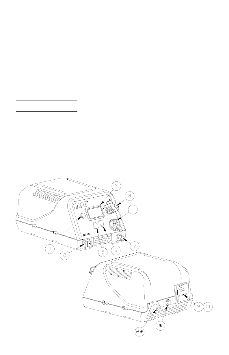
PartsIdentification
•Power Receptacle
‚Power Switch
ƒLED Display
„Program Key
…Scroll Up Key
†Scroll Down Key
‡Vacuum Port
ˆControllable Pressure Port
‰AC Power Receptacle/Fuse Holder
ŠFuse
SS Air Fitting
SEarth Ground Receptacle
(230 VAC sytems only)
EOS/ESDSpecifications
The specifications shown below apply except on "Soft Ground Systems" which have
a 1 meg ohm current limiting resistance and a label placed on the power source front
panelreferringtoEN100015-1.
Tip-To-Ground Resistance: Less than 2 ohms.
ACLeakage:Lessthan2millivoltsRMSfrom50Hzto10MHz.
TransientLevel: Lessthan500mV peak,outto100MHz.

6
Safety Guidelines - English Language
The following are safety precautions which personnel must understand and follow
when using or servicing PACE products.
1. POTENTIAL SHOCK HAZARD - Repair procedures on PACE
products should be performed by Qualified Service Personnel only.
Line voltage parts may be exposed when the equipment is disassembled.
Service personnel must avoid contact with these parts when
troubleshooting the product.
2. To prevent personnel injury, adhere to safety guidelines in accordance
with OSHA and other applicable safety standards.
3. SensaTemp handpiece heaters and installed tips are hot when the
handpiece is powered on. DO NOT touch either the heater or the tip.
Severe burns may result.
4. PACE Tip & Tool Stands and handpiece cubbies are designed
specifically for use with the associated handpiece and houses it in a
manner which protects the user from accidental burns. Always store the
handpiece in its holder. Be sure to place the handpiece in its holder after
use and allow to cool before storing.
5. Always use PACE systems in a well ventilated area. A fume extraction
system such as those available from PACE are highly recommended to
help protect personnel from solder flux fumes.
6. Exercise proper precautions when using chemicals (e.g., solder paste).
Refer to the Material Safety Data Sheet (MSDS) supplied with each
chemical and adhere to all safety precautions recommended by the
manufacturer.
Safety

7
Directives de Sécurité, Française Langue
Les précautions suivantes, sont celles que le personnel doit comprendre et suivre
lorsqu'il utilise, effectue la maintenance ou se sert d'un produit PACE.
1. Dangerpotentiel de chocèlectrique - Les procédures de réparation sur
les produits PACE doivent être effectuées seulement par du personnel
qualifié. Des parties de l'équipement désassemblées peuvent être sous
tension. Le personnel de maintenance doit éviter tout contact avec ces
parties en réparant le produit.
2. Pour prévenir tout préjudice, le personnel adhère au guide de sécurité en
accord avec OSHA (équivalent à des normes françaises de sécurité) et
d'autres standards de sécurité applicable.
3. La mise sous tension des outils SensaTemp comporte des éléments
chauffants (buse). Ces derniers, gardent la chaleur même après la mise
hors tension pendant un certain temps. Ne pas toucher les parties
chaudes aux extrémités des outils. Des brûlures sévères peuvent en
résulter.
4. Les outils PACE et leurs pannes ainsi que le support sont dessinés de
manière spécifique afin de protéger l'utilisateur/opérateur de brûlures
accidentelles. Reposer toujours les outils après chaque utilisation dans
leurs étuis/supports afin de permettre leur refroidissement.
5. Utiliser toujours les stations Pace dans unlieu bien ventilé. Des
extracteurs de fumée Pace sont hautement recommandés pour protéger
votre personnel des vapeurs de soudure/flux.
6. Prenez les mesures nécessaires quand vous utilisez des produits (ex:
solder paste) chimiques. Reportez-vous au document (fiche technique/
sécurité) du fabricant fourni avec chaque produit. Respectez toutes les
procédures de sécurité recommandées par le constructeur.
Sécurité

8
Sicherheit Korrekturlinien, Deutsche Sprache
Die nachfolgenden Sicherheitsvorschriften sollten vom Bedien- un Servicepersonal
verstanden und befolgt werden.
1. EntladungspannungsfuehrenderTeile-ReparaturenanPACEProdukten
sollten nur von qualifizierten Personal durchgefuehrt werden.
Spannungsfuehrende Teile koennen sich bei gezogenen Netzstecker
entladen. Servicepersonal muss den Kontakt dieser Teile vermeiden.
2. Um moegliche Gefahren fuer Personen auszuschliessen, muessen alle
Sicherheitsvorschriften in Uebereinstimmung mit OSHA und anderen
anwendbaren Sicherheitsstandards eingehalten werden.
3. Angeschlossene SensaTemp Heizelemente von Handwerkzeugen und
installierte Loetspitzen sind heiss wenn das System eingeschaltet ist oder
erst vor kurzer Zeit ausgeschaltet wurde. Heizelement und Loetspitze
nicht beruehren. Verbrennungsgefahr.
4. PACE Tip & Tool und andere Handwerkzeugablagen sind so konstruiert,
dass ein versehentliches Beruehren des dazugehoerendes
Handwerkzeuges vermieden wird. Bewahren Sie das Handwerkzeug nach
Gebrauch stets in der Ablage auf. Bevor das Handwerkzeug an einem
anderen Ort gelagert werden muss, lassen Sie es in der Werkzeugablage
vollstaendig abkuehlen.
5. Benutze PACE Systeme nur in gut beluefteten Raeumen. Ein
Loetrauchabsaugsystem, wie es z.B. von PACE erhaeltlich ist, hilft
Bedienpersonen von den Gefahren von Loetrauch zu schuetzen.
6. Wenn Chemikalien (z.B.: Lotpaste) verwendet werden, muessen alle die in
den Sicherheitsdatenblaettern des Herstellers ausgewiesenen
Sicherheitsvorschriften eingehalten werden.
Sicherheit
This manual suits for next models
1
Table of contents
Other Pace Soldering Gun manuals


Pace
Pace 5050-0552 User manual

Pace
Pace ST 25 User manual

Pace
Pace HW 100 HeatWise User manual

Pace
Pace MBT 201 Manual

Pace
Pace MBT 350 User manual

Pace
Pace SODRTEK ST 125 User manual

Pace
Pace ST 25 User manual

Pace
Pace ADS200 User manual

Pace
Pace WJS 100 User manual

Pace
Pace Sodr-X-Tractor SX-80 User manual


Popular Soldering Gun manuals by other brands


Velleman
Velleman HRJA151 user manual

Weller
Weller WSM 1 operating instructions

Vishay Precision Group
Vishay Precision Group Micro-Measurements Mark V Operating and maintaining

ersa
ersa i-CON 1V quick guide

Hakko Electronics
Hakko Electronics FX-100 instruction manual

Weller
Weller WAD 101 operating instructions


