manuals.online logo
Brands
  1. Home
  2. •
  3. Brands
  4. •
  5. Pace
  6. •
  7. Soldering Gun
  8. •
  9. Pace TD-100 User manual

Pace TD-100 User manual

Other manuals for TD-100

3

Other Pace Soldering Gun manuals

Pace MBT360 User manual

Pace

Pace MBT360 User manual

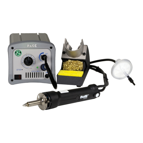
Pace ST 65 Manual

Pace

Pace ST 65 Manual

Pace Sodr-X-Tractor SX-80 User manual

Pace

Pace Sodr-X-Tractor SX-80 User manual

Pace MicroBenchtop MBT-100 Troubleshooting guide

Pace

Pace MicroBenchtop MBT-100 Troubleshooting guide

Pace MBT 350 User manual

Pace

Pace MBT 350 User manual

Pace MBT 301 Instruction Manual

Pace

Pace MBT 301 Instruction Manual

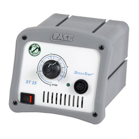
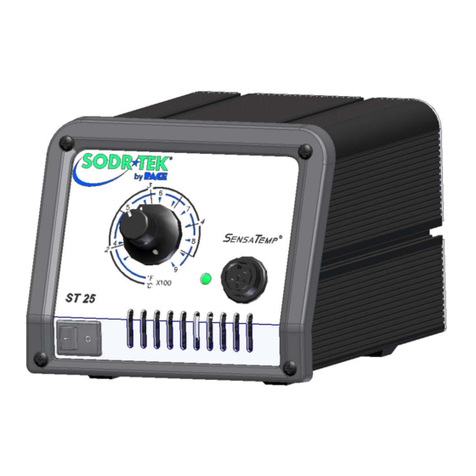
Pace ST 25 User manual

Pace

Pace ST 25 User manual

Pace ST 40A Manual

Pace

Pace ST 40A Manual

Pace SX-100 User manual

Pace

Pace SX-100 User manual

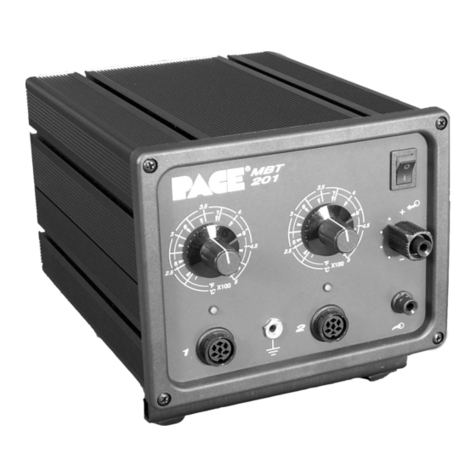
Pace MBT 201 Manual

Pace

Pace MBT 201 Manual

Pace ST 35 User manual

Pace

Pace ST 35 User manual

Pace MBT250 Manual

Pace

Pace MBT250 Manual

Pace Sodrtek HW50 User manual

Pace

Pace Sodrtek HW50 User manual

Pace MBT250E-SDSoftGround Instruction manual

Pace

Pace MBT250E-SDSoftGround Instruction manual

Pace ST 85 Manual

Pace

Pace ST 85 Manual

Pace TJ-70 Instruction Manual

Pace

Pace TJ-70 Instruction Manual

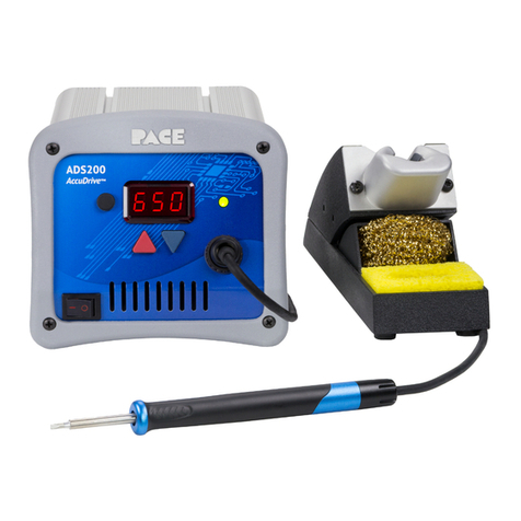
Pace ADS200 Instruction manual

Pace

Pace ADS200 Instruction manual

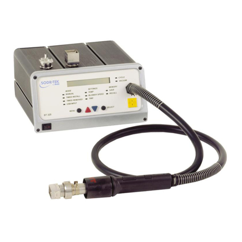
Pace SODRTEK ST 325 User manual

Pace

Pace SODRTEK ST 325 User manual

Pace ST 45 User manual

Pace

Pace ST 45 User manual

Pace ST 25 User manual

Pace

Pace ST 25 User manual

Pace ADS200 User manual

Pace

Pace ADS200 User manual

Pace MBT 350 User manual

Pace

Pace MBT 350 User manual

Pace SODRTEK ST 125 User manual

Pace

Pace SODRTEK ST 125 User manual
Pace ST 25 User manual

Pace

Pace ST 25 User manual

Popular Soldering Gun manuals by other brands

FTM Technologies SI1R user manual

FTM Technologies

FTM Technologies SI1R user manual

Bakon 3200 instruction manual

Bakon

Bakon 3200 instruction manual

Proxxon Gaslotset MGS manual

Proxxon

Proxxon Gaslotset MGS manual

jbc SFR-A instruction manual

jbc

jbc SFR-A instruction manual

jbc CL8010 instruction manual

jbc

jbc CL8010 instruction manual

Hakko Electronics FX-100 instruction manual

Hakko Electronics

Hakko Electronics FX-100 instruction manual

HAKO FX-8804 instruction manual

HAKO

HAKO FX-8804 instruction manual

SATA 02002A user manual

SATA

SATA 02002A user manual

Velleman HRJA151 user manual

Velleman

Velleman HRJA151 user manual

Weller WSM 1 operating instructions

Weller

Weller WSM 1 operating instructions

Vishay Precision Group Micro-Measurements Mark V Operating and maintaining

Vishay Precision Group

Vishay Precision Group Micro-Measurements Mark V Operating and maintaining

ersa i-CON 1V quick guide

ersa

ersa i-CON 1V quick guide

Atten ATETOOL AT-689A user manual

Atten

Atten ATETOOL AT-689A user manual

Surtek 112554 User manual and warranty

Surtek

Surtek 112554 User manual and warranty

Parkside PLBS 30 A1 Operation and safety notes

Parkside

Parkside PLBS 30 A1 Operation and safety notes

AlienTek T100 user manual

AlienTek

AlienTek T100 user manual

Weller FT12 operating instructions

Weller

Weller FT12 operating instructions

ersa RA 4500 D operating instructions

ersa

ersa RA 4500 D operating instructions

manuals.online logo
manuals.online logoBrands
  • About & Mission
  • Contact us
  • Privacy Policy
  • Terms and Conditions

Copyright 2025 Manuals.Online. All Rights Reserved.

www.paceworldwide.com
Solutions and systems for soldering, rework and repair of electronics www.paceworldwide.com
Process Guide I-QFP-02
QFP Installation
Mini Wave
Equipment Required
PACE Intelliheat®Power Supply
TD-100 Thermo-Drive®Soldering Iron
Mini-Wave®Tip (See Chart on Back)
Tip Tool
HP-65 HandiPik®
Optional Equipment
Tweezer
Materials
Flux-cored Solder
Flux
Cleaner
Procedure
1. Set a tip temperature of 343°C (650°F) for lead-free
or 316°C (600°F) for leaded alloys and adjust as
necessary.
2. Install selected Mini-Wave®tip into the TD-100 using
Tip Tool.
3. Position the component ensuring proper lead-to-land
alignment. Hold the component in place using the
HandiPik®or tweezers.
4. Apply flux and tack solder opposing corner leads.
5. Apply flux to ALL lead/land areas.
6. Clean tip on Tip & Tool Stand sponge.
7. Apply solder to the cupped portion of tip to create a
convex bead of molten solder.
8. Position Mini-Wave®tip so the solder bead contacts
the top portion of leads. Slowly move tip over one row
of leads to form proper solder fillets at each joint.
9. Repeat steps 6 through 8 on remaining sides of
component.
10. Re-tin Mini-Wave®tip with solder. Return TD-100 to
its Tip & Tool Stand.
11. Clean, if required, and inspect.
A
A
B
C
Position Component
C
Flux Leads
B
Tack Lead
D
Fill Tip
© 1997, 2001, 2012 PACE, Incorporated. Hand Soldering Manual for Rework/Repair & Assembly
(001) 910-693-8620 (USA) 877-882-7223
TD-100
D
E
E
Solder Component
Solutions and systems for soldering, rework and repair of electronics www.paceworldwide.com
Process Guide I-QFP-02
TD-100 Tips
© 1997, 2001, 2012 PACE, Incorporated. Hand Soldering Manual for Rework/Repair & Assembly
(001) 910-693-8620 (USA) 877-882-7223
Tips Description Tip Size - L Size - D Part Number
MiniWave®N/A 3.05mm (.120") 1124-0032-P1
Angled MiniWave®N/A 3.05mm (.120") 1124-0033-P1
Single Sided Chisel N/A 3.05mm (.120") 1124-0034-P1
Angled MiniWave®N/A 2.11mm (.083") 1124-0035-P1
Single Sided Chisel, Fine Pitch N/A 1.5mm (.06") 1124-0038-P1
Angled MiniWave®, Fine Pitch N/A 1.6mm (.064") 1124-0039-P1
MicroFine Single Sided Chisel N/A 0.9mm (.035") 1124-0040-P1
MicroFine Single Sided Chisel N/A 1.1mm (.045") 1124-0041-P1
Angled Micro-Wave N/A 1.1mm (.045") 1124-0045-P1
Micro-Wave N/A 1.1mm (.045") 1124-0046-P1
Single Sided Chisel 17.00mm (0.693") 4.55mm (0.178") 1124-0048-P1
MiniWave®N/A 2.79mm (0.110") 1124-0049-P1