Pall Allegro User manual

Allegro™ 200 L Single- se Mixer
USD 2743
Instructions For se

Contents
1. Introduction ............................................................................................................................3
2. Warning...................................................................................................................................3
3. Receipt of Equipment ............................................................................................................3
4. System Pictures and Schematics .........................................................................................4
5. System Installation and Operation ........................................................................................6
Connections to the User Control Interface (UCI) ......................................................................6
Safety Interlocks (micro-switches) Check .................................................................................7
Allegro Mixer Tote & Single-use System – Pre Installation Checks ...........................................9
System Installation .................................................................................................................10
Mixer Bag Inflation .................................................................................................................15
Adding Fluid and Solids to the Single-use Mixer System........................................................17
Operating the Mixer ...............................................................................................................19
6. Drain/Removal Instructions .................................................................................................21
7. roubleshooting....................................................................................................................23
8. Specification ables .............................................................................................................24
9. General Maintenance Recommendations...........................................................................25
10. WEEE Compliance. Reuse, Recycling and Recovery (2002/96/EC)..................................26
11. CE Declaration......................................................................................................................27
2USD 2743

1. Introduction
The following procedures are provided for installation of the Pall Allegro 200 single-use mixer
incorporating Allegro 3D mixer biocontainers with a capacity of 200 . The instructions
contained in the product documentation should be read thoroughly because they contain
valuable information gained by extensive experience. It is very important that all instructions are
carefully followed and, where appropriate, they should be incorporated into the user’s standard
operating procedures. If some of the procedures do not suit your needs, please consult Pall or
your local distributor before finalizing your system. Use of this product in a manner other than in
accordance with Pall’s current recommendations may lead to injury or product loss. Pall cannot
accept liability for such injury or loss.
2. Warning
Operation outside the specifications defined in the product data sheet or with fluids
incompatible with materials of construction may cause personal injury and result in damage
to the equipment. Incompatible fluids are fluids that may chemically attack, soften, stress,
attack or otherwise adversely affect the materials of construction. Please refer to Pall for
exact limits for contact fluids and conditions.
3. Receipt of Equipment
Allegro 200 mixer hardware:
1. Use appropriate equipment when removing the mixer hardware from the shipping container.
2. Take care when removing the supplied mixer hardware from the shipping container.
3. ocate or store the hardware in an appropriate indoor location. The equipment is designed
for operation in clean rooms and classified areas and as such should be maintained in a
clean state and stored when not in use in an appropriate clean location free from adverse
environmental conditions.
4. Only use mixer when brakes are engaged on the castors.
5. Do not attempt to move tote during mixing.
6. Use on even surface.
Caution:
The UCI is configured for correct operation prior to delivery and is therefore not required
to be opened during normal operation. The UCI should only be opened by a qualified
servicing engineer.
Allegro single-use systems are typically sterilized by gamma irradiation.
1. Store the Allegro 3D system in clean, dry conditions between 4 and 40 °C without
exposure to radiation sources like direct sunlight and, wherever practical, in the
packaging as delivered.
2. Do not remove from packaging until just before use.
3. Check that the packaging is undamaged prior to use.
Caution:
1. Avoid the use of sharp blades or pointed instruments that could damage the
Allegro mixer system and other system components.
2. Do not open the packaging by forcing any of the system components through
the sealed end because this can generate particulate contaminants.
3. Ensure that the system selected is suitable for the application.
4. The single-use system used in the Allegro 200 L mixer unit is designed for
single use only.
3
USD 2743 www.pall.com/biopharm

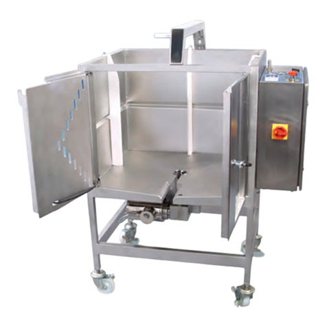
4. System Pictures and Schematics
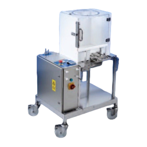
Figure 1
Allegro single-use mixer tote (with mixer biocontainer)
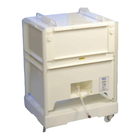
Figure 2
Allegro single-use mixer biocontainer
4USD 2743
Motor & Gear
Box
Full Access
Doors
Support Arm
Mixer Tote
User Control
Interface (UCI)
Mixer
Biocontainer
Flush Outlet
Port & Valve
4 Pitch Blade
Turbine Impeller
Inlet Port Plate
Impeller Cover &
Powder Port
Gas Inlet
Gas Return
Fluid Inlet
Powder Inlet

Figure 3
Allegro mixer tote (open ready to accept single-use system)
Figure 4
Allegro mixer tote with mixer system installed
5
USD 2743 www.pall.com/biopharm

5. System Installation and Operation
Connections to the User Control Interface (UCI)
1. Connect the power cord to the power outlet according to the specified voltage and current
of your unit (power as per specification table, see section 8).
Caution:
Ensure the power cable is not positioned underneath the tote to avoid potential fluid contact.
2. Check that the ‘BAG INF ATION’ switch is set to the ‘OFF’ position as shown below.
Figure 5
Bag inflation switch position on start-up
3. Connect the gas (house air/nitrogen) line to the supply (shown below, ‘SUPP Y’) on the
UCI using suitably rated and sized pneumatic tubing (gas supply as per specification table,
see section 8) as shown in Figure 6 below.
Figure 6
Connection of the gas supply to the UCI
4. Check that the doors are closed and the handle is in the vertical (closed) position
(see Figure 9).
5. Power-up the unit by turning the main supply switch to the ‘ON’ position (from horizontal
to vertical as shown in Figure 7 below), which is on the front of the UCI.
Note: Power to the unit is indicated by illumination of the ‘DOO ’ interlock light on
the UCI (assuming the doors and handle have been closed as per item 4 above)
as indicated in Figure 7 below.
6USD 2743

Figure 7
System UCI showing power switch
Safety Interlocks (micro-switches) check
1. Open the doors of the mixer tote.
2. Depress the shaft micro switch (Figure 8).
3. Check that the appropriate ED (labelled ‘SHAFT’) on the UCI is illuminated green. If the
‘SHAFT’ ED is not illuminated green at this stage, refer to ‘Troubleshooting’, section 7.
Figure 8
Depressing the ‘SHAFT’ micro switch to confirm it is working prior to system installation
4. Close the doors to the tote and rotate the handle clockwise fully so that it is in the secured
(closed) position (vertical) as shown in Figure 9 below.
7
USD 2743 www.pall.com/biopharm
Power Switch

Figure 9
Activating the ‘DOO ’ micro switch by closing the doors
5. Check that the appropriate ED (labelled ‘Door’) on the UCI is illuminated green (Figure 9).
If the ‘DOOR’ ED is not illuminated green at this stage, refer to ‘Troubleshooting’, section 7.
6. Depress the support arm micro switch (Figure 10).
Figure 10
Depressing the support arm micro switch to confirm correct operation prior to system installation
7. Check that the appropriate ED (labelled ‘SUPPORT’) on the UCI is green (Figure 10). If the
‘SUPPORT’ ED is not illuminated green at this stage, refer to ‘Troubleshooting’, section 7.
Assuming correct operation of all safety micro switches, the system is now ready for installation
of the Allegro single-use mixer system.
8USD 2743
Micro Switch

Allegro Mixer ote & Single-use System – Pre Installation Checks
Preparation of the mixer tote:–
1. Open the doors fully and ensure that the internal surfaces of tote are undamaged, clean,
dry, and free from particulate matter (Figure 3).
2. If using baffles in the mixer system ensure these are located in the correct position prior to
inserting the single-use system (Figure 11). Note that baffles can be used with low viscosity
fluids when using high motor revolutions per minute (rpm), to restrict the formation of
vortices and potential air entrapment within the solution. They can also be used at low
volumes (50 ) to reduce air entrapment and vortices generation during operation.
Figure 11
Mixer tote with (3) baffles installed prior to single-use system installation and installing
the baffles
Allegro single-use system check:
1. Carefully open the protective bags containing the single-use system using appropriate
tools such as a safety knife so as not to damage any part of the system, and remove
Allegro Mixer system from its packaging (retaining any appropriate labels as necessary).
2. Take care not to snag any parts of the tubing assemblies or additional system components
when removing the system (ensure the packaging is fully open to allow easy removal of
the system).
3. Check the system is as specified
• Part numbers supplied
• Tubing inlets and outlet lengths
• Types of connections
• Powder port top cap and clamp
• Outlet port plate (See Figure 13)
• Check the system is undamaged
9
USD 2743 www.pall.com/biopharm
Baffles

System Installation
1. Install Allegro single-use system into the mixer tote.
A. Holding the system securely as shown below (Figure 12) align the shaft on the single-
use system, with the tube support in the centre of the mixer tote and the inlet port
plate to the right hands side of the impeller cover.
Figure 12
Holding the system (top left) ready to place system impeller shaft into the tube support mechanism
(top right) on the mixer tote and showing the system installed with doors open (bottom)
10 USD 2743

B. Ensure the locating plate on the outlet port is aligned with the channel at the front of
the mixer tote (Figure 13).
Figure 13
Carefully lifting the mixer biocontainer to ensure the locating plate on the outlet port is
in correct location
2. Check that the appropriate ED (labelled ‘SHAFT’) on the UCI is illuminated green as
shown in Figure 14 below. If the ‘SHAFT’ ED is not illuminated green at this stage,
please refer to ‘Troubleshooting’ (Section 7).
Figure 14
‘SHAFT’ interlock illuminated indicating correct location of shaft
11
USD 2743 www.pall.com/biopharm
Locating Plate

3. Before closing the doors attach the inflation and exhaust tubing to the UCI and secure
with cable ties. The ¼ inch line (Gas Inlet on Figure 2) connects to the ‘IN’ hosebarb on the
UCI and the ½ inch tubing (Gas Return on Figure 2) connects to the ‘OUT’ line on the UCI
as shown in Figure 15 below.
Figure 15
Inflation (IN) and exhaust (OUT) lines connected to the UCI
Note: Depending on system design it may be necessary to cut the ends of the inflation
and exhaust lines in order to allow fitment over the hose barbs on the UCI.
4. Check that the tubing on the fluid inlet line (see Figure 16) is securely clamped shut.
Figure 16
Check fluid inlet port is closed
12 USD 2743

5. Check that the flush outlet port on the single-use system is not open
(see Figures 17 and 18 below).
Figure 17 Figure 18
Flush outlet port closed Flush outlet port open (prior to filling)
6. Carefully lift up the overhanging front section of the mixer biocontainer and close the doors,
starting with the left hand side door first, ensuring the system locating plate is located
under the closed door (Figure 19).
Figure 19
Closing the doors ensuring the system locating plate remains under the doors
13
USD 2743 www.pall.com/biopharm
System Locating Plate
✓✓
✘

7. Turn the handle to the ‘closed’ (vertical position, Figure 20) to secure, check that the
appropriate ED on the UCI (labelled ‘DOOR) is illuminated (Figure 21). If the ‘Door’ ED
is not illuminated green at this stage, please refer to the Troubleshooting Table (Section 7).
Figure 20
Handle to ‘closed’ (vertical) position
Figure 21
Securing the doors and checking the door micro switch is energized
8. Check the inside of the mixer tote to ensure no parts of the single-use system are
snagged or trapped.
9. ock the doors with the supplied key and remove (Figure 22).
Note: The key can only be removed from the handle when in the ‘locked’ position.
Figure 22
Locking the doors and removing the key
14 USD 2743

Mixer Bag Inflation
1. Check the gas inlet and gas return lines are securely fastened to the hose barbs.
2. On the UCI, turn the valve which supplies gas to the single-use mixer system to the
‘ON’ position (Figure 23).
Figure 23
Gas inflation valve in the ‘ON’ position
Note 1: During inflation of the mixing biocontainer, ensure that the tubing supplying
gas to the biocontainer does not get trapped between the tote and the biocontainer.
Note 2: The inflation process will take around 5 minutes. The UCI will control the inflation
pressure during this step. If inflation stops at any point before full inflation is achieved,
please refer to the Troubleshooting table under section 7.
3. When full inflation is achieved, the system will maintain the pressure in the single-use
system between 4 – 10 mbar.
4. Secure the support arm of the mixer tote to the powder port of the single-use mixer
system (Figure 24).
Figure 24
Powder port support arm in correct location
15
USD 2743 www.pall.com/biopharm
Powder Port
Support Arm

5. Once installed, check that the appropriate ED on the UCI (labelled ‘SUPPORT’)
is illuminated, indicating that the powder port is correctly supported by the mixer
hardware. If the ED is not illuminated green at this stage, please refer to the
Troubleshooting table under section 7.
Figure 25
System inflated (regulated to 4 – 10 mbar) and support arm connected to the powder port,
energizing the ‘SUPPO T’ micro switch/interlock
Note: When the SHAFT, DOO and SUPPO T interlocks are energized, the EADY
light illuminates, indicating the system is ready to accept fluid and begin mixing.
Also the speed controller for the mixer will also be energized and will show the
word ‘STOP’ (See Figure 29).
16 USD 2743

Adding Fluid and Solids to the Single-use Mixer System
Fluid Addition:
1. Connect the fluid inlet line to the main fluid supply using a suitable connection (Figure 26).
Figure 26
Fluid inlet line connected to fluid source using an appropriate connection method
(dependent on application requirements and system design)
2. Open the clamp on the filling inlet to the single-use mixer system and commence filling
of the system to the desired volume (between 50 – 200 ). Fluid flowrate into the system
should be up to a maximum flowrate of 20 /min.
Note: during the fluid filling process, the pressure in the mixer biocontainer will increase
slightly to approximately 10 – 20 mbar.
Caution:
When adding bulk fluid monitor the pressure on the bag inflation gauge (Figure 27)
to make sure it does not increase above 20 mbar.
If it does increase above 20 mbar, reduce the fluid filling rate into the system.
17
USD 2743 www.pall.com/biopharm
Figure 27
UCI showing higher pressure (10 – 20 mbar) during fluid filling due to the pressure caused
by fluid addition. Do not allow this to increase above 20 mbar.
3. Stop filling when the desired volume in the mixer biocontainer is achieved.
Solids Addition:
A. Switch the bag inflation control valve to the ‘OFF’ position.
B. Using either a suitable powder transfer biocontainer with the desired mass of solid,
or via simply adding the measured amount via a funnel, add the desired mass of
solids to the fluid volume. When the powder port is opened, the pressure in the
mixer biocontainer will drop to zero (Figure 28).
Figure 28
Bag inflation set to ‘OFF’ for powder addition, where the pressure in the biocontainer
will drop to zero
18 USD 2743

Caution:
Do not overfill the mixing biocontainer!
Do not open the tote doors once the mixing biocontainer is full or partially filled with fluid.
Caution:
Ensure bag inflation valve is set to ‘off’ position prior to opening the powder port.
Operating the Mixer
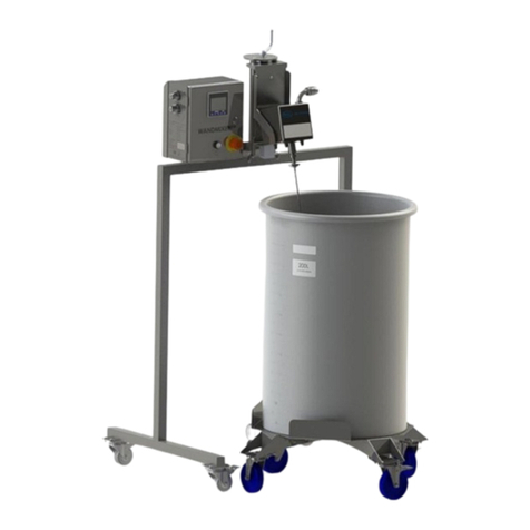
The mixer speed (revolutions per minute – rpm) and direction of rotation are controlled by
the panel on the UCI. The mixer can be rotated in a counter-clockwise direction to provide
‘down-flow’ pumping action to the fluid or in a clockwise direction to provide ‘up-flow’
pumping action on the fluid.
Note: Maximum life (continuous mixing) is 3 days (72 hours).
Figure 29
Setting the impeller speed (rpm) for the mixer
19
USD 2743 www.pall.com/biopharm
STOPRUN
AUTO FWD
RUN
REV
M
RF
To set the rpm/speed for the
rotation, use the panel to
increase the rpm figure to the
desired value.

Figure 30
Changing the direction of rotation of the impeller
Figure 31
Starting and stopping the mixer
20 USD 2743
STOPRUN
AUTO FWD
RUN
REV
M
RF
The direction of rotation is set as either
‘FWD’ or ‘REV’.
FWD = Counter-clockwise/Downflow
REV = Clockwise/Up-flow
To change from current direction:
1. Press
Either FWD or REV will flash for approx
4 seconds, indicating the new direction
2. Press within 4 seconds
This will activate rotation in the
opposite direction
RF
M
Having set the rpm
and direction, to
start the mixer press
‘RUN’. The mixer
will ramp up to the
desired speed.
STOPRUN
AUTO FWD
RUN
REV
M
RF
To stop mixing press
‘STOP’. The mixer
will ramp down to
a stop (0 rpm).
Other manuals for Allegro
1
Table of contents
Other Pall Laboratory Equipment manuals

Pall
Pall Allegro 1000 L User manual

Pall
Pall Minimate EVO User manual

Pall
Pall Allegro MMG403 User manual

Pall
Pall Allegro 50 L User manual

Pall
Pall Envirochek User manual

Pall
Pall Allegro User manual

Pall
Pall Minimate EVO TFF User manual

Pall
Pall WandMixer RDUA003A User manual

Pall
Pall T Series Guide

Pall
Pall Allegro 200 L User manual
Popular Laboratory Equipment manuals by other brands

Novatech
Novatech SCILogex MX-T6-Pro user manual

Thermo Savant
Thermo Savant UVS400 instruction manual

GE
GE AKTAprocess operating instructions

Thermo Scientific
Thermo Scientific Orion ROSS Ultra user manual

vitro
vitro MD STAINER QUICK GUIDE TO TECHNICAL INSTRUCTIONS FOR USE AND CLEANING

Scientifica
Scientifica SliceMate manual