3
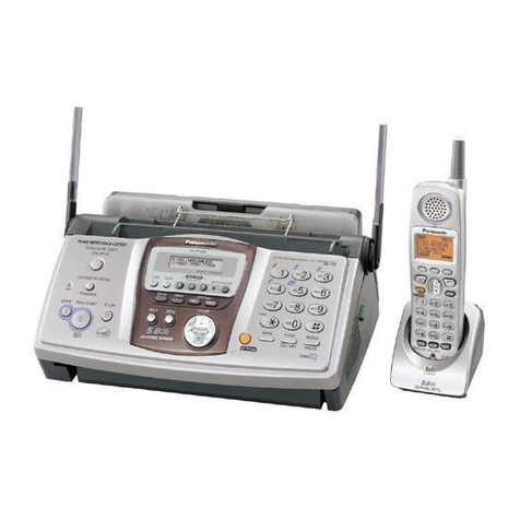
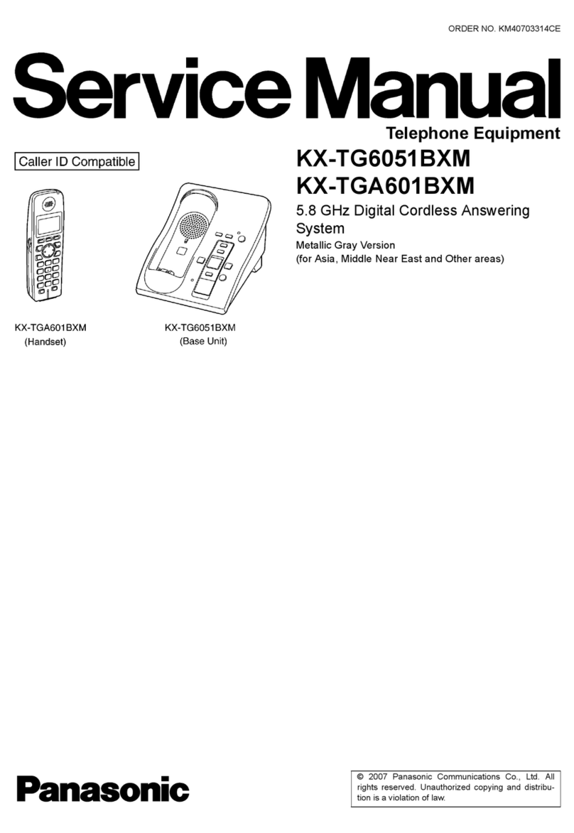
KX-TG6700BXB/KX-TGA670BXB
TABLE OF CONTENTS
PAGE PAGE
1 Safety Precautions----------------------------------------------- 4
1.1. For Service Technicians --------------------------------- 4
2 Warning -------------------------------------------------------------- 4
2.1. Battery Caution--------------------------------------------- 4
2.2. About Lead Free Solder (Pbf: Pb free)--------------- 4
3 Specifications ----------------------------------------------------- 6
4 Technical Descriptions ----------------------------------------- 7
4.1. FHSS Description ----------------------------------------- 7
4.2. Explanation of Link Data Communication ----------10
4.3. Block Diagram (Base Unit_Main)---------------------11
4.4. Block Diagram (Base Unit_RF Part)-----------------12
4.5. Circuit Operation (Base Unit)--------------------------13
4.6. Block Diagram (Handset_Main)-----------------------23
4.7. Block Diagram (Handset_RF Part)-------------------24
4.8. Circuit Operation (Handset)----------------------------25
4.9. Circuit Operation (RF Part)-----------------------------29
4.10. Circuit Operation (Charger Unit) ----------------------34
4.11. Signal Route -----------------------------------------------35
5 Location of Controls and Components ------------------37
5.1. Controls -----------------------------------------------------37
5.2. Displays -----------------------------------------------------38
6 Installation Instructions ---------------------------------------39
6.1. Setting Up the Base Unit -------------------------------39
6.2. Setting Up the Handset ---------------------------------42
6.3. Battery Installation/Replacement ---------------------42
6.4. Battery Charge --------------------------------------------42
7 Operation Instructions-----------------------------------------44
7.1. Symbols Used in These Operating
Instructions -------------------------------------------------44
7.2. Programmable Settings ---------------------------------45
7.3. Error Messages -------------------------------------------49
7.4. Troubleshooting-------------------------------------------50
8 Test Mode ----------------------------------------------------------53
8.1. Adjustment and Test Mode Flow Chart -------------53
9 Service Mode -----------------------------------------------------61
9.1. How to Clear User Setting------------------------------61
10 Troubleshooting Guide ----------------------------------------62
10.1. Troubleshooting Flowchart -----------------------------62
10.2. How to Replace the Flat Package IC----------------75
10.3. How to Replace the LLP (Leadless Leadframe
Package) IC------------------------------------------------77
11 Disassembly and Assembly Instructions ---------------79
11.1. Disassembly Instructions -------------------------------79
11.2. Fix the LCD and the Receiver Guide to the
Main P.C.Board (Handset) -----------------------------82
12 Measurements and Adjustments---------------------------83
12.1. Things to Do after Replacing IC ----------------------83
12.2. Base Unit Reference Drawing-------------------------84
12.3. Handset Reference Drawing---------------------------85
12.4. Frequency Table ------------------------------------------86
13 Schematic Diagram ---------------------------------------------88
13.1. For Schematic Diagram---------------------------------88
13.2. Schematic Diagram (Base Unit_Main) --------------90
13.3. Schematic Diagram (Base Unit_RF Part) ----------94
13.4. Schematic Diagram (Base Unit_Operation) -------96
13.5. Schematic Diagram (Handset_Main) ----------------98
13.6. Schematic Diagram (Handset_RF Part) ---------- 100
13.7. Schematic Diagram (Charger Unit) ---------------- 102
14 Printed Circuit Board ---------------------------------------- 103
14.1. Circuit Board (Base Unit_Main) -------------------- 103
14.2. Circuit Board (Base Unit_RF Part)----------------- 105
14.3. Circuit Board (Base Unit_Operation)-------------- 107
14.4. Circuit Board (Handset_Main) ---------------------- 109
14.5. Circuit Board (Handset_RF Part) -------------------111
14.6. Circuit Board (Charger Unit)--------------------------112
15 Appendix Information of Schematic Diagram --------113
15.1. CPU Data (Base Unit) ---------------------------------113
15.2. CPU Data (Handset) -----------------------------------115
15.3. Explanation of IC Terminals (RF Part) -------------116
15.4. Terminal Guide of the ICs, Transistors and
Diodes -----------------------------------------------------119
16 Exploded View and Replacement Parts List --------- 120
16.1. Cabinet and Electrical Parts (Base Unit)--------- 120
16.2. Cabinet and Electrical Parts (Handset)----------- 121
16.3. Cabinet and Electrical Parts (Charger Unit)----- 122
16.4. Accessories and Packing Materials --------------- 123
16.5. Replacement Parts List------------------------------- 125
