manuals.online logo
Brands
  1. Home
  2. •
  3. Brands
  4. •
  5. ParaBody
  6. •
  7. Fitness Equipment
  8. •
  9. ParaBody 894 User manual

ParaBody 894 User manual

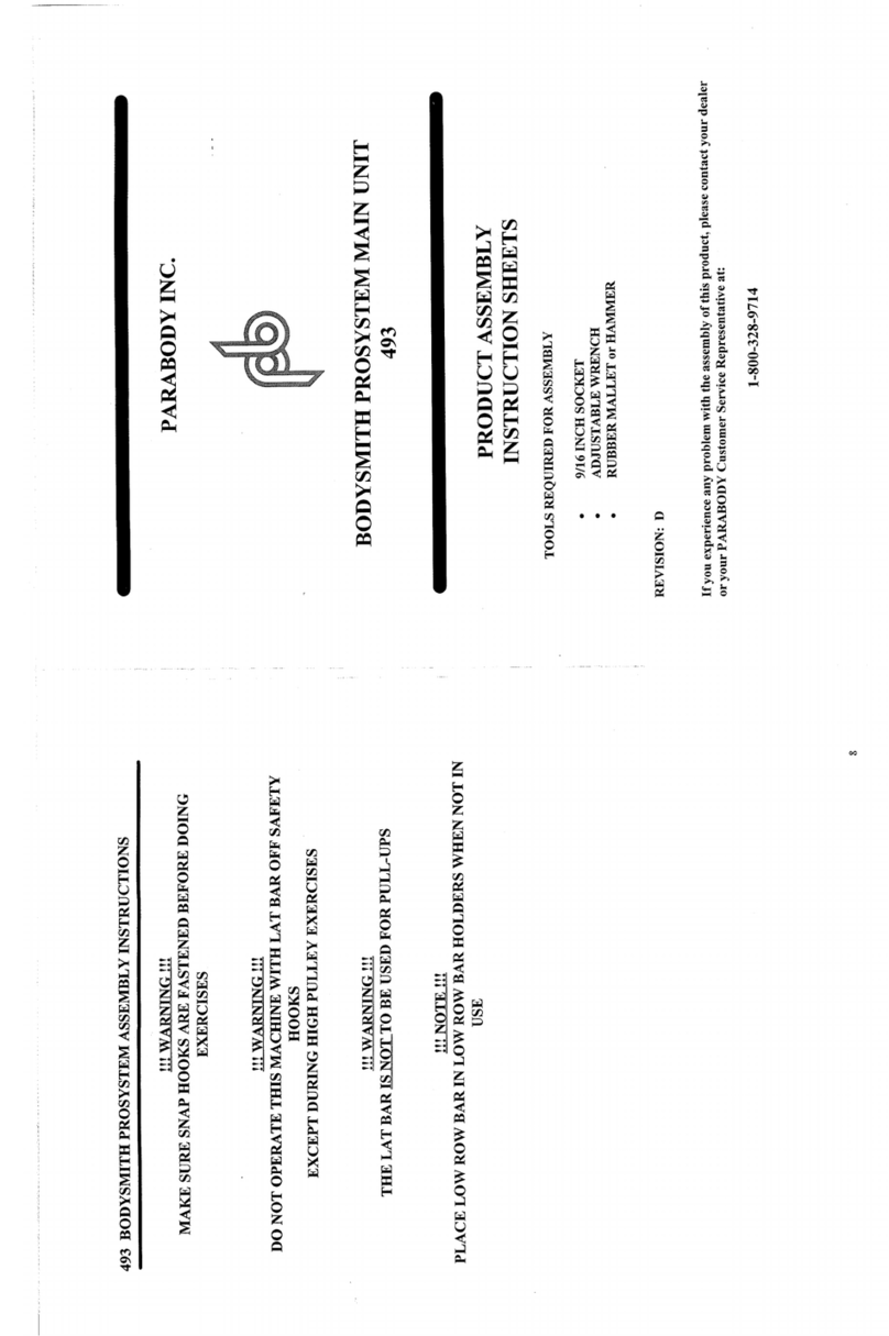
PARABODY INC.
PROSYSTEM PEC DEC OPTION
894
ASSEMBLY
INSTRUCTIONS
TOOLS REQUIRED FOR ASSEMBLY
3/4 INCH SOCKET
9/16 INCH SOCKET
ADJUSTABLE WRENCH
RUBBER MALLET or HAMMER
REVISION: A
If you experience any problemxvith the assemblyof this product, please contact your dealer
or your PARABODYCustomer Service Representative at:
1-800-328-9714
894 PROSYSTEM PEC DEC OPTION PARTS LIST
SORT AND COUNTALL PARTS BEFORE BEGINNING ASSEMBLY
HARDWARE:
ITEM NAM:E/DESCRIPTION QTY
2.
3.
4.
5.
6.
7.
8.
9.
10.
11.
12.
13.
14.
15.
16.
17.
18.
19.
20.
21.
1/2 X 3-1/2 IN. BOLT
3/8 X 3-1/4 IN. BOLT
3/8 X 3 IN. BOLT
3/8X2IN.BOLT................................................................................................................... 2
3/8X’1-3/4IN.BOLT............................................................................................................. 2
5/16 X1IN.BOLT................................................................................................................. 2
1/2 IN, WASHER.................................................................................................................... 4
3/8 IN, WASHER
5/16IN.WASHER.................................................................................................................. 4
I/2IN.LOCKWASHER........................................................................................................ 2
3/8IN.LOCKWASHER........................................................................................................ 6
5/16IN.LOCKWASHER...................................................................................................... 2
I/2IN.NUT............................................................................................................................ 2
3/8IN.NUT............................................................................................................................ 4
5/16IN.NUT.......................................................................................................................... 2
1/4IN.QUICKLINK............................................................................................................. 1
CABLERETAININGCLIP.................................................................................................... 3
STARLOCKCOLLAR.......................................................................................................... 2
FLANGEBEARING.............................................................................................................. 4
2IN.SQ.ENDCAP................................................................................................................ 9
PLASTICSTOPS.................................................................................................................... 2
NOTE: BOLT LENGTHIS MEASUREDFROMTHE UNDERSIDE OF THE HEAD OF THE BOLT.
Iiiiiii!1
BOL,T LENGTH
BOLTLENGTHRIULER:
I!/2 I !/2 I1/2 I I/2 I la I ln--I
2345_L I 6
O. 1
894 PROSYSTEM PEC DEC OPTION PARTS LIST
"SORT AND COUNT ALL PARTS BEFORE BEGINNING ASSEMB.~Y
WELDMENTStl’ARTS: Q’]FY
ITEM NAME/DESCRIPTION
BEARINGHOUSING.................................................... (6259703)........................................ 1
l. PULLEYMOUNTSUPPORT........................................ (6258603)........................................ 1
2.
3. PECoDECARMRIGHT................................................. (6187903)....................................... 1
4. PEC-DECARMLEFT.................................................... (6187603)....................................... 1
5. ¯ LOWERPLILLEYSUPPORT........................................ (6260403)....................................... 1
6. PULLEYLOOPBRACKET........................................... (6260303)........................................ 1
7. BACKPAD..................................................................... (6457501)........................................ 1
8. 4X12ROI.LERPAD..................................................... (6176201)....................................... 2
9. SECONDARYSWAP-OUTCABLE............................. (6259901)....................................... 1
10. LOOPCAE’,LE.~.............................................................. (6259801)....................................... l
i I. 4-1i20.D.XI IN. BUSHINGPULLEY........................ (3116101)....................................... 4
894
NOTE:
10.
II.
12."
13.
PROSYSTEM PEC DEC OPTION ASSEMBLY INSTRUCTIONS
Removethe SECONDARYCABLEby disassembling the CABLEfrom its ,M.,~IX UPRIGIII’I"
CONNECTIONPOINT, and pull CABLEout from the LOWPULLEYSTATION. (NOTIE:
REMOVELG,W PULLEY FOR EASE OF REMOVAL)
Insert four (4) 2 IN. SQ.ENDCAPSinto all open ends of the BEARINGltOt.!SING.
Insert one (I) ";’. IN. SQ. ENDCAPinto the end of the PULLEYMOUNTSUPPORT,
SECURELY~ssemble both the BEARINGHOUSINGand the PULLEYMOUNTSUPPOR’[ to the
MAINUPRIGHTof the BODYSMITHPROSYSTEM,using two (2) I~ X 3-I,r2 IN. BOLI’S, four
1/2 IN. WASHERS,two (2) t/2 IN. LOCKWASHERS,and two (2) 1,2 IN. NUIS.
THE CONNECTORPLATES ON THE BEARING HOUSINGAND TIlE PI.:i, LEY MOUNT
SUPPORT HA.VE OVAL HOLES. MOVETHE BEARING HOUSING DO~,VN AND TIlE PULLEY
MOUNTSUPPORT UP AS FAR AS POSSIBLE. SEE-DRAWING
CAREFULLYinsert tour (4) FLANGEBEARINGSinto the TOPand BOTTOMside~ of the
BUSHINGSof the BEARINGHOUSINGon both sides. (CAUTION: DONOTOVERTAP TItESE
BEARINGS INTO PLACE, WHICH CAN CAUSE DEFORMATIONTO TIlE BEARINGS,
MAKING THEM UNUSABLE)
Insert four (4) 2 IN. SQ. ENDCAPSinto BOTHENDSof the LEFTand RIGliT PEC-DECARMS.
Insert the LEFT and RIGHTPEC-DECARMSthrough the FLANGEBEARINGSin the BEARING
HOUSINGon their respective sides, and secure them in place with two (2) STARLOCKCOLLARS.
Attach two (2) PLASTICSTOPSto the CAMSTOPon the BEARINGHOUSING,approximately where
shown, in orde.r to give the PEC-DECARMCAMSfull contact whenthe PEC-DECARMS~tre in their
restingpositio~a.
Slide two (2) 4 X 12 ROLLERPADSonto the LEFTand RIGHTPEC-DECARMS.until the ROLLER
PADis FLUSHwith the bottom of the ARMS.(NOTE:IF A LUBRICANTIS REQUIRED,RUBBING
ALCOHOLTHOROUGHLYCOATINGTHE INSIDE OF THE ROLLERIS TIlE BF2~-I"
MATERIALTO USE. ALSO, ROTATINGTHE PAD ~’HILE PUSHING UP WILL llELP TO
EASE ASSEMBLY)
LOOSELYassemble two (2) 4-1/20.D. XI IN. BUSHINGPULLEYSand tx~o {2} CAIILI:’.
RETAININGCLIPS to the PULLEYMOUNTSUPPORT.usiqg tx~o (2~
IN. LOCKWASHERS,and two (2) 3/8 IN. NUTS.(NOTE: Tills CONNECTIONX~II..i.
TIGHTENED AFTER THE CABLE HAS BEEN ROUTED)
LOOSELYassemble the BACKPADto the TOPHOLEof the MAINVPRIGltI. u,,mg t~,ne ( i } 3;g X
IN. BOLT,one (1) 3/8 IN. LOCKWASHER,and one (!) 3,’8 IN. ~,VASllER
Using one (1)3/8 X3-I/4 IN. BOLT,and one (I)3i8 IN. LOCKWASIIER.SECtREI.~’ assemble
LOWERPULLEYSUPPORTthrough the BOTTOMHOLEof the MAINUI’RIf;liT and into the
BACKPAD. (NOTE: MAKESURE THAT THE BASE PLATE OFTilE L¢)~ t:R I’ILLEY
SUPPORTIS FLUSHWITHTHE SIDES OF THE MAINUI’RI(;IIT. SEE I)R.~I~(J;I
TIGHTENthe BOLr in STEP! I.
NOTE:
PROSYSTEIVI PEC DEC OPTION ASSEMBLY INSTRUCTIONS.,
SECURELYas:~emble one (I) 4-I ’20.D. X 1 IN. BUSttlNGPUI.LEYto the LO\
~, ERPULLEY
SUI’PORT.using one (I) 3/8 X I-3/4 IN. BOLT,one (I) 3/8 I,OCKWASHER,a,~d o,~e (1) 3/8 IN.
LOOSELYassemble one (1) 4-1/20.D. X I IN. BUSIIINGPULLEYand one (1) CABLERETAINING
CLIP to the PULLEYLOOPBRACKET,using one (1) 3/8 X 1-3/4 IN. BOLT,one (1) 3/8 IN.
WASHER,and one (1) 3/8 IN. NUT.(SEE DETAIL
BEFORE PROCEEDING WITH CABLE INSTALLATION, UNRAVEL CABLE, AND REMOVE
AS MUCHSPIRALING AS POSSIBLE.
To install LOOPCABLE(PB2598-1), start by SECURELYassembling both ends of the LOOPCABLE
to the CAMSof the LEFTand RIGHTPEC-DECARMS,using two (2) 5/16 X 1 IN. BOLTS,four (4)
5/16 IN. WASHERS,two (2) 5/16 IN. LOCKWASHERS,and two (2) 5/16 IN. NUTS.(NOTE:
SURE THE CABLE ENDS REST FLAT AGAINST THE INSIDE OF THE CAMS) (SEE DETAI[L
C)
Drape both sides of the CABLEover the PULLEYSon the PULLEYMOUNTSUPPOR’r.Position
CABLERETAININGCLIPS on the PULLEYMOUNTSUPPORTin a vertical position over the
PULLEYand CABLE,after the LOOPCABLEhas been routed. Tighten the PULLEYCONNECTION
completely.
Place the PULLEYon the PULLEYLOOPBRACKETover the LOOPof the CABLEcreated from the
above step. Position the CABLERETAININGCLIPin a vertical position under the CABLEand
PULLEY. Tighten PULLEYCONNECTIONcompletely. (NOTE: MAKESURE THATTHE
CABLE IS IN THE GROOVEOF THE PULLEY BEFORE TIGHTENING)
See CABLEROUTINGDIAGRAMfor help in completing STEP 16.
To install SECONDARYSWAP-OUTCABLE(PB2599-1), start by inserting the end of the CABLE,
WITHOUTthe WHITE BALL under the FRONTPULLEYin the LOWROWPULLEYIHOUSING
on the MAIN UPRIGHT. (REMOVEPULLEY FOR EASE OF INSTALLATION)
Push the CABLEunder the FRONTPULLEYand througl: the HOLEof the MAINUPRIGHTto the
PULLEYon the UPRIGHTBRACEof the MAINUPR!CHT. Pull CABLEuntil the WHITEBALL
stops against the FRONTPULLEYand the LOWROWPULLEYHOUSING.
Pull the CABLEaround the BRACEPULLEYand up to the SECONDPULLEYon the PULLEY
BLOCK SYSTEM. (NOTE: THE CABLE MUST BE ROUTED AROUNDTHE SECOND PULLEY
FROM THE REAR TO THE FRONT)
Pull CABLEaround the SECONDPULLEYof the PULLEYBLOCKSYSTEMand down to the
PULLEYon the LOWERPULLEYSUPPORT.Pull CABLEaround underneath the PULLEY,and
attach it to the HOLEof the PULLEYLOOPBRACKET,using 1/4 IN. QUICKLINK. (SEE DETAIL
A)
See CABLEROUTINGDIAGRAMfor help in completing STEP 17.
If assembling the PECDECOPTIONand the MAINUNITat the same time, return to the I~/IAIN UNIT
ASSEMBLYIINSTRUCTIONS,and continue on with STEP 25.
.)
UNG
~I~ × z
---BACK PAD
3/6 LOCKWA~IAER--~
PULLEY MOUNTSUPPORT
1/2. WASHER(2)
I/Z. LOCKWASHER(Z)
I/Z. NUT(Z)
2 SQ. END CAP
4--1/2 X 1 IN. BUSHING
PULLEY(2)
.3/8 X .3 BOLT
.3/8 X 1-.3/4 BOLT
-- 4--1//2 X 1 IN.
BUSHINGPULI_EY
3/(5 WA3HER
.3//8 X 5-1//4 BOLT
.3//8 NUT
,3//8 LOCKWASHER(,3)
;Q. ENDCAP(4)
;K COLLAR(2)
:(2)
OLT (2)
DETAIL"(..’"
//
/
//
LO0~ C.AI~LE CABL E
DETAIL
S~4AP OUT
¯ ;PECDECARM,RIGHT
PEC DECARM,LEFT
IFLANGEBEARING(4.
BEARINGHOUS
PLASTIC ST(.
MUMbleR
,
4 X 12 OLLERPAD (2)
2 SQ. ENDCAP(4)
STARLOC
1/2 WASHER
LD’,!Kb.RSHER
7~-zl’-I/~. ,, I It,,l. BUSI41t4G
"~lB /PULLEY
NUT=/
~~ I-3/4
BOLT
1
~/-~~ - PISLLEYLOOP
BRACKET
CABLFRETA~NIN
CLIP
1/2 X ,3-1/2 B
DETAt L

Other ParaBody Fitness Equipment manuals

ParaBody 858102 Mounting instructions

ParaBody

ParaBody 858102 Mounting instructions

ParaBody 848101 User manual

ParaBody

ParaBody 848101 User manual

ParaBody Serious Steel Pro System User manual

ParaBody

ParaBody Serious Steel Pro System User manual

ParaBody 880 User manual

ParaBody

ParaBody 880 User manual

ParaBody 886101 User manual

ParaBody

ParaBody 886101 User manual

ParaBody 883101 User manual

ParaBody

ParaBody 883101 User manual

ParaBody 883 User manual

ParaBody

ParaBody 883 User manual

ParaBody 877101 Mounting instructions

ParaBody

ParaBody 877101 Mounting instructions

ParaBody 802101 Mounting instructions

ParaBody

ParaBody 802101 Mounting instructions

ParaBody 827102 User manual

ParaBody

ParaBody 827102 User manual

ParaBody 832101 User manual

ParaBody

ParaBody 832101 User manual

ParaBody 843 User manual

ParaBody

ParaBody 843 User manual

ParaBody 872101 Mounting instructions

ParaBody

ParaBody 872101 Mounting instructions

ParaBody 861 Mounting instructions

ParaBody

ParaBody 861 Mounting instructions

ParaBody Serious Steel 835102 User manual

ParaBody

ParaBody Serious Steel 835102 User manual

ParaBody 867101 Mounting instructions

ParaBody

ParaBody 867101 Mounting instructions

ParaBody 888101 User manual

ParaBody

ParaBody 888101 User manual

ParaBody 887101 User manual

ParaBody

ParaBody 887101 User manual

ParaBody 868 Mounting instructions

ParaBody

ParaBody 868 Mounting instructions

ParaBody 824 User manual

ParaBody

ParaBody 824 User manual

ParaBody 875 Mounting instructions

ParaBody

ParaBody 875 Mounting instructions

ParaBody 855103 User manual

ParaBody

ParaBody 855103 User manual

ParaBody 821 User manual

ParaBody

ParaBody 821 User manual

ParaBody GS2 User manual

ParaBody

ParaBody GS2 User manual

Popular Fitness Equipment manuals by other brands

Finnlo Autark 2500 manual

Finnlo

Finnlo Autark 2500 manual

MTS Systems HIEMT user manual

MTS Systems

MTS Systems HIEMT user manual

ABS AbSolo owner's manual

ABS

ABS AbSolo owner's manual

Adidas Performance Deluxe Utility Bench Assembly manual

Adidas Performance

Adidas Performance Deluxe Utility Bench Assembly manual

SLG Stair Climber user manual

SLG

SLG Stair Climber user manual

VIEQUIPMENT Viroller user manual

VIEQUIPMENT

VIEQUIPMENT Viroller user manual

Matrix MAGNUM 2003M quick start guide

Matrix

Matrix MAGNUM 2003M quick start guide

SPORT ELEC Multisport Pro user manual

SPORT ELEC

SPORT ELEC Multisport Pro user manual

Zelart SUB1101U Assembly instructions

Zelart

Zelart SUB1101U Assembly instructions

VBX Wellness 5000 manual

VBX Wellness

VBX Wellness 5000 manual

Master MASSPSB-18 quick start guide

Master

Master MASSPSB-18 quick start guide

Weider PRO 800 user manual

Weider

Weider PRO 800 user manual

FITFIU FITNESS RA-200 instruction manual

FITFIU FITNESS

FITFIU FITNESS RA-200 instruction manual

Crane FITNESS 91779 instructions

Crane

Crane FITNESS 91779 instructions

Gima TD001P-2 user manual

Gima

Gima TD001P-2 user manual

Sport-thieme 11 144 1707 Assembly manual & exercise instructions

Sport-thieme

Sport-thieme 11 144 1707 Assembly manual & exercise instructions

TOORX RowerCompact instruction manual

TOORX

TOORX RowerCompact instruction manual

Hoist Fitness Club Series owner's manual

Hoist Fitness

Hoist Fitness Club Series owner's manual

manuals.online logo
manuals.online logoBrands
  • About & Mission
  • Contact us
  • Privacy Policy
  • Terms and Conditions

Copyright 2025 Manuals.Online. All Rights Reserved.