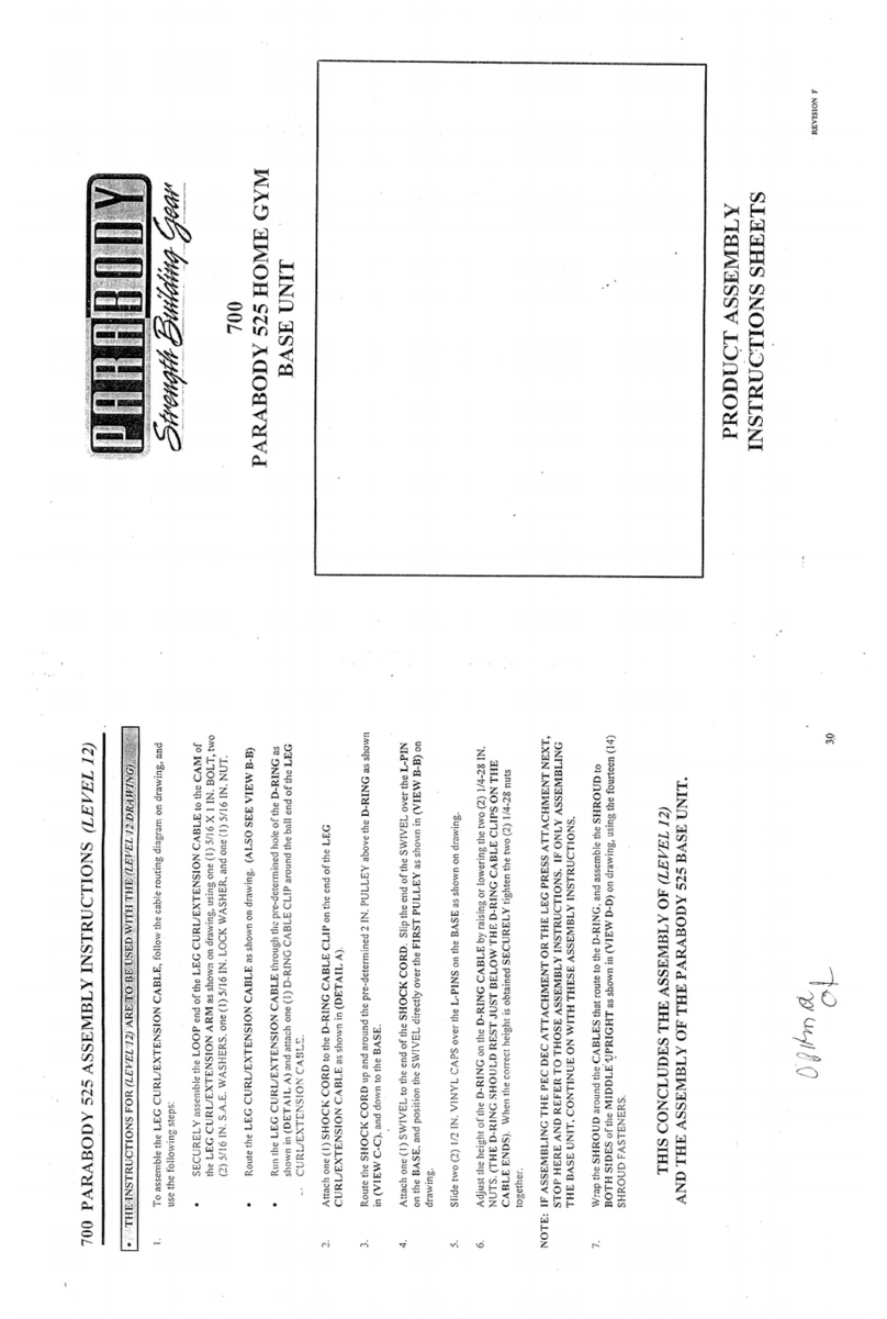
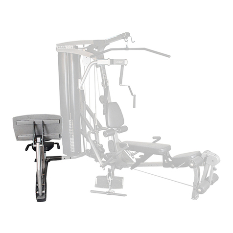
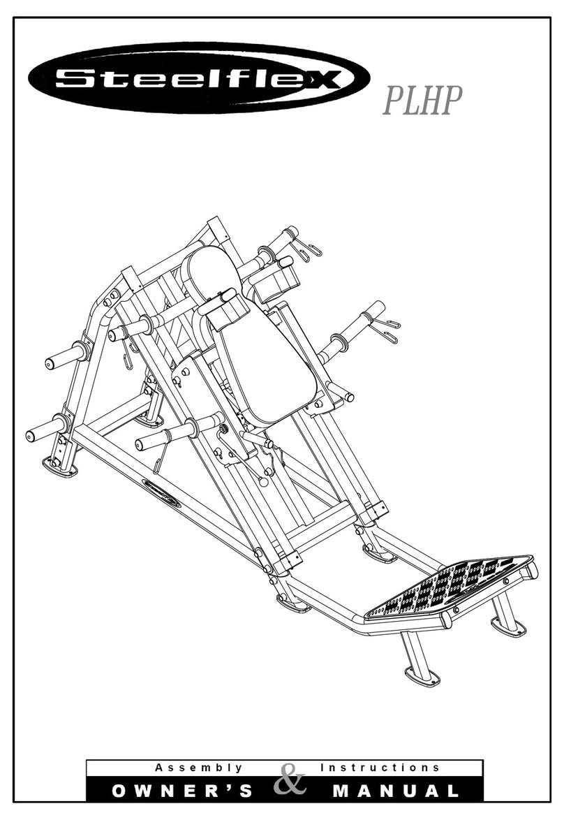
835101 HIP SLED ASSEMBLY INSTRUCTIONS
Pull back the SPRINGPIN on the PLATFORMSLEEVEand insert the PLATFORMADJUSTMENT
into it. Slide the PLATFORMADJUSTMENTdownto the first adjustment hole and release the SPRING
PIN.
Assemble the PLATFORMADJUSTMENTto the PLATFORMas shown on drawing using one (1) 1/2
X 4 IN. BOLT, and one (1) 1/2 IN. LOCKNUT. (TIGHTENTHECONNECTIONENOUGH
REMOVETHE PLAY, YET ALLOWING THE PLATFORM ADJUSTMENT TO ROTATE
FREELY)
SECURELYassemble the LEFTand RIGHTHANDLESto the BASEon tkeir respective sides as shown
on drawing using four (4) 3/8 X 3 IN. BOLTS,eight (8) 3/8 IN. WASHERS,and four (4) 3/8 IN.
NUTS.
10. Slide two (2) 1 X 5 IN. GRIPSover the ends of the LEFTand RIGHTHANDLESas shownon drawing.
11. Place two (2) 2 IN. SQ. COVERCAPSon each end of the base 0fthe REARUPRIGHT.
12.
13.
14.
15.
16.
17.
18.
19.
20.
SECURELYassemble the REARUPRIGHTto the BASEWELDMENTas shown on drawing using
two (2) 1/2 X3-1/4 IN. BOLTS,four (4) 1/2 IN. WASHERS,and two (2) 1/2 IN. LOCK
LOOSELYassemble the LEFTand RIGHTRAILS, along with the SEATPADto the BASE
WELDMENTas shown on drawing using two (2) 3/8 X 4-1/2 IN. BOLTS,two (2) 3/8 IN.
WASHERS,and two (2) 3/8 IN. WASHERS.Temporarily assemble the RAII,S to the REARUPRIGHT
using two (2)1/2 X4-1/2 IN. BOLTSto aid in the assemblyof this step.
Insert four (4) 2 IN. SQ.ENDCAPSinto the each end of the CARRIAGEas shownon drawing.
SECURELYassemble four (4) 3 IN. DIA. WHEELSto the sides of the CARRIAGEas shown
drawingusing four (4) 1/2 X4-1/2 IN. BOLTS,eight (8) 1/2 IN. WASHERS,and four (4) 1/2 IN.
HEIGHT LOCKNUTS.
SECURELYassemble two (2) 2 IN. DIA. WHEELSto the BRACKETSon the left side of the
CARRIAGEas shown on drawing using two (2) 3/8 X 2 IN. BOLTS,four (4) 3/8 IN. WASHERS,
two (2) 3/8 IN. LOCKNUTS.
Assemble the two (2) ADJ. WHEELBRACKETSto the right side of the CARRIAGEas shown
drawing using two (2) I/2 X 2-3/4 IN. BOLTS,two (2) 1/2 IN. WASHERS,and two (2) 1/2 IN.
HEIGHT LOCK ~UTS. (NOTE: TIGHTEN BRACKETS SECURELY TO THE CARRIAGE, THEN
BACKNUT OFF’l/2 TURNTO ALLOWFOR ADJUSTMENTIN A LA’fTER STEP)
SECURELYassemble two (2) 2 IN. DIA. WHEELSto the ADJ. WHEELBRACKETSon the right side
of the CARRIAGEas shownon drawing using two (2) 3/8 X 2 IN. BOLTS,four (4) 3/8 IN. WASHERS,
and two (2) 3/8 IN. LOCKNUTS.
Attach one (1) 4 X 14 IN. NONSKIDSTRIP to the HORIZONTALTUBEof the CARRIAGEas shown
on drawing.
Removethe two temporary 1/2 X 4-1/2 IN. BOLTSfrom (STEP13). Swing the LEFTand RIGHT
RAILSout enough to insert the CARRIAGEASSEMBLYin between them. Allow the CARRIAGEto
rest on the SAFETYSTOPSunderneath the RAILS. SECURELYassemble the RAILSto the REAR
UPRIGHTas shownon drawing, using the two (2) 1/2 X 4-1/2 IN. BOLTS,foyer (4) 1/2 IN. WASHI~RS,
and two (2) 1/2 IN. LOCKNUTS.
5
10/09/95
