manuals.online logo
Brands
  1. Home
  2. •
  3. Brands
  4. •
  5. Paradox
  6. •
  7. Security Sensor
  8. •
  9. Paradox EB-N94 User manual

Paradox EB-N94 User manual

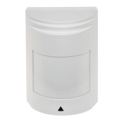
INSTALLATION GUIDE OF EB-N94 FOUR-ELEMENT
INTELLIGENT PIR INTRUSION DETECTOR
Lens
Walk-test LED
PIR
LED
Code switch
Sensitivity adjust
Figure 1.General View Figure 2.Inside View
2.Specifications
Top view
Side view
Connect terminals
Models: EB-N94
Input Voltage 9-16VDC
Cyrrent Drain 30mA@ 12VDC
Detection Range 11.6m*11.6m
Alarm output NC.>100mA/28VDC
Anti white lightresistance
>1000000LUX
Installation height:2m-2.7m
Tamper switch NC.100mA/28VDC
PIR Section:Lens Date
NO.of Curtain Beams (11+11+9)*2=62
Tripping Indication:
lndicator lights forabout 10-30 seconds
Anti -EMI/RFI 10V/m 10MHz-1000MHz
Motion test 0.2m/s-3.5m/s(0.6ft-11ft)
Humidity 5%-95% RH
Accessories:
BR-1:Surface mounted swivelbracket,adjustable 30
down and 45 left/right.
Environmental:
Operating Temp: -10 C to 50 C(14 F to 122 F )
Storage Temp :-20 C to 60 C (-4 F to 40 F)
Physical
Size(H*W*D):176*85*69mm
3.Installation
3.1 General Guidelines
No direct facingcold
/hot source
No direct sunshine Keep away fromhigh
pressure power
No facing metalwall Installation base
should be stable
1.Brief Introduction
EB-N94 is a kind of PIR intrusion detector integrating the most
advanced security technology. It adopts 2 dual PIR sensors with
high accuracy, intelligent digi-tal chip, advanced ,<True Motion
Recognition & Anti-pests>of tware technology,which can help
it to make an accurate judgment of trueintruder or other interfer
-ence that can cause wrong alarm. And it is with function of auto
-matic memory of environmental change, which can avoid wro
-ng alarm a used by hot & cold air, opera-tion machine interfere
-nce. It can prevent effectively the interference cause by a 25 kg
past or 10 cats, insect, mouse, birds etc. Its super filter can be
used indoor and outdoor. This has clear various interference
that com-mon PIR detector can't overcome; and put an end to
wrong alarm and miss alarm .EB-N94 has two different working
modes: bus mode and relay mode, can be used for all kinds of
control panels on the market.
This device iscoherent to Europeparliament direct 1999/5/EC
necessary items andrules, and alsocoherent to the main spirits
th
of radio andtelecomterminal equipmentson March 9 . 1999.
The device alsoreaches the Canadian standard RSS-210. Itcan
be used indoorand outdoor, whichcan reach itsmaximum prote-
ction and avoidanceof above interference.
3. 2Anti-pests installation
The upper partof the
detection area isnon
anti-pests area
Never face thedetector to
the place thatpests can
climb up directly
20KgAnti-pests weight The installation height
of the detectoris 2.2-2.4
meters canAnti-pests
Wall mounting
holes
Cable hole
Bracket mounting
holes
3.3Illustrated Installation Procedure
1 Open holes on base:
A.Mask the drilling
porints and drill in the
the wall.
B.Route the cables
into the base via the
rear channel.
C.Insert two nails and
arrach the base to the
wall with two screws.
D.Insert the bottom
edge of the large PCB
under this tab&press
the top edge in.
3 function of coding switch:
Corner mounting
holes
EB-N94 has two different working modes:bus mode and relay mode,the mode choosing
can be conducted by DIP switch.
4 Setting of coding switch:
Relay mode the switch 1 of DIP=OFF
When setting to the relay mode EB-N94 transmits alarm and temper signal by relay as stan-
dard sensors, same as the figure, can be powered by contacted the power of panel and the
"RED","BLK" of the sensor,"GRN","YEL" unused, on relay mode, the setting only can
be amended by DIP switch and trim pot-ntiometer
Bus mode the switch 1 of DIP=ON
When setting to bus mode EB-N94 transmits alarm, tamper signals and datas by bus,and set-
ting the sensor as well. On bus mode, EB-N94 can be directly connected with control panel. sa-
me as the figure, can be pow-red by contacted the power of panel and the "RED","BLK" of
the sens-r,"GRN","YEL" connected with the correspondance terminals. On bus m-de,the set-
ting can be amended by DIP switch and trim potentiometer, also can by system keypad(shou-
ld be compated with system)get into programming mode.
Single or dual edge processing
This setting direct the DSP digital signal process working mode.Single side mode
is used the normal situation few of interference. Both sides process(out/in analysis)
mode can effectively reduce fault alarm. So, we recommend use this working mode
when the sensor in stallated near interfere resource.
LED setting
LED light 5 second when detected the energy of the moving signal can result alarm enough,
when the energy of the signal not enough, LED blink.
NC
COM
Tamper
Alarm output
Power
EB-N94 PCB
RED BLK GRN YEL TMP TMP
Communicate
bus
GRN
AUX+
AUX-
YEL
ZONE 24H/ZONE
When relay mode,
these two wires not
connect
5 Sensitivity adjustment:
The trim potentiometer will turn bigger when turn clockwise, reverse result
when turn counter-colockwise 0.25s-2s
7. Motion testto protected area
The best operationheight of
EB-N94is 2.1 meter, a little
higher or lowerisalso permitted.
Confirm the adjustableheight
mark on theright ups ide on c ove r
tally withthe installation height.
If another installationheight is
needed, readjust thePCB in
accordance with yourneeds.
Motion test isnecessarily
required inthe protection area in
order to confirmthat areas need
pro-tection arewithin the prote
ctive area.
6. PCB height setting
A. Install the cover, close the fastening position.
Guarantee that the front and back cover close
Tightly without any space or the looseness of
anti-water cover can't prevent humidity entering
into the parts.
B. Crossing to any directionof the detectionarea,
your walking will cause theLED indicator to
lightfor2-3seconds (refer tothe right diagram)
C. Perform motiontest from contrarydirections
in order toconfirm the boundaryof two sides.
Make c onfi rmed that detection centerpointing to
the center ofprotected area.
Contral panel
2 Wire upthe terminal block
Function
Bus mode
Relay mode
Work mode
Digital signal process
LED
Tamper confirm
Invalid
Valid
Invalid
Valid
Invalid
Valid
Single side
Both sides
Relay
Bus
Unused
Unused
DIP switch1=OFF
DIP switch1=ON
DIP switch2=OFF
DIP switch2=ON
DIP switch3=ON
DIP switch3=OFF
Unused
Unused
Unused
Unused
001 1 =OFF
001 1 =ON
001 2 =OFF
001 2 =ON
001 3 =OFF
001 3 =ON
001 5 =ON
001 5 =OFF
002 001=010
Trim potentiometer 0 10
Sensitivity
Moving signal instruct
Even the most sophistic ated detcetors can some times be defeated or may fail towarn due to :DC power failure/improper connection, malicious masking
of thelens,tampering with the optical system, decreased sensitivity in ambient temperatures near that of the human bodyand unexpected failureof a
component part. The above list includesthe most commonreasons for failurerecommended that thedetectorand the entire alarm system be checked
weekly, toensure proper performance.An alarm system should not be regarded asa substitute forinsurance. Home & property owners or renters shou ldbe
prudent enough tocontinue insuring theirlives & property, even thoughthey are protectedby an alarmsystem.
WARNING!Changes or modificationsto this unitnot expressly approved by the partyresponsible for compliancecould
void the users authority tooperate the equipment.
This device hasbeen tested andfound to complywith the limitsfor a ClassB digitaldevice, pursuant harmful interferencein residential installations .This equipment
generates,us es and can radiate radio frequen cy energy and ,if not installed and used in accordance withthe ins-tructions ,may cause harmful in-terference to radioand
televisionreception.However,there is noguaranteethat interferencewill not occur in aparticular installation .If thisdevice does causesuch interference ,which can be verfied
by turning thedevice off andon ,the useris encouraged to eliminatethe interference by oneor moreof the followingmeasures:
4.Special comments
P/N 20605002A00


Other Paradox Security Sensor manuals

Paradox SR230 User manual

Paradox

Paradox SR230 User manual

Paradox NV780MX User manual

Paradox

Paradox NV780MX User manual

Paradox NV35MR User manual

Paradox

Paradox NV35MR User manual

Paradox DCT6 User manual

Paradox

Paradox DCT6 User manual

Paradox PMD75N User manual

Paradox

Paradox PMD75N User manual

Paradox NV75MW User manual

Paradox

Paradox NV75MW User manual

Paradox NV35MX User manual

Paradox

Paradox NV35MX User manual

Paradox ENVY NVX80 User manual

Paradox

Paradox ENVY NVX80 User manual

Paradox Digigard DG75 User manual

Paradox

Paradox Digigard DG75 User manual

Paradox NV37M User manual

Paradox

Paradox NV37M User manual

Paradox PMD85 User manual

Paradox

Paradox PMD85 User manual

Paradox SR250 User manual

Paradox

Paradox SR250 User manual

Paradox NV35MR User manual

Paradox

Paradox NV35MR User manual

Paradox SR230 User manual

Paradox

Paradox SR230 User manual

Paradox DG457 User manual

Paradox

Paradox DG457 User manual

Paradox Digigard DG85 User manual

Paradox

Paradox Digigard DG85 User manual

Paradox Magellan PMD1P User manual

Paradox

Paradox Magellan PMD1P User manual

Paradox Magellan PMD75 User manual

Paradox

Paradox Magellan PMD75 User manual

Paradox WD1 User manual

Paradox

Paradox WD1 User manual

Paradox Digigard DG85 User manual

Paradox

Paradox Digigard DG85 User manual

Paradox PMD85 User manual

Paradox

Paradox PMD85 User manual

Paradox PMD2P User manual

Paradox

Paradox PMD2P User manual

Paradox NV780MX User manual

Paradox

Paradox NV780MX User manual

Paradox MAGELLAN MG-PMD75 User manual

Paradox

Paradox MAGELLAN MG-PMD75 User manual

Popular Security Sensor manuals by other brands

hyfire ALTAIR HFI-MA-05 quick start guide

hyfire

hyfire ALTAIR HFI-MA-05 quick start guide

Macurco OX-6 User instructions

Macurco

Macurco OX-6 User instructions

AVE LUCE AMICA instruction manual

AVE

AVE LUCE AMICA instruction manual

Reer EOS2 Installation, use and maintenance

Reer

Reer EOS2 Installation, use and maintenance

DBI SALA Hot Work NANO-LOK SRL Series instruction manual

DBI SALA

DBI SALA Hot Work NANO-LOK SRL Series instruction manual

ELRO ES360M user manual

ELRO

ELRO ES360M user manual

AVS Electronics JET DT WS 4 manual

AVS Electronics

AVS Electronics JET DT WS 4 manual

Cabletech URZ0420 owner's manual

Cabletech

Cabletech URZ0420 owner's manual

Sunx NA1-11 instruction manual

Sunx

Sunx NA1-11 instruction manual

NookBox SVGS-1 installation guide

NookBox

NookBox SVGS-1 installation guide

Datasensing S3N-PR T5 Series manual

Datasensing

Datasensing S3N-PR T5 Series manual

Satel AQUA manual

Satel

Satel AQUA manual

Orbis EBR-2 Instructions for use

Orbis

Orbis EBR-2 Instructions for use

BabySense 7 user guide

BabySense

BabySense 7 user guide

Agilent Technologies 5977C Series operating manual

Agilent Technologies

Agilent Technologies 5977C Series operating manual

IFM OJ50 laser Series operating instructions

IFM

IFM OJ50 laser Series operating instructions

Newlec EMERGENCY TWINSPOT instructions

Newlec

Newlec EMERGENCY TWINSPOT instructions

CST/BERGER Magna-Trak Series Original instructions

CST/BERGER

CST/BERGER Magna-Trak Series Original instructions

manuals.online logo
manuals.online logoBrands
  • About & Mission
  • Contact us
  • Privacy Policy
  • Terms and Conditions

Copyright 2025 Manuals.Online. All Rights Reserved.