manuals.online logo
Brands
  1. Home
  2. •
  3. Brands
  4. •
  5. Parker
  6. •
  7. Control Unit
  8. •
  9. Parker 89-00B Guide

Parker 89-00B Guide

1
Refrigerating Specialties Division
BULLETIN 89-00B
March 2007
Installation, Service and Parts Information
ISO 9001 CERTIFIED
310826
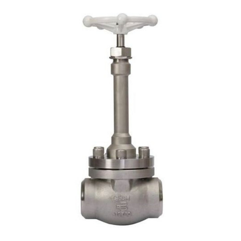
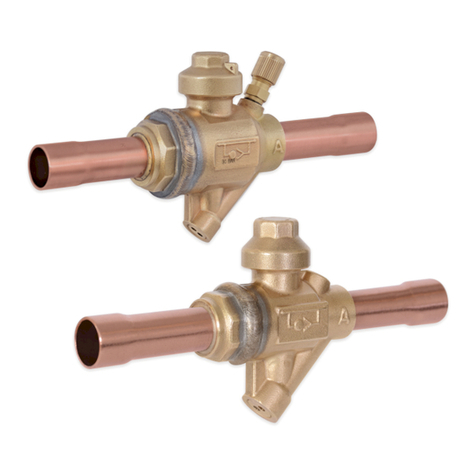
Liquid Drain Ball Valves
Sizes 1/2”, 3/4” & 1” (13, 20 & 25mm)
Suitable For Ammonia, Flurocarbons,
Nitrogen and Carbon Dioxide
Features
• Spring Return to Close
• Ball is Relief Ported
• RPTFE Stuffing Box Ring
• All Components of Lever are Stainless
Steel
• Blow-out Proof Stem Design
• Adjustable Packing Gland
Pressure Relief
Determine and provide corrective action against excessive
pressure build up in the valve or piping system due
to thermal expansion. Thermal expansion can create
extreme pressures well above the working pressure
limit of the valve which can cause leaking or bursting of
the valve
Supports
If you choose to connect a flexible hose or other non-ridged
conduit to the valve, the design of such installation must
prevent any “whipping action” that could injure or damage
personnel or equipment. Valve must be immobile.
Fittings
Use only those fittings or piping that are compatible
with the valves being used to prevent breakage and/or
leakage.
Pressure/Temperature Limits
The maximum working pressure limit of the valve is
marked on the valve body. Never exceed the “WOG” rating
which is specified up to 100°F. Temperatures higher than
100°F decrease the maximum working pressure limit.
Installation
The use of ptfe pipe tape as a sealant is recommended for
threaded valves when making joints. Correct lubrication
of stainless steel pipe threads is especially important
to prevent thread galling. Do not apply excessive torque
when installing the valve. To prevent distortion or damage
to the valve, do not apply torque through the valve. Use
proper supports in handling prefabricated sections and
in final installations. Always test the system before
using.
Maintenance
Do not disassemble the valve while under pressure.
Request a maintenance manual before attempting repairs
to the valve.
Refrigerating Specialties Division 2
Warranty
All Refrigerating Specialties products are warranted against
defects in workmanship and materials for a period of one
year from date of shipment from originating factory. This
warranty is in force only when products are properly installed,
field assembled, maintained, and operated in use and service
as specifically stated in Refrigerating Specialties Catalogs
or Bulletins for normal refrigeration applications, unless
otherwise approved in writing by Refrigerating Specialties
Division. Defective products, or parts thereof, returned to the
factory with transportation charges prepaid and found to be
defective by factory inspection will be replaced or repaired at
Refrigerating Specialties option, free of charge F.O.B. factory.
Warranty does not cover products that have been altered, or
repaired in the field; damaged in transit, accidents, misuse, or
abuse. Products disabled by dirt or other foreign substances
will not be considered defective.
The express warranty above constitutes the only warranty of
Refrigerating Specialties products, and is in lieu of all other
warranties, expressed or implied, written or oral, including
any warranty of merchantability or warranty of fitness for a
particular purpose and in no event is Refrigerating Specialties
responsible for any consequential damages of any nature
whatsoever. No employee, agent, dealer or other person is
authorized to give any warranties on behalf of Refrigerating
Specialties nor to assume for Refrigerating Specialties any other
liability in connection with any of it products.
Safe Operation (See also Bulletin RSB)
People doing any work on a refrigeration system must be
qualified and completely familiar with the system and the
Refrigerating Specialties Division valves involved, or all
other precautions will be meaningless. This includes read-
ing and understanding pertinent Refrigerating Specialties
Division product Bulletins and Safety Bulletin RSB prior to
installation or servicing work.
Where cold refrigerant liquid lines are used, it is necessary that
certain precautions be taken to avoid damage that could result
from liquid expansion. Temperature increase in a piping section
full of solid liquid will cause high pressure due to the expanding
liquid that can possibly rupture a gasket, pipe or valve. All hand
valves isolating such sections should be marked, warning
against accidental closing, and must not be closed until the liquid
is removed. Check valves must never be installed upstream of
solenoid valves, or regulators with electric shut-off, nor should
hand valve upstream of solenoid valves or downstream of check
valves be close until the liquid has been removed. It is advisable
to properly install relief devices in any section where liquid
expansion could take place.
Avoid all piping or control arrangements that might produce
thermal or pressure shock. For the protection of people and
products, all refrigerant must be removed from the section to
be worked on before a valve, strainer, or other device is opened
or removed. Flanges with ODS connections are not suitable for
ammonia service.
Carbon Steel Stainless Steel
Part # Part # kg lb
1/2" 206548 206551 0.6 1.3
3/4" 206549 206552 0.9 2
1" 206550 206553 1 2.3
Liquid Drain Ball Valve
Shipping Weights
Size
mm inch mm inch mm inch mm inch
1/2" 12.7 0.5 28 1.12 57 2.25 178 7.00
3/4" 17 0.68 38 1.5 76 3.00 178 7.00
1" 22 0.87 43 1.68 86 3.37 178 7.00
A
B
C
D
Size
2445 S. 25th Ave. Broadview Ill 60155
T 708-681-6300 F 708-681-6306
Other Parker Control Unit manuals

Parker D1FB EE Series User manual

Parker

Parker D1FB EE Series User manual

Parker PSUP Series User manual

Parker

Parker PSUP Series User manual

Parker IQAN-LC5-C02 User manual

Parker

Parker IQAN-LC5-C02 User manual

Parker PHD Series User manual

Parker

Parker PHD Series User manual

Parker P6 Technical specifications

Parker

Parker P6 Technical specifications

Parker PSSTACM12A Installation and maintenance instructions

Parker

Parker PSSTACM12A Installation and maintenance instructions

Parker GC Series User guide

Parker

Parker GC Series User guide

Parker D1FH series User manual

Parker

Parker D1FH series User manual

Parker TPQ Series User manual

Parker

Parker TPQ Series User manual

Parker PEV Service manual

Parker

Parker PEV Service manual

Parker PACHC Series User manual

Parker

Parker PACHC Series User manual

Parker U Series Technical specifications

Parker

Parker U Series Technical specifications

Parker Series DFplus User manual

Parker

Parker Series DFplus User manual

Parker EP Series Pro-Bloc User manual

Parker

Parker EP Series Pro-Bloc User manual

Parker R4V Series Wiring diagram

Parker

Parker R4V Series Wiring diagram

Parker TDC Series User manual

Parker

Parker TDC Series User manual

Parker HASV08R User manual

Parker

Parker HASV08R User manual

Parker Racor 200 Series User manual

Parker

Parker Racor 200 Series User manual

Parker RE06M T Series User manual

Parker

Parker RE06M T Series User manual

Parker SciLog DINCon Assembly instructions

Parker

Parker SciLog DINCon Assembly instructions

Parker D1FV EE Series User manual

Parker

Parker D1FV EE Series User manual

Parker CK1-DN User manual

Parker

Parker CK1-DN User manual

Parker Sporlan SD-114 User guide

Parker

Parker Sporlan SD-114 User guide

Parker PSST8M23A Installation and maintenance instructions

Parker

Parker PSST8M23A Installation and maintenance instructions

Popular Control Unit manuals by other brands

System air Topvex Series installation manual

System air

System air Topvex Series installation manual

Siemens 3VT9500-6AE00 operating instructions

Siemens

Siemens 3VT9500-6AE00 operating instructions

WURM DOC-XP quick start guide

WURM

WURM DOC-XP quick start guide

Siemens SIRIUS 3RU Series manual

Siemens

Siemens SIRIUS 3RU Series manual

Master X60 EGO user manual

Master

Master X60 EGO user manual

EOS EmoTouch 3 Installation and operation manual

EOS

EOS EmoTouch 3 Installation and operation manual

Sirca TRUNNION S30T Series Installation, use and maintenance

Sirca

Sirca TRUNNION S30T Series Installation, use and maintenance

WEG SSW900-CETH-IP-N Installation, configuration and operations guide

WEG

WEG SSW900-CETH-IP-N Installation, configuration and operations guide

Henco HencoLogic CU-WIFIRF Quick installation guide

Henco

Henco HencoLogic CU-WIFIRF Quick installation guide

Honeywell L6190A instruction sheet

Honeywell

Honeywell L6190A instruction sheet

Jomox T-RACKONIZER manual

Jomox

Jomox T-RACKONIZER manual

Sit 630 Eurosit Use and Installation Instructions

Sit

Sit 630 Eurosit Use and Installation Instructions

A.R.I. Eliptix R-30RM Installation, operation and maintenance

A.R.I.

A.R.I. Eliptix R-30RM Installation, operation and maintenance

GEM 4221 Installation, operating and maintenance instructions

GEM

GEM 4221 Installation, operating and maintenance instructions

Becker Centronic UnitControl UC520 Assembly and operating instructions

Becker

Becker Centronic UnitControl UC520 Assembly and operating instructions

OWI CCRC-403 Specifications

OWI

OWI CCRC-403 Specifications

HP A12500 Product End-of-Life Disassembly Instructions

HP

HP A12500 Product End-of-Life Disassembly Instructions

Sollae Systems EZL-90 manual

Sollae Systems

Sollae Systems EZL-90 manual

manuals.online logo
manuals.online logoBrands
  • About & Mission
  • Contact us
  • Privacy Policy
  • Terms and Conditions

Copyright 2025 Manuals.Online. All Rights Reserved.