Via Mecenate, 90 - 20138 MILANO - ITALIA
TEL. +39-02-580 77 1 (15 linee r.a.)
FAX +39-02-580 77 277
http://www.paso.it
Printed in Italy - 07/00 - 2K - 11/412-B
S.p.A
NOTA
Nel continuo intento di migliorare i propri prodotti, la PASO S.p.A. si
riserva il diritto di apportare modifiche ai disegni e alle caratteristiche
tecniche in qualsiasi momento e senza alcun preavviso.
NOTE
PASO S.p.A. strive to improve their products continuously, and therefore
reserve the right to make changes to the drawings and technical
specifications at any time and without notice.
NOTE
En raison de lamélioration constante de ses produits, PASO S.p.A. se
réserve le droit dapporter des modifications aux dessins et caractéristiques
techniques à tout instant et sans aucun préavis.
MERKE
In der Überzeugung, die eigenen Produkte beständig verbessern zu wollen,
behält sich PASO S.p.A. das Recht vor, jederzeit und ohne Vorankündigung
Änderungen an technischen Zeichnungen und - Merkmalen vorzunehmem.
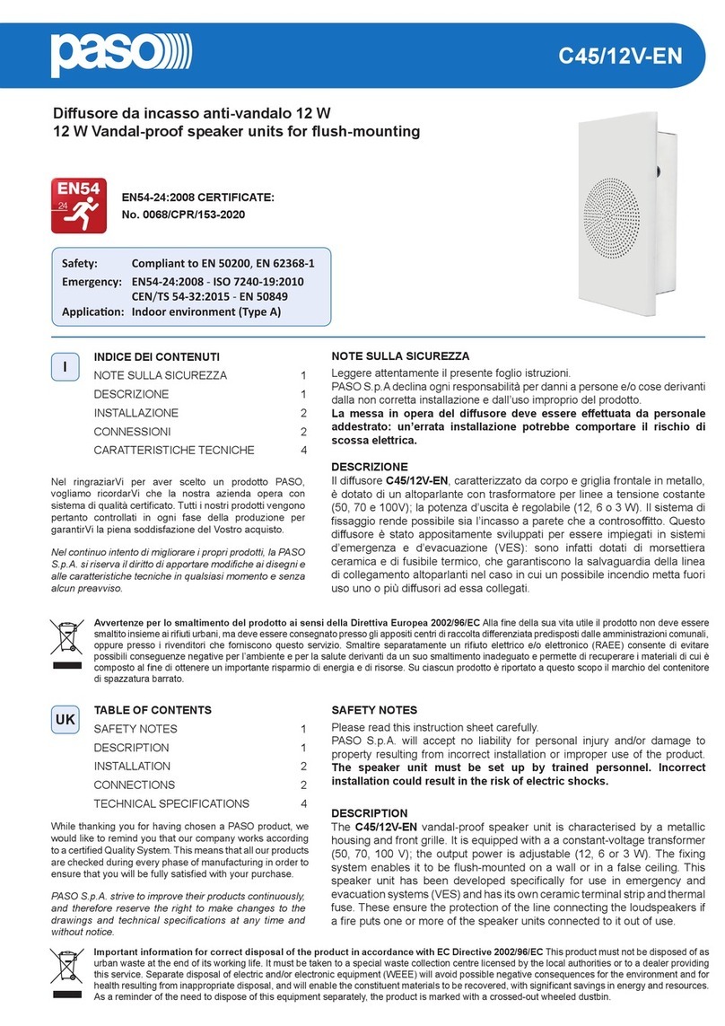
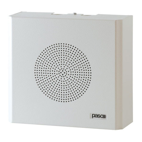
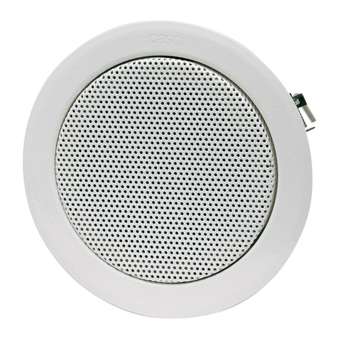
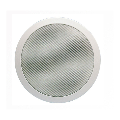
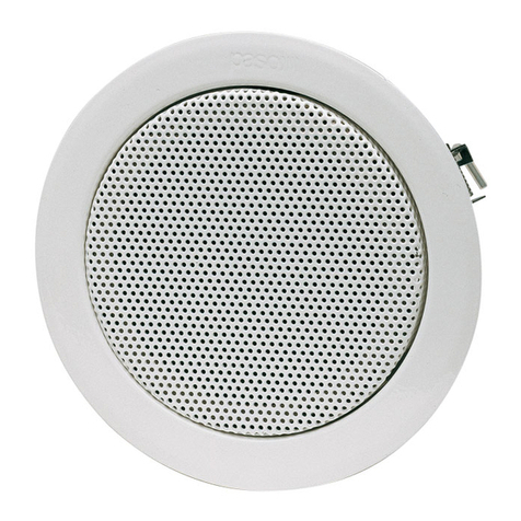
C57-T, C58/6-T, C58/12-T
Modello TM* AT*
Model
C57-T TM99 AT73
C58/6-T TM99 AT72
C58/12-T TM108 AT72
DESCRIZIONE GENERALE
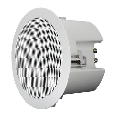
Le plafoniere C57-T, C58/6-T e C58/12-T sono realizzate completamente
in metallo; ciò le rende particolarmente robuste ed affidabili nel tempo.
Il sistema di fissaggio a molle ed il montaggio a baionetta riducono
notevolmente i tempi di installazione.
Utilizzando le calotte antifiamma accessorie AC907 e AC908, le plafoniere
rispondono alle norme di sicurezza contro gli incendi.
Le plafoniere sono composte da due parti: il corpo principale, che supporta
l'altoparlante ed il traslatore di linea, e l'anello di sostegno.
COLLEGAMENTI
I collegamenti devono essere realizzati con linea di distribuzione a tensione
costante; per le connessioni è disponibile una morsettiera alle terminazioni
del traslatore di linea.
Riferirsi alle relative tabelle (pag. 4) per i valori di potenza impiegati.
Plafoniere metalliche
Metal ceiling speakers
Plafonniers metalliques
Metall-Deckenlautsprecher
Istruzioni di installazione e montaggio
Instructions for installation and mounting
Instruction d'installation et de montage
Montage- und Installationsanleitung
INDICE
Descrizione generale................................................................... 1
Collegamenti ............................................................................... 1
Istruzioni di montaggio ................................................................ 2
Dima di foratura ...................................................................... 2/3
Schema collegamenti................................................................... 4
Dati tecnici.................................................................................. 4
TABLE OF CONTENTS
General description ..................................................................... 1
Connections ............................................................................... 1
Mounting instructions .................................................................. 2
Perforation template................................................................ 2/3
Connections diagram .................................................................. 4
Technical data ............................................................................. 4
SOMMAIRE
Description générale ................................................................... 1
Connexions ................................................................................ 1
Instructions de montage ............................................................. 2
Répere de perforation ............................................................. 2/3
Schèma de connexions ............................................................... 4
Données techniques ................................................................... 4
INHALTSGABE
Allgemeine Beschreibung ............................................................. 1
Anschlüsse ................................................................................. 1
Montagesanleitung ..................................................................... 2
Schablone ............................................................................... 2/3
Anschlüßschema ......................................................................... 4
Technische Daten ....................................................................... 4
DESCRIPTION GENERALE
Les plafonniers C57-T, C58/6-T et C58/12-T sont entièrement
métalliques, ce qui les rend extrêmement robustes et fiables dans le temps.
Le système de fixation à ressorts et le montage à baïonnette réduisent
considérablement les temps d'installation.
Avec lutilisation des accessoires AC907 et AC908, calottes antiflamme,
les plafonniers répondent aux normes de sécurité en matière dincendie.
Les plafonniers sont composés de deux parties: le corps principal (support
du haut-parleur) et la bague de soutien.
CONNEXIONS
Les connexions doivent être effectuées sur la ligne de distribution à
tension constante; la barrette de raccordement à relie les différentes
bornes du translateur de ligne. En ce qui concerne les valeurs de puissance
employées voir les tableau correspondants (page 4).
ALLGEMEINE BESCHREIBUNG
Die Deckenlautsprecher C57-T, C58/6-T und C58/12-T sind vollständig
aus Metall hergestellt; dies macht sie besonders stabil und zuverlässig.
Das Befestigungssystem mit Federn und die Bajonettmontage reduziert die
Einbauzeiten erheblich; durch Verwendung der flammwidrigen Kappen,
Zubehörteile AC907 und AC908, entsprechen die Deckenlautsprecher
den Brandverhütungsvorschriften.
Die Deckenlautsprecher bestehen aus zwei Teilen: dem Korb mit dem
Lautsprecher und den Anschlussklemmen und dem Haltering.
ANSCHLÜSSE
Für die Anschlüsse steht ein Klemmenbrett zur Verfügung.
Was die verwendeten Leistungswerte betrifft, ist auf die Tabellen (Seite 4)
Bezug zu nehmen.
GENERAL DESCRIPTION
The C57-T, C58/6-T and C58/12-T ceiling speakers are made integrally
of metal, which makes them particularly sturdy and reliable over time.
The spring-type fitting mechanism and the bayonet fitting enormously
reduce installation time.
In order to satisfy fire safety standards, the optional fire domes AC907
and AC908 can be installed.
Ceiling speakers are made up of two parts: the main body (supporting
the loudspeaker) and the mounting ring.
CONNECTIONS
Connections must be made through constant voltage line.
Line translator terminations include a terminal block for connections.
Refer to the appropriate tables (page 4) for the power values used.
Tabella/Table 1
C57-T, C58/6-T
Colore filo
Wire colour
Marrone
Brown
Blu
Blue
Verde
Green
Giallo
Yellow
Rosso
Red
Impedenza
Impedance 6670 Ω3330 Ω1670 Ω815 Ω415 Ω
Tensione
Voltage
Potenza
Power
100 V 1.5 W 3 W 6 W - -
70 V 0.75 W 1.5 W 3 W 6 W -
50 V 0.3 W 0.75 W 1.5 W 3 W 6 W
Comune
Common
Nero
Black
C58/12-T
Colore filo
Wire colour
Marrone
Brown
Blu
Blue
Verde
Green
Giallo
Yellow
Rosso
Red
Impedenza
Impedance 3330 Ω1670 Ω815 Ω415 Ω210 Ω
Tensione
Voltage
Potenza
Power
100 V 3 W 6 W 12 W - -
70 V 1.5 W 3 W 6 W 12 W -
50 V 0.75 W 1.5 W 3 W 6 W 12 W
Comune
Common
Nero
Black
Tabella/Table 2
DATI TECNICI - TECHNICAL DATA - DONNÉES TECHNIQUES - TECHNISCHE DATEN
DATI TECNICI
TECHNICAL DATA C57-T C58/6-T C58/12-T DONNEES TECHNIQUES
TECHNISCHE DATEN
Potenza - Power 6 - 3 - 1,5 W 12 - 6 - 3 W Puissance - Leistung
Tensione di linea - Line voltage 50 - 70 - 100 V Tension de ligne - Konstantspannung
Sensibilità - Sensitivity 95 dB Sensibilité - Empfindlichkeit
Pressione acustica - Acoustic pressure 102 dB 106 dB Pression acoustique - Schalldruck
Risposta in frequenza - Frequency response 100 ÷ 15000 Hz 80 ÷ 20000 Hz Réponse en fréquence - Frequenzgang
Diametro esterno - External diameter 180 mm 220 mm Diamètre extérieur - Außendurchmesser
Foro di montaggio - Mounting hole 160/170 mm
(min/max)
200/210 mm
(min/max) Trou de fixation - Befestigungsöffnung
Ingombro massimo - Overall dimensions 110 mm
(con AC907)
115 mm
(con AC908) Encombrement max. - Einbautiefe
Trasformatore - Transformer TM99 TM108 Transformateur - Transformator
Peso totale - Total weight 1,1 kg 1,3 kg 1,45 kg Poids total - Gesamtgewicht
Ø 180 mm
Ø 220 mm
C58/6-T
C58/12-T
C57-T
14
11-412-B.p65 10/07/00, 10.551
