PBZ CropCare LGX25-2 User manual

by PBZ
25 Gallon Skid Sprayer
Model LGX25-2
Form: LGX25-2OM
Rev. A Date: 10/20
Manufactured by PBZ LLC
A Paul B Zimmerman Inc. Company
www.CropCareEquipment.com
Owner's Manual

2
Table Of Contents
Identication of Machine ...................................................................... 2
Specications............................................................................................. 2
Introduction ............................................................................................... 3
Safety ............................................................................................................ 3
Signal Words.................................................................................... 3
General Guidelines........................................................................ 4
Before Operation ........................................................................... 5
During Operation .......................................................................... 5
Following Operation .................................................................... 5
Pump Safety Precautions............................................................ 5
Installation .................................................................................................. 6
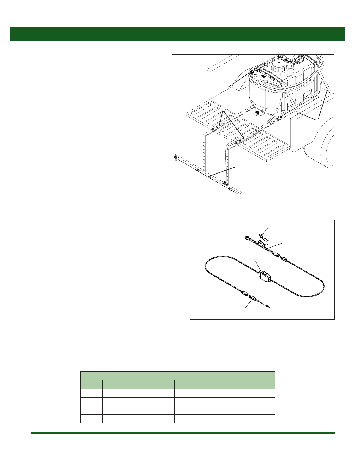
Mounting the Skid Sprayer........................................................ 6
Wiring Harness ............................................................................... 6
Calibrating the Sprayer........................................................................... 7
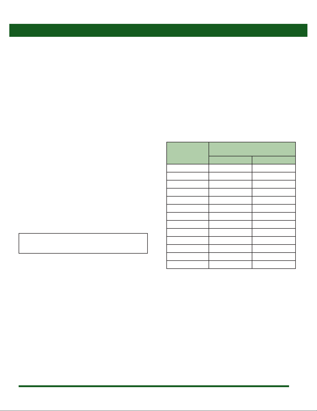
1. Calculating the Speed............................................................. 7
2. Application Rate Charts.......................................................... 8
Boom Application Rate Chart ................................................... 8
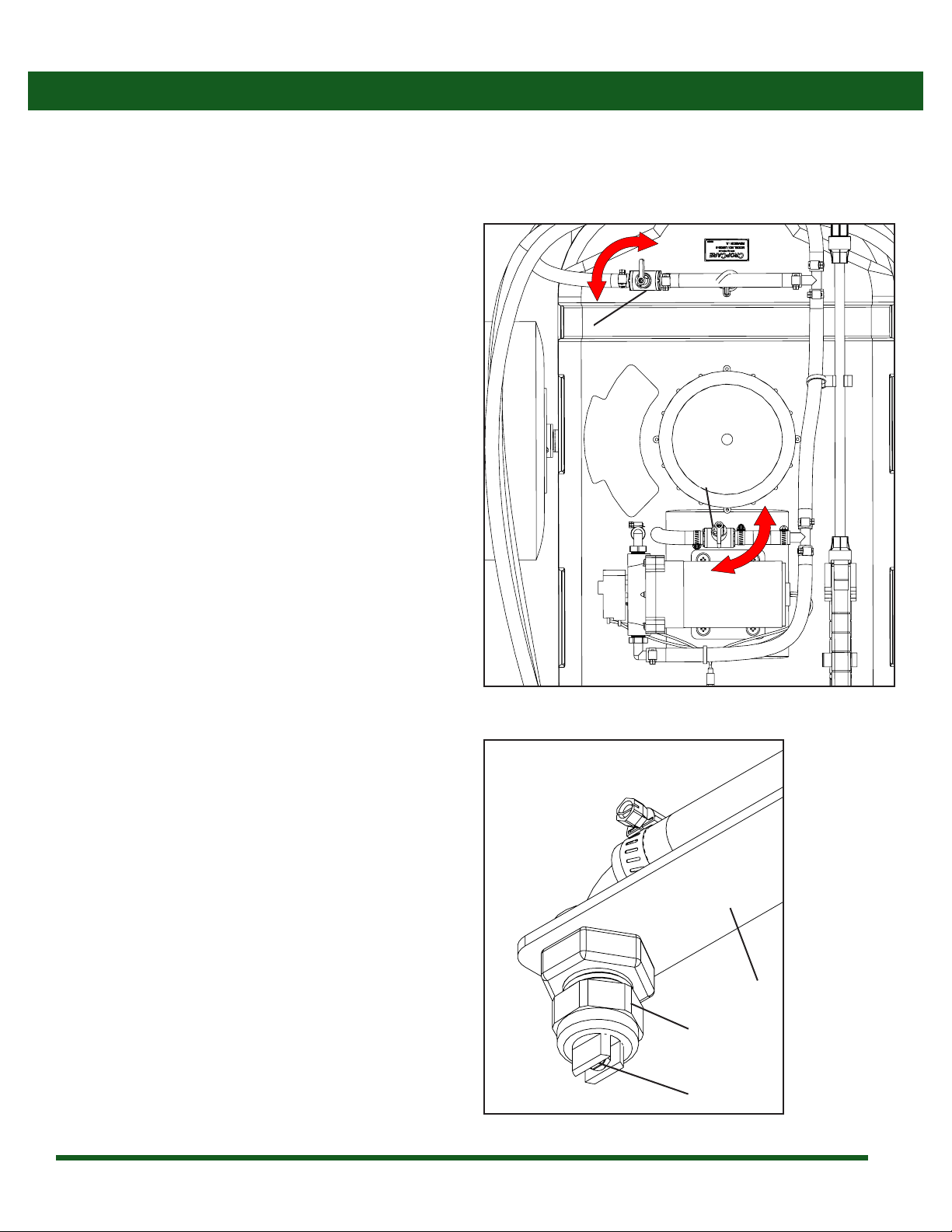
Operating Instructions ........................................................................... 9
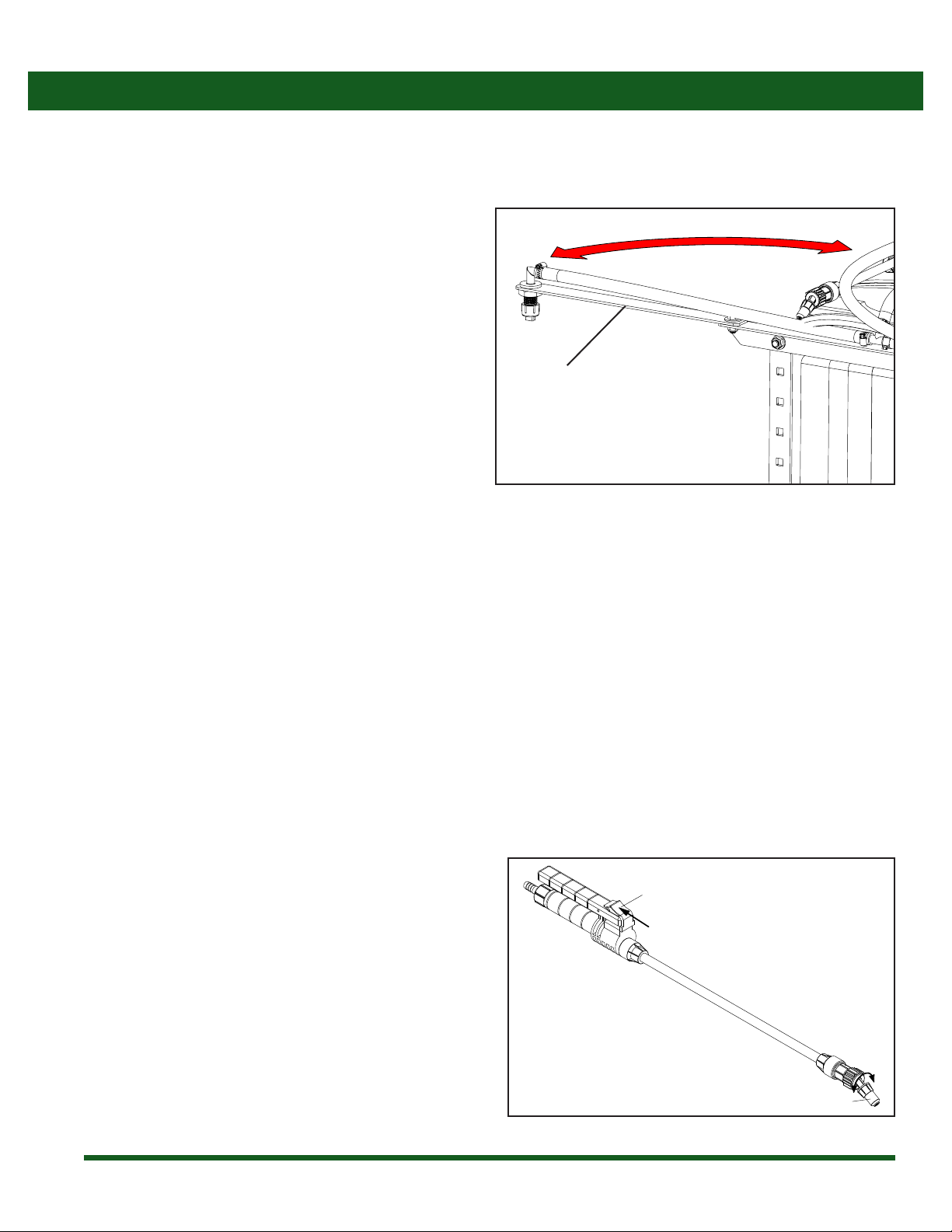
Spraying with the Boom .......................................................9-10
Spraying with the Spray Gun ..................................................10
Following Operation ..................................................................11
Maintenance Instructions ............................................................ 11-12
Routine Maintenance.......................................................... 11-12
Winterizing your Sprayer..........................................................12
Troubleshooting .....................................................................................13
Breakdowns and Parts Lists ......................................................... 14-16
Base Unit Breakdown.................................................................14
Base Unit Parts List......................................................................15
Pump Breakdown & Parts List.................................................16
CropCare® Limited Warranty ..............................................................17
Ordering Parts .........................................................................................17
Specications
Tank capacity ................................................................................ 25 gal
Min power supply ..................................................... 12 volt / 8 amp
Wiring harness length ........................................................................ 8’
Pump:
Type...........................................................................Diaphragm pump
Manufacturer .............................................................................Remco®
Max pressure..................................................................................60 psi
Max ow rate ............................................................................2.2 gpm
Sprayer:
Spraying width (Boom) ...................................................................90”
Hose length (Handgun) ...................................................................15’
25 gallon LGX Skid Sprayer
Weight:
Base unit (empty) .........................................................................40 lbs
Base unit (full).............................................................................250 lbs
Identication of Machine
• Model #’s: LGX25-2
• The model number and revision identication decal is located on top of the tank .

3
Safety
-The safety alert symbol for safety signs & decals that contain one of the three signal words (DANGER, WARNING, & CAUTION)
will appear as shown in Figure 1.
Safety Alert Symbol
Figure 1: Safety Alert Symbol
Signal Words
-There are three signal words; DANGER, WARNING, and CAUTION. The signal words bring attention to the existence and
relative seriousness of a hazard.
• DANGER: The signal word DANGER indicates an imminently hazardous situation which, if not avoided, will result in
death or serious injury
• WARNING: The signal word WARNING indicates a potentially hazardous situation which, if not avoided, could result in
death or serious injury.
• CAUTION: The signal word CAUTION indicates a potentially hazardous situation which, if not avoided, may result in
minor or moderate injury.
Introduction
• Familiarize yourself and other operators with the sprayer’s components and how all parts are operated.
• Read and understand the chemical manufacturer’s labels, warnings, and instructions.
• Know and fulll all state pesticide applicator license requirements.
• Contact your authorized CropCare® Dealer for help interpreting the owners manual.
• Read and follow ALL of the chemical manufacturer’s labels, warnings, and instructions about chemical usage! A material
safety data sheet (MSDS) should be provided by the chemical manufacturer. CropCare®is not liable for misuse or mishandling
of chemicals before spraying, during spraying, and after spraying.
Please read and understand this manual and its instructions and warnings completely before operating the sprayer.

4
Every year many unnecessary accidents occur due to improper equipment handling and a disregard for safety precautions. You, the
operator, can avoid accidents by observing the precautions listed in this section.
General Guidelines
• The operator should be a responsible adult. Do not allow persons to operate this sprayer until they have displayed a thorough
understanding of sprayer safety precautions and operational use!
• All operators must also fulll state pesticide applicator license requirements!
• Never attempt to operate this sprayer when under the inuence of alcohol or drugs.
• The best defense against accidents is a careful and responsible operator.
• A chemical warning decal and an owner's manual warning decal are located on the sprayer’s tank. (Figure 1). Be aware of their
location. Always replace any warning or safety decals that are not legible or are missing.
• When transporting the sprayer on public roads, always follow state and local regulations regarding safety and transportation
requirements. Use the necessary lights and slow moving vehicle (SMV) emblems.
• If there is any portion of this manual that you do not fully understand, please contact the original retailer of this product.
-Additional Signal Words.
• NOTE: The signal word NOTE provides information on operator safety and operator tips.
• IMPORTANT: The signal word IMPORTANT indicates a recommended action or a restriction that will ensure correct
equipment operation and performance.
Safety
Signal Words
Safety
Figure 1: Chemical Warning / Read Owner’s Manual Decal

5
Before Operation
• Carefully study and understand this owner's manual.
• Read and follow chemical manufacturer's labels,
warnings, and instructions! A material safety data
sheet (MSDS) should be provided by the chemical
manufacturer.
• To avoid injury from chemical hazards, wear the proper
protective clothing. Each chemical manufacturer's
clothing requirements are listed under the “Personal
Protective Equipment (PPE)” section in the chemical
instructions.
• Do not wear loose-tting clothing which may catch in
moving parts.
• Never exceed the vehicle manufacturer's load rating.
• Give the sprayer a visual inspection for any worn parts,
loose bolts, or other visible problems, and make the
necessary repairs. See the “Maintenance Instructions”
section for instructions.
• Make sure the area is clear of any people or obstructions
before using the sprayer.
• Have all operators practice operating the sprayer and
its attachments, using clean water only, until all persons
are completely capable of safe operation.
During Operation
• Always be aware of bystanders, particularly children!
Always look before moving the sprayer or the utility
vehicle.
• No passengers are allowed on or in the vehicle or
sprayer at anytime.
• Keep hands and body parts clear of all moving parts.
• Be aware of dangerous terrain such as holes, slopes,
drop-os, banks, rocks, and hidden hazards.
Following Operation
• Operate the vehicle and sprayer up and down slopes,
not across.
• Allow for sprayer boom length when making turns.
• Never leave running equipment unattended!
• Rememberthataccidentscanevenhappentoseasoned
operators. Always take your time and follow all safety
instructions.
• Following operation, stop the vehicle, set brakes, shut
o engine, and remove ignition key.
• Store the sprayer away from human and livestock
activity.
• Park the sprayer on a hard level surface
• Do not permit children to play on or around sprayer.
Pump Safety Precautions
• Never pump ammable or explosive uids such as
gasoline, fuel oil, kerosene, etc.
• NOTE: The pump may be run dry for limited periods of
time without resulting in damage.
• Always disconnect the power to the pump when
working on the pump. Failure to do this could result
in electrical shock.
Safety

6
Wiring Harness
Figure 2: Wiring Harness
1
2
3
4
To Pump Motor
Installation
Wiring Harness
Ref # Qty. Part Number Description
1 1 -- Motor Plug End
2 1 SPT-SWH-9615A-16G Harness, Wiring 8 Ft w/ Switch
3 1 SPT-BCG-1215A-16G Harness, Battery Connector w/15A Fuse
4 1 ATC-15 Fuse, 15 Amp Buss
1. The wiring harness needs to be connected to a DC
power source (vehicle battery) or a power access
point providing at least 12 volts & 10 amps of current
to the ring terminals on the fuse harness (3) (Figure
2). NOTE: Make sure that the selected power source
provides the adequate power requirements as stated
above. Inadequate power can cause problems and
performance issues with the pump.
2. Connect the red wire to the positive terminal on the
vehicle’s battery or other alternate power source
positive terminal. Proceed to connect the black wire
to the negative terminal of the vehicle’s battery or a
good ground source. NOTE: The fused wire harness (3)
(Figure 2) can be unplugged from the switch harness
(2) (Figure 2) and be left attached to the battery or
power source for convenience purposes.
3. Mount the switch (2) (Figure 2) in a location that is easily accessible for operation on the vehicle. Make sure to secure the switch
so that it cannot fall out of place or become entangled and cause damage. NOTE: Use caution when routing the wiring harness
to avoid areas where the wires could become pinched, rubbed, or exposed to excessive heat.
Mounting the Skid Sprayer
It is recommended to use straps (1) to secure the sprayer to
the utility vehicle’s bed, as shown (Figure 1).
• There are two dierent mounting positions for the
boom mounts (Item 2) to allow for dierent bed
lengths.
• The boom (Item 3) can be bolted at dierent heights to
have the spray height hold out to as close to 20 inches
as possible from the tip to the ground.
Figure 1: Skid Sprayer Mounting
3
2
1

7
When spraying with the boom, the sprayer must be calibrated to ensure proper spray coverage. Before calibrating the sprayer, it is
important to familiarize yourself with the “Operating Instructions” section. The calibration process is simplied when broken down
into the following steps:
1. Calculate the speed of the utility vehicle.
2. Consult the application rate charts for the desired or instructed Gallons per Acre (GPA) or Gallons per 1000 Sq. Ft.
1. Calculating the Speed
It is important to determine what speed you will be traveling at while spraying. While some utility vehicles may have speedometers,
it is still recommended that speed be calculated for accuracy purposes. To determine the speed follow these four steps:
NOTE: It is helpful for future references to record the
exact RPM and gear used to nd your speed.
Speed in MPH
Time required (seconds) to travel
a distance of:
200 feet 300 feet
1.0 136 205
1.5 91 136
2.0 68 102
2.5 55 82
3.0 45 68
3.5 39 58
4.0 34 51
4.5 30 45
5.0 27 41
5.5 25 37
6.0 23 34
6.5 21 31
7.0 19 29
Calibrating the Sprayer
1. Measure a 200 foot or 300 foot distance on a eld or a
surface similar to where you will be spraying.
2. Drive the equipment and sprayer (half-full is optimal)
across the measured distance at a constant rate of
speed. This should be a comfortable speed for spraying.
3. Have someone measure the amount of time (in seconds)
it takes to travel the measured distance. NOTE: Be sure
to maintain a constant speed while measuring the time.
4. Speed can be calculated by entering your data into
the equation Speed (mph) = (Distance (ft) x 60) / (Time
(seconds) x 88) or by consulting the table to the left.

8
Calibrating the Sprayer
Tip Size PSI GPM of one
nozzle
Gallons Per Acre (GPA)
2mph 3 MPH 4 MPH 5 MPH 6 MPH
TP11008VP
35 0.75 52.8 35.5 26.4 21.1 17.6
40 0.8 56.2 37.5 28.1 22.5 18.7
NOTE: Flow rates are calculated using water.
Boom Application Rate Chart
Tip Size PSI GPM of one
nozzle
Gallons per 1000 Sq. Ft
2mph 3 MPH 4 MPH 5 MPH 6 MPH
TP11008VP
35 0.75 1.21 0.80 0.60 0.48 0.40
40 0.8 1.29 0.86 0.64 0.51 0.43
The sprayer operates at a xed pressure through the boom and spray wand. Although the pressure can be adjusted to the boom by
partially opening the boom control valve (1) (Figure 1, pg 9), it is recommended that the valve is operated in full open position. Use
the chart below to select your desired speed and application rate.
2. Application Rate Charts

9
IMPORTANT: Before spraying, read this entire manual and know all safety precautions. Always take your time and be alert when
operating your sprayer in order to avoid an accident.
Operating Instructions
Spraying with the Boom
1. Calibrate the sprayer using the preceding calibration
instructions and chart. This will determine your speed
and GPA or Gallons/1000 Sq. Ft. when spraying.
2. Fill the tank with some water in order to test for leaks.
3. Prepare the sprayer for spraying by opening the Boom
Control ball valve (1) (Figure 1) in the boom supply line.
It is recommended that the valve is operated in full
open position NOTE: The open position for ball valves
are in line with the hose, and the closed position is
perpendicular to the hose.
4. The sprayer is equipped with a Recirculation ball valve
(2) (Figure 1) to aid in material agitation and pressure
control. The closed position for this valve is full pressure
for the boom and spray wand. NOTE: This valve should
be closed when spraying with the boom.
5. Start the utility vehicle and engage the pump by turning
on the power switch (2) (Figure 2, pg 5) on the wiring
harness. Check the sprayer to be sure that there are no
leaks in any of the hoses.
6. Test spray pattern with water on driveway or sidewalk.
Each spray tip pattern should spread out to the right and
left sides, rather than to the front and back of the boom.
NOTE: If the spray patterns from the tips (1) (Figure 2) are
hitting the sprayer, angle the tips until the spray pattern
clears the sprayer. To adjust the spray tip angle, loosen
spray tip cap nut (3). Align spray tip (1) and tighten cap
nut (See Figure 2).
7. There should be some spray overlap between each tip
and the spray patterns should be consistent. If the spray
pattern is inconsistent, the tips (1) (Figure 2) may be
worn out and need replaced, or there is a clog in the tip
strainer (see the “Routine Maintenance”section).
8. Turn o the pump using the power switch (2) (Figure 1,
pg 6) on the wiring harness.
9. Fill the tank with the correct amount of water and
chemicals as is recommended for the chemical
being used. IMPORTANT: Liquid spray material is
recommended. Sprayer does not agitate wettable
powders.
10. After the tank is full, close the Boom Control Valve (1)
(Figure 1), engage the pump by turning on the power
switch (2) (Figure 1, pg 6) and allow the water to circulate
to ensure proper mixing of the chemicals and water. The Figure 2: Boom Spray Tip
Figure 1: Boom Control Valve and Recirculation Valve
3
2
1
2
1

10
Operating Instructions
Spraying with the Spray Gun
1. Fill the tank with some water in order to test for leaks.
2. Prepare the sprayer for spraying by closing the Boom
Control valve (1) (Figure 1, pg 9) in the boom supply line.
3. The sprayer is equipped with a recirculation valve (2)
(Figure 1, pg 9) to aid in material agitation and pressure
control. The closed position for this valve is full pressure
for the boom and spray wand. NOTE: It may be helpful
to adjust the pressure when spraying with the spray
wand to avoid damage to plants from excess pressure.
4. Start the utility vehicle and engage the pump by turning
on the power switch (2) (Figure 2, pg 5) on the wiring
harness. Check the sprayer to be sure that there are no
leaks in any of the lines.
5. Turn o the pump using the power switch (2) (Figure 2,
pg 5) on the wiring harness.
6. You may now ll the tank with the correct amount of
water and chemicals recommended by the chemical
being used.
7. After the tank is full, engage the pump by turning on the
power switch (2) (Figure 2, pg 5) and allow the water to
circulate to ensure proper mixing of the chemicals and
water. You are now ready to begin spraying.
8. Upon arriving at the spraying location, engage the
pump. Press the trigger on the spray gun to engage the
gun. NOTE: The tip at the end of the gun can be turned
to adjust the spray pattern.
9. When you are ready to spray, point the gun in the
desired direction and squeeze the trigger on the spray
gun. The pump will automatically start when the spray
gun is engaged.
10. The spray gun’s liquid ow can be adjusted by turning
the spray tip (1) at the end of the spray gun wand. The
spray gun’s trigger can also be locked in the “on”position
by sliding the plastic tab (2) on the top of the trigger
towards yourself (Figure 4).
sprayer is now ready to begin spraying.
11. Upon arriving at the spraying location, unfold the boom
extensions (1) (Figure 3).
12. Engage the pump by turning on the power switch (2)
(Figure 2, pg 5), open the Boom Control valve (1) (Figure
1, pg 9).
13. Spraying Tips :
• Do not let sprayer run in one spot.
• Do not over spray when you use weed killers.
• Turn sprayer o during turns to avoid double
spraying.
14. When the sprayer tank is empty, or you have nished
spraying, turn o the sprayer with the power switch (2)
(Figure 2, pg 5).
Spraying with the Boom Continued
Figure 3: Boom Extension
1
2
Figure 4: Spray gun
1

11
Operating Instructions
Routine Maintenance
IMPORTANT: Perform routine maintenance on your sprayer before and after each use. Good maintenance practices will help to
guard against any unnecessary sprayer breakdowns or accidents.
Following Operation
1. Remove tank drain cap, and empty sprayer tank. Empty
remaining solution into an appropriated container for proper
disposal.
2. Thoroughly rinse the sprayer of any chemical residue. It is
recommended to ll the tank with at least two gallons of fresh
water and engage the spray gun and boom until the system
is entirely free of chemical residue. NOTE: Use individual
containers to catch water from spray tips. Properly dispose
of clean out uid.
3. WARNING: Do not rinse the sprayer in an area if other humans,
animals, or sensitive plants are present and could come in
contact with chemical residue.
4. Spray all inside surfaces of tank with low pressure garden
hose to remove any remaining solution. Rinse several times
to make sure sprayer tank is clean and free of chemicals.
5. Replace drain cap and run fresh, clean water through
pump, sprayer wand and all hoses thoroughly.
6. Once the tank is empty, wipe out inside of sprayer tank
with a clean cloth or paper towel.
7. Fold in boom extensions, and remove sprayer from
utility vehicle.
8. Store the sprayer in a location where it will be away from
human or animal activity. Do not allow children to play
on or near the sprayer.
Maintenance Instructions
1. It is recommended to perform a visual and physical inspection
for worn parts, loose bolts, or other visible problems. Make all
necessary repairs before spraying. Contact the original retailer
for instructions on ordering parts and technical help.
2. IMPORTANT: Rinse the pump and all components by running
water through the system. Fill the tank with a sucient
amount of fresh water and engage both the spray gun and
the boom. Rinsing the pump with fresh water will greatly
improve the life of the pump.
3. Always follow all pump safety precautions and warnings (See
page 5). Following these guidelines will help increase the
longevity of the pump.
4. Cleaning the Pump Suction Screen
• The suction strainer (1) (Figure 1) located on the end of
suction hose should be inspected and rinsed o on a
regular basis.
• If necessary, unscrew suction screen and clean with liquid
detergent and warm water.
• If suction screen was removed, install on suction hose and
position in lowest depression inside tank.
Figure 1: Checking Suction Screen
1

12
It is essential that you winterize your sprayer to avoid damage and allow for optimal performance. The winterization process should
be performed before freezing conditions or after each season of use. Failure to winterize your sprayer will void the manufacturer’s
warranty and could cause damage to the sprayer.
Winterizing your Sprayer
1. Verify that the tank is empty and rinsed out. Pour 1/2 to 1 gallon of RV non-toxic antifreeze into the tank. WARNING: Do not use
standard automotive antifreeze (ethylene glycol) as it can be harmful to humans, animals, crops, and the environment.
2. Engage the pump by turning on the power switch (2) (Figure 2, pg 5), then spray with the boom and the spray gun. NOTE: Be
sure that the antifreeze has been pumped through the entire system including all spray nozzles.
3. Store the sprayer in a dry location away from the elements.
4. Before spraying in the spring it is recommended to ush the sprayer with fresh water to cleanse it of the antifreeze and any
other buildup. NOTE: Perform a thorough inspection of all sprayer components before spraying.
Maintenance Instructions
IMPORTANT: Do not, under any circumstances, run any petroleum based substance (such as diesel fuel) through the sprayer.
This will cause damage to sprayer components and will void the manufacturer’s warranty.
Routine Maintenance
NOTE: Due to normal wear, Teejet®recommends that you replace your sprayer nozzles after every spraying season. Nozzle
replacement will ensure accurate spraying performance.
5. Cleaning the spray nozzle
• Remove spray nozzle (1) (Figure 2) from sprayer.
• Disassemble lter (2) and spray tip (3). NOTE: Do not
use a wire to clean opening (3) in spray tip.
• Wash lter and spray tip in a non-ammable solvent.
• Put spray tip in spray nozzle.
• Put at side of lter in spray nozzle.
• Install assembly on sprayer and tighten nozzle.
Figure 2: Spray Nozzle
3
2
1

13
Troubleshooting
As you use your sprayer, it is possible that you will encounter minor problems that can be easily xed. The following problems and
respective causes and solutions should cover most of the potential problems that you may face. If you are having problems please
attempt to use this troubleshooting section to solve the problem. If you are unable to x the problem please contact the original
retailer of this product for service.
Problems/Symptoms Possible Causes Solutions
Low Rate of Flow
Suction Strainer is partially clogged Remove the suction strainer and rinse
Tip strainer is clogged Remove tip strainer and rinse
Pump valves are damaged/bad Replace the valves or contact the original retailer for repairs
Low voltage Use a power source with at least 10 amps and 12 volts
Pump Will Not Prime
Suction line is clogged Inspect the suction line for debris
Suction strainer is clogged Remove the suction strainer and rinse
Pump is damaged from chemicals not being
properly rinsed out Contact the original retailer for service and repairs
Pump Will Not Run
Fuse is blown Replace the fuse on the wiring harness
Incorrect voltage Ensure that a 10 amp, 12 volt power source is being used
Pump pressure switch is malfunctioning Contact the original retailer for service and repairs
No Spray Flow
Spray tip is clogged Remove the spray tip and rinse out
Suction strainer is clogged Remove the suction strainer and rinse
Nozzle tip strainer is clogged Remove the nozzle tip strainer and rinse
Pump Pulsates On and O Defective pump demand switch Contact the original retailer for service and repairs

14
Breakdowns & Parts Lists
Base Unit Breakdown
3
5
11
12
13
16
26
7
1
17
5
11
11
12
13
16
17
17
17
4
9
10
11
14 15
7
8
23
24
25
29
30
31
32
33
34
35
36
22
26
27
28
21
18 19
20
37
38
39
40
43
42
41
9
9
9
9
9
9
9
9
9
10
10
10
10
10
11
11
11
11
11
11
11
11
11
11
14
21
21
21
21
21
22
23
23
23
24
25
27
32
34
36
36
37

15
Base Unit Parts List
* Additional part breakdowns available.
** Included with tank part number (T1416)
*** Included with spray gun part number (5080015PP406).
Breakdowns & Parts Lists
Ref# Qty. Part Number Description
1 1 10416D Strainer, Suction 3/8" FPT 40 Mesh
2 1 T1416 Tank, 25 Gal Blow Molded Yellow w/Lid
3 1 11042 Gasket, EPDM for 5" Lid
4 1 3323-1E1-82B * Pump, 2.2 gpm, Demand, 60psi, 3/8" FPT ports
5 2 38027 Cap, Nozzle Tip/barb 11/16-16 UNF Poly
6 1 3A3838 Adapter, Hose 3/8" MPT x 3/8" HB
7 2 3EL3838 Elbow, Hose 90° 3/8" MPT x 3/8" HB
8 1 5080015PP406 Spray Gun, TriggerJet 15" Poly Ext 3/8" HB Inlet X18 Tip
9 33.5 FT 6106 Hose, Clear Vinyl Reinforced 3/8" 315 PSI
10 6 618UV Cable Tie, 6" 18 Lb UV Black
11 19 62604052 Hose Clamp, Mini 1/4" - 5/8"
12 2 8079PP50 Strainer, Tip 50 Mesh Blue Poly Body SS Screen
13 2 8121-NYB-406TD Nozzle body, hose shank, elbow, 3/8", poly, 125psi
14 2 9432 Valve, Ball 3/8" Hose Barbs
15 1 C13201 Clip, Medium Grip
16 4 CB38*1G5 Bolt, Carriage 3/8-16 x 1" Gr 5
17 6 CB38*34G5 Bolt, Carriage 3/8-16 x 3/4" Gr 5
18 1 DE187 Decal, LGX25-2 Model and Revision
19 1 DE189 ** Decal, MSDS Warning and Read Owner's Manual
20 2 DE190 ** Decal, LGX25
21 10 FN38 Nut, Flange 3/8-16
22 2 FW516 Washer, Flat 5/16"
23 6 H5C516*34 Bolt, Hex 5/16-18 x 3/4" Gr 5
24 4 LW516 Washer, Lock 5/16"
25 2 MR1024*38S Screw, Machine Rd Hd 10-24 x 3/8" SS
26 1 N189472 Clip, Gripper 3/8" - 5/8" Zinc
27 2 NNC516 Nut, Lock Nylon 5/16-18
28 4 SBT316*1 Bolt, Stove Truss Head 10-24 x 1"
29 1 SPT-BCG-1215A-16G Harness, Battery Connector 14G w/15A Fuse
30 1 SPT-SWH-9615A-16G Harness, Wiring 8 Ft 14G w/ Switch
31 1 T1420 LGX25-ATX25 Frame
32 2 T1421 LGX25, Boom Mount
33 1 T1426 LGX25, Boom Center
34 2 T1427 LGX25, Boom Wing
35 2 T1429 LGX25 Skid, Extension
36 3 T38 Tee, 3/8" hose barbs, nylon
37 2 TP11008VP Tip, Flat Fan TeeJet 110°, Banding, Ceramic, White
38 1 ATC-15 Fuse, 15 Amp Buss
39 1 38720PPBX18 *** Adjustable spray nozzle, #18
40 1 10960 ** Gasket, Tank Outlet Cap
41 1 19024 ** Cap, Tank Outlet
42 1 19025 ** Tether, Cap Tank Outlet
43 1 60323 ** Tank Lid

16
Pump Breakdown & Parts List
Ref # Qty. Part Number Description
1 1 LHA7863-7F77 Lower Housing Assembly
2 1 VHA7863-7F77 Valve Housing Assembly
3 1 UHA7880-7F77 Upper Housing Assembly, Threaded with Pressure Switch
4 1 11-158-100 Mounting Bolt Kit
5 1 7883-7F77 Complete Pump head Assembly, Threaded with Pressure Switch
6 1 M382-S Motor, Sealed, 2-pin Connector
Breakdowns & Parts Lists
Model: 3323-1E1-82B
1
PART NUMBER GPM DESCRIPTION
LHA7860-7F77 1GPM DEMAND OR BYPASS
LHA7863-7F77 2GPM DEMAND OR BYPASS
23
4
6
5
1
2
PART NUMBER GPM DESCRIPTION
VHA7863-7F77 1GPM/2GPM DEMAND OR BYPASS
Lower Housing Assembly
Valve Housing Assembly
PART NUMBER GPM DESCRIPTION
UHA7880-7F77 1GPM/2GPM THREADED W/ PRESSURE SWITCH
UHA7880-8E77 1GPM/2GPM THREADED W/ BYPASS
UHA7863-7F77 1GPM/2GPM QUICK ATTACH W/ PRESSURE SWITCH
UHA7863-8E77 1GPM/2GPM QUICK ATTACH W/ BYPASS
3 Upper Housing Assembly
4
PART NUMBER GPM DESCRIPTION
11-158-100 1GPM/2GPM 4 MOUNTING BOLTS W/ WASHERS
5 Complete Pumphead Assembly
PART NUMBER GPM DESCRIPTION
7880-7F77 1GPM THREADED W/ PRESSURE SWITCH
7880-8E77 1GPM THREADED W/ BYPASS
7883-7F77 2GPM THREADED W/ PRESSURE SWITCH
7883-8E77 2GPM THREADED W/ BYPASS
7860-7F77 1GPM QUICK ATTACH W/ PRESSURE SWITCH
7860-8E77 1GPM QUICK ATTACH W/ BYPASS
7863-7F77 2GPM QUICK ATTACH W/ PRESSURE SWITCH
7863-8E77 2GPM QUICK ATTACH W/ BYPASS
6 Complete Pumphead Assembly
PART NUMBER GPM DESCRIPTION
M382-S 1GPM/2GPM SEALED MOTOR W/2 PIN CONNECTOR
3
4
5
26
1

17
CropCare®Limited Warranty
CropCare®hereby provides a Limited One (1)YearWarranty on LGX Sprayers, manufactured by CropCare®. LGX Sprayers manufactured
by CropCare®are warranted against any manufacturer’s defects in any of the sprayer’s components in the 12 months following the
original date of purchase.
Defective components will be repaired or replaced at the discretion of the manufacturer. It is the responsibility of the purchaser to
return warranted components to the manufacturer. This warranty is limited to the repair or replacement of sprayer components
only. CropCare®is not to be held liable for incidental or consequential damages of any kind. This warranty covers the purchaser of
this sprayer and any other owners who own it during the one year warranty period.
To retain the warranty, the sprayer must be operated and maintained as ascribed by its owner’s manual. For warranty service, please
have a copy of the purchase invoice available.
All warranty claims must be made through the original retailer. All warranty claims must be submitted with an invoice or a proof
of purchase that denotes the purchase date and place of purchase. If you have any questions or comments concerning this
warranty, please contact the original retailer.
Warranty Coverage
Warranty Is Void if:
Getting Warranty Service
1. The sprayer has been subjected to, in the opinion of CropCare®, negligent handling, misuse, an accident or if the instructions in
the owner's manual were not completely followed.
2. The sprayer's components have been altered in any manner or repairs have taken place with unapproved parts.
3. The sprayer and its components were subject to freezing or freezing conditions. The sprayer must have been winterized as per
the maintenance instructions to retain the warranty.
4. A non-compatible chemical was used and/or if the sprayer operator failed to rinse all chemical residue out of the sprayer's
components after use.
5. A petroleum-based, oil-based, or ammable product was used and caused damage to the pump, tank, hoses, or any other
component.
Model #: LGX25-2
Ordering Parts
Please contact the original retailer to order replacement parts for your product.

Manufactured by PBZ LLC
A Paul B Zimmerman Inc. Company
www.CropCareEquipment.com
Table of contents
Other PBZ Farm Equipment manuals