INDEX
A DECLARATIONOF CONFORMITY
B GENERALWARNINGS
C SAFETYINSTRUCTIONS
C.1 SAFETYWARNINGS
C.2 FIRSTAID RULES
C.3 GENERAL SAFETYRULES
C.4 PACKAGING
C.5
PACKAGE CONTENTS/PRE-INSPECTION
D BECOMING ACQUAINTEDWITH K24
D.1 COMPATIBLE LIQUIDS
D.2 DISPLAYLCD
D.3 DISPLAYPOSITIONING (METERVERSION ONLY)
D2 USERSBUTTONS
E OPERATING MODES
F INSTALLATION
G DAILYUSE
G.1 DISPENSING INNORMAL MODE
G.1.1 PARTIALRESET (NORMALMODE)
G.1.2 RESETTINGTHE RESETTOTAL
G.2 DISPENSINGWITH FLOWRATEMODE DISPLAY
G.2.1 PARTIALRESET (FLOW RATEMODE)
H CALIBRATION
H1 DEFINITIONS
H2 CALIBRATIONMODE
H.2.1 DISPLAYOF CURRENT CALIBRATIONFACTOR AND
RESTORINGFACTORYFACTOR.
H.2.2 IN FIELD CALIBRATION
H.2.2.1 IN-FIELDCALIBRATIONPROCEDURE
H.2.3 DIRECTMODIFICATION OFK FACTOR
I METERCONFIGURATION
L MAINTENANCE
M MALFUNCTIONS
N DISPOSAL
O DATITECNICI /TECHNICALDATA
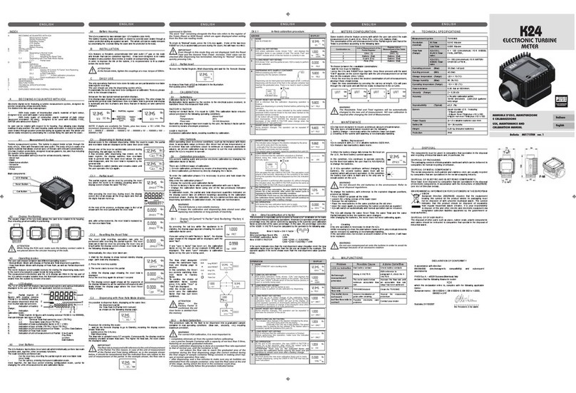
P EXPLODEDVIEWS AND OVERALLDIMENSIONS
A DECLARATION OF CONFORMITY
Theundersigned:
PIUSIS.p.AViaPacinotti 16/A z.i.Rangavino
46029Suzzara- Mantova- Italy
HEREBY STATES
underits own responsibility,that theequipment describedbelow:
Descriprion: METER
Model: K24
!"#$%&'()*+"#,'#"-"#'./'0/.'1)*+"#'23/4('/('56'7&%."'%-89":'./'7#/:);.<"%#'/-'
*%()-%;.)#",'#"-"#'./'.3"'="%#'/-'7#/:);.$/('23/4('/('.3"'56'7&%."'%-89":'./'.3"'
7#/:);.$2'$(';/(-/#*$.='4$.3'.3"'&">%&'7#/?$2$/(2'$(:$;%.":'$('.3"':$#";.$?"2','
@'6&";.#/*%>(".$;'5/*7%.$+$&$.='A$#";.$?"'BCCDEFCGE65''
H3"':/;)*"(.%.$/('$2'%.'.3"':$27/2%&'/-'.3"';/*7"."(.'%).3/#$.='-/&&/4$(>'*/.$?%.":'
#"I)"2.'%.'J$)2$'!K7KLK'/#'-/&&/4$(>'#"I)"2.'2"(.'./'.3"'"*%$&'%::#"22,':/;M.";N
7$)2$K;/*H3"'7"#2/('%).3/#$2":'./';/*7$&"'.3"'.";3($;%&'8&"'%(:':#%4')7'.3"':";&%-
#%.$/('$2'O../'P%#$($'%2'&">%&'#"7#"2"(.%.$?"K
' !)QQ%#%R'CFECFEBCFB' ' ' OttoVarini
' ' ' ' ' &">%&'#"7#"2"(.%.$?"K
B GENERAL WARNINGS
Important
precautions
Toensureoperatorsafetyand to protect thepump frompo-
tential damage,workersmust be fully acquainted with this
instruction manual beforeperforming anyoperation.
Symbolsused
in themanual
Thefollowing symbols will be usedthroughoutthe manual
to highlight safety informationand precautions of particular
importance:
ATTENTION
Thissymbolindicatessafe working practices foropera-
torsand/orpotentiallyexposedpersons.
WARNING
Thissymbolindicatesthat thereis riskof damageto the
equipmentand/orits components.
NOTE
Thissymbolindicatesuseful information.
Manualpres-
ervation
hismanualshouldbe complete andlegible throughout. It
should remainavailableto end users andspecialistinstallation
andmaintenance techniciansfor consultation atany time.
Reproduction
rights
All reproduction rights arereservedby PiusiS.p.A. The text
cannot be reprinted withoutthe written permission of Piusi
S.p.A.
THISMANUALIS THE PROPERTYOF Piusi S.p.A.
ANYREPRODUCTION, EVEN PARTIAL, ISFORBIDDEN.
C SAFETY INSTRUCTIONS
C.1 SAFETY WARNINGS
Mains- prelim-
inarychecks
before instal-
lation
ATTENTION
Youmust avoidany contactbetweenthe electrical pow-
er supplyand the uidthat needs to beFILTERED.
Maintenance
control
Before anychecksor maintenancework are carriedout, dis-
connect thepower source.
C.2 FIRST AID RULES
Contactwith
theproduct
In theevent of problems developing following EYE/SKIN
CONTACT,INHALATION or INGESTION of thetreatedproduct,
please refer to theSAFETY DATA SHEET of theuid handled.
NOTE Please refer tothe safetydata sheetfor the product
SMOKING
PROHIBITED
Whenoperating thedispensing system andin particular dur-
ing refuelling,do not smoke and donot use opename.
C.3 GENERAL SAFETY RULES
Essentialpro-
tectiveequip-
mentcharac-
teristics
Wear protective equipmentthat is:
suited to theoperationsthat need tobe performed;
resistantto cleaning products.
Personalpro-
tectiveequip-
mentthat
mustbe worn
Wear the following personal protective equipmentduring
handlingand installation:
safety shoes;
close-tting clothing;
protective gloves;
safety goggles;
Protective
equipment
instruction manual
C.4 PACKAGING
FOREWORD K24 COMES PACKED INA CARDBOARD BOXWITH A LABEL
INDICATINGTHE FOLLOWING DATA:
1 - contentsof the pack-
age
2 - weight of thecontents
3 - description of the
product
C.5
PACKAGE CONTENTS/PRE-INSPECTION
FOREWORD Toopen the packaging, usea pair of scissorsor a cutter,being careful
not todamage thedispensing systemor its components.
NOTE In theeventthat oneor more ofthe componentsde-
scribed below aremissingfrominside thepackage,
please contactPiusiinc technicalsupport.
WARNING Checkthatthe data onthe platecorrespondto the
desiredspecications. Inthe eventof anyanomaly,
contactthe supplier immediately, indicatingthe nature
of thedefects. Do notuse equipmentwhichyou suspect
might notbe safe.
D BECOMING ACQUAINTEDWITH K24
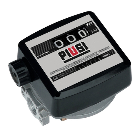
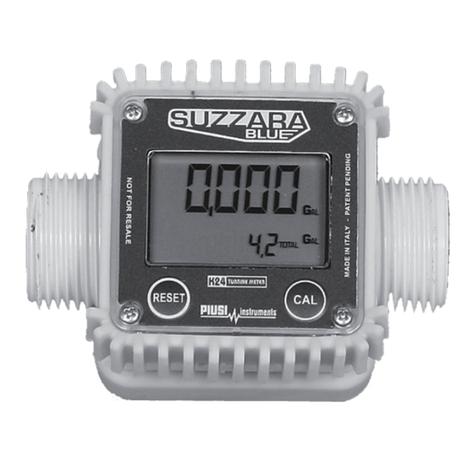
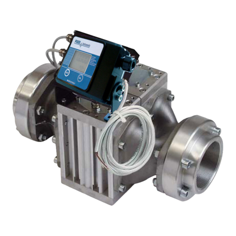
FOREWORD Electronicdigitalmeter featuring a turbinemeasurement system,de-
signed forprecisemeasuring of lowviscosity uids.
K24is availablein 2 versions:
1METER – withLCD displayand calibrationbuttons
2
PULSER – single-channel impulse, cannectable with a remote display.
Twobig groups aresuitablefor its use:
AWithbody madeof inconductive plastic materialof lightcolour,
divided into highow rateversionsand low owrate versions, with
stainlesssteel F/Fbushing
BWithbody madeof conductiveplastic material of darkcolourwith
galvanized steel bushing
owrate values Highow rate 120l/min
Lowow rate60 l/min
D.1 COMPATILE LIQUIDS
Turbine
measurement
system
Theturbine isplaced inside a hole throughthe body of k24, tted
withM-M threaded inlet andoutlet.The suppliedF-F bushingenables
several combinations of threads. K24 HAS2 RUBBERPROTECTIONS,
DESIGNEDTO ACT ASGASKETSTOO.
Theliquids compatiblewith k24 areat low viscosity, namely:
bodymade of incon-
ductiveplasticmaterial
of light colour
Water
Aus32 (D.E.F., Ad-Blue)
Milknot suitable forhuman consumption
bodymade of conduc-
tiveplastic materialof
darkcolour
Diesel fuel
Windscreen
Maincomponents:K24 Meter Main components:K24 Pulser
1 LCDdisplay 1 Plate with technicaldata
2 RESETkey 2 F-Fbushing
3 CAL key
4 F-F bushing
1
234
12
D.2 DISPLAY LCD
FOREWORD The“LCD”of theMETER featurestwo numericalregisters andvarious
indications displayed tothe user onlywhen theapplicable function
so requires.
1 Partial register (5 gureswith moving
commaFROM 0.1to 99999)indicating
the volumedispensed since the reset
button waslast pressed
6 Indication of type of total,( TOTAL /
ResetTOTAL);
2 Indication of battery charge 7 Indication of unit of measurementof
Totals: L=Litres Gal=Gallons
3 Indication of calibrationmode 8 Indication of Flow Rate mode
4 Totalsregister (6 gureswith moving
commaFROM 0.1to 999999), thatcan
indicatetwo types ofTotal:
4.1.
GeneralTotalthatcannotbe reset(TOTAL)
4.2. Resettable total (Reset TOTAL)
9 Indication of unit of measurementof
Partial: Qts=Quarts Pts=Pints
L=Litres Gal=Gallons
5 Indication of total multiplication factor
(x10 / x100)
456
9
7
1
2
3
8
D.3 DISPLAY POSITIONING (METER VERSION ONLY)
FOREWORD The squareshape of thek24 body allowsthe card tobe rotatedin its
housing, thus ensuringgreat versatilityin positioning
This allows easy display readings in any position. The card housing
is closed by a plastic cover sealed through a rubber protection act-
ing as a gasket as well. This can be easily removed unscrewing the
4 screws that x both the cover and the card (1).
ATTENTION While xingthe K24card,make surethe battery con-
tactcableis not placed above thecircularhousing of
thebulb.
D2 USERS BUTTONS
FOREWORD The METER features two buttons (RESET and CAL) which individ-
ually perform two main functions and, together, other secondary
functions
.
MAIN
FUNCTIONS
PERFORMED
- forthe RESET key, resetting thepartial register and Reset Total
- forthe CAL key, enteringinstrument calibrationmode
SECONDARY
FUNCTIONS
Used together, the two keys permit entering conguration mode
where the desired unit of measurement can be set.
LEGEND CALIBRATEMEANSPERFORMINGACTIONS ON THEMETER KEYS.
BELOW IS THELEGEND OFTHESYMBOLS USEDTODESCRIBE
THEACTIONSTO BEPERFORMED
SHORT
PRES
SURE
OF CAL
KEY
CAL
LONG
PRES
SURE
OF CAL
KEY
CALCAL
CAL
SHORT
PRES
SURE
OF
RESET
KEY
RESET
LONG
PRES
SURE
OF
RESET
KEY
RESET
RESET
RESET
E OPERATING MODES
OPERATING
MODES
Theuser can choose between two dierent operatingmodes:
Themeter featuresa non-volatile memoryfor storing the dispensing
data,even in theevent ofa completepowerbreak forlong periods.
Themeasurement electronics and the LCD display are tted in the top
part ofthe K24 which remains isolated fromthe uid-bathmeasure-
mentchamberand sealedfrom the outside by means of a cover.
1 - Normal
Mode
Normal Mode:Mode withdisplayof Partialand Total dis-
pensed quantities
2 - Flowrate
Mode
FlowRate Mode:Mode withdisplayof Flow Rate, aswell as
Partial dispensed quantity.
F INSTALLATION
FOREWORD K24 features a threaded, perpendicularinlet andoutlet (1”BSP male
and femalethat can becombinedtogether). It hasbeen designedto
be easily installed in any position:xed in-line or mobileon a dispens-
ing nozzle. In order to improvethe lifeof the turbine,it is recommend-
ed tot a strainerbeforethe meteritself
ATTENTION An F/Fcoupling, complete with itsgasket, is supplied
forinstallations on male couplings.Alwaysscrew the
sidewith gasket on K24.
It isup to the installer touse anothergasket on the
other sideof the coupling.
Thegasketused hasthe followingcharacteristics: at
sealid=24,od=35.5, thick=2 Material:NBR 70SH
Forinstallations onsystem,position K24so that the
battery housingcan be easily reached.
G DAILY USE
FOREWORD
Theonly operationsthat needto be donefor daily use are partial and/
or resettabletotalregister resetting. The user should useonly thedis-
pensingsystemof k24. Occasionally themetermay needto be con-
gured or calibrated.Todo so, pleasereferto the relevant chapters.
Beloware the twotypicalnormal operation displays. One display pageshows thepar-
tialand resettotal registers. The other shows the partialand general total. Switchover
fromresettable total to general totaldisplayis automatic and tiedto phasesand times
thatare in factory setand cannotbe changed.
NOTA 6 digits areavailable for Totals, plus two icons x 10 /
x100. Theincrement sequenceis the following:
0.0-> 99999.9-> 999999 -> 100000x 10 -> 999999x
10 ->100000x 100 ->999999 x 100
G.1 DISPENSING IN NORMAL MODE
FOREWORD
Normal mode is the standarddispensing.While thecountis made,the
partial and resettable totalare displayed at thesame time (resettotal).
WARNING Shouldone of the keys be accidentally pressed during
dispensing, this willhave no eect.
STAND BY A few seconds after dispensing hasended, onthe lowerregister,the
display switches fromresettable total to general total: theword reset
above the word total disappears, and thereset total is replacedby
the general total.
Thissituation is called standby and remainsstable until theuser
operates the k24again.
G.1.1 PARTIAL RESET (NORMAL MODE)
Thepartial register can bereset by pressing the resetkey when
the meter is in standby, meaning when the displayscreen
shows the word“TOTAL”.
Afterpressing the resetkey, during reset, thedisplayscreen
rstof all showsall the lit-updigits andthen all thedigitsthat
arenot lit up.
At theend of the process, a displaypage is rstof all shown
withthe resetpartial andthe resettotal
and,after a fewmoments, the reset total is replaced bythe
non resettableTotal.
G.1.2 RESETTING THE RESET TOTAL
The reset total resetting operation can only be performed
after resetting the partial register. The reset total can in
fact be reset by pressing the reset key at length while
the display screen shows reset total as on the following
display page:
Schematically, the stepsto be takenare:
1 Waitfor the display to shownormal standbydisplaypage
(withtotal only displayed)
2 Pressthe resetkey quickly
3 Themeter startsto resetthe partial
4 Whilethe display pageshowingthe resettotal is displayed
Press the resetkey again for at least 1 second
5 The display screenagain shows allthe segments of the
display followed byall the switched-o segmentsand
nally shows thedisplaypage wherethe resetReset
Totalis shown.
C.2 DISPENSING WITH FLOW RATE MODE DISPLAY
It is possibleto dispense uids, displaying at the same
time::
1 the dispensed partial
2 the Flow Ratein [Partial Unit/ minute]as shown onthe
following display page:
Procedure forenteringthis mode:
1 wait for the Remote Display to go toStandby, meaning
the display screen shows Total only
2 quicklypress theCAL key.
3 Start dispensing
Theow rate isupdatedevery 0.7 seconds. Consequently, the display could be relatively
unstable at lowerow rates. The higher theow rate,the morestable thedisplayed
value.
IMPORTANT Theow rateis measured withreferenceto the unitof
measurement of the Partial. Forthis reason, incase of
theunit of measurementof the Partial andTotal being
dierent, as inthe example shown below, it should be
remembered thatthe indicated owrate relatesto
theunit of measurementof the partial.In the example
shown, theow rateis expressedin Qts/min.
Theword “Gal” remaining alongsidethe owrate
refers tothe register of the Totals (Reset orNON Reset)
which areagain displayed whenexitingfromthe ow
ratereading mode.
Toreturnto “Normal”mode, pressthe CAL keyagain. Ifone of the twokeys RESETor
CAL isaccidentallypressedduring thecount,this will have noeect.
IMPORTANT
Even though in thismodethey arenot displayed,boththe
ResetTotalandthe General Total(Total) increase. Their
valuecan be checked afterdispensing hasterminated,
returningto “Normal” mode,by quickly pressingCAL.
G.2.1 PARTIAL RESET (FLOW RATE MODE)
Toreset thePartialRegister, nishdispensing andwait for
the RemoteDisplayto show a Flow Rateof 0.0 as indicated
in theillustration
thenquickly press RESET
H CALIBRATION
Whenoperating close to extremeuse or ow rate conditions (closeto minimum or
maximum acceptablevalues),an on-the-spotcalibration may be required to suit
the real conditions inwhich theK24 is required to operate.
H1 DEFINITIONS
CALIBRATION
FACTOR OR
“K FACTOR”
Multiplicationfactor applied by thesystem tothe electrical pulses
received, to transform these intomeasured uid units.
FACTORYK
FACTOR
Factory-set defaultfactor. It is equal to 1,000. Thiscalibration factor
ensures utmostprecisionin the following operating conditions:
Fluid water/ureasolutionor liquidfood products
Temperature: 20°C
Flowrate: 10- 30 ltr/min
Evenafter anychangeshave beenmade by theuser,the factoryk
factor canbe restored by means of a simple procedure.
USERK FACTOR: Customized calibrationfactor,meaningmodiedby calibration.
H2 CALIBRATION MODE
Whycalibrate? 1 Display the currently used calibration factor:
2Return to factory calibration(FactoryK Factor) after a pre-
viouscalibration by the user
3Change the calibration factorusing oneof the two previ-
ouslyindicated procedures
FOREWORD
Two procedures are available for changing the Calibration Factor:
1 In-Field Calibration,performedby meansof a dispensing
operation
2 DirectCalibration, performed by directly changingthe
calibration factor
In calibration mode, the partial and total dispensed quantities indicated on thedisplay
screen takeon dierent meanings according to thecalibration procedurephase.
In calibration mode, the K24 cannot beused for normal dispensingoperations.
In“Calibration”mode, the totalsare not increased
ATTENTION TheK24 features a non-volatile memory thatkeeps
thedata concerning calibrationand total dispensed
quantitystoredfor an indenite time,evenin the
caseof a longpower break;after changing the bat-
teries,calibration neednot be repeated.
H.2.1 DISPLAY OF CURRENT CALIBRATION FACTOR
AND RESTORING FACTORY FACTOR.
CALCAL
CAL By pressing the CAL key while the appli-
anceis in Standby, the display page ap-
pearsshowing thecurrent calibration fac-
tor used. If no calibration has ever been
performed, orthe factory setting has
been restored afterprevious calibrations,
the following display page will appear:
The word “Fact” abbreviation for“factory”
showsthat the factory calibration factor
is beingused
If,on the otherhand, calibrationshave
beenmade by theuser,the display page
willappear showingthe currently used
calibration factor ( in our example 0,998) .
Theword“user”indicatesa calibration fac-
torset by the useris beingused..
CAL
Theow chart alongside
shows the switchoverlogic
fromone display page to
another
In thiscondition, theReset
key permitsswitching
fromUser factor to Factory
factor.
Toconrmthe choiceof
calibration factor, quickly
press CAL while“User”or
“Fact”are displayed.
Afterthe restart cycle, the
K24 uses the calibration
factor thathas just been
conrmed
CAL
CALCAL
CAL
RESET
RESET
TIMEOUT
ATTENTION When the Factory Factor is conrmed, the oldUser
factor isdeletedfrom thememory
H.2.2 IN FIELD CALIBRATION
FOREWORD This procedure calls for the uid to be dispensed into a gradu-
ated sample container in real operating conditions ( ow rate,
viscosity, etc.) requiring maximum precision.
ATTENTION For correct K24 calibration,it is mostimportantto:
1Whenthe Factory Factoris conrmed, theold User factoris deleted
fromthe memory
2use a preciseSampleContainer witha capacityof not lessthan 5
litres,featuring an accurate graduated indicator.
3ensure calibration dispensing isdone at a constant ow rate equiva-
lentto that of normal use, until thecontainer is full;
4Not reducethe ow rate to reach thegraduated area of thecon-
tainer during thenal dispensingstage (the correct method during
the nal stages of sample container lling consists in making short
top-ups atnormal operation owrate) ;
5afterdispensing,wait a fewminutesto make sureany air bubbles
areeliminated from the samplecontainer; onlyread theReal value
at theend of thisstage, during which the levelin the containercould
drop.
6Carefullyfollowthe procedureindicated below.
H.2.2.1 IN-FIELD CALIBRATION PROCEDURE
ACTION DISPLAY
1NONE
Meter in Standby
2
CALCAL
CAL
LONG CALkey keying
TheMeterenterscalibration mode,shows<<CAL>>and
displaysthe calibrationfactorin use insteadof partial.The
words “Fact”and“USER”indicatewhichof the twofactors
(factory or user)is currently in use.
Important: This factor is that which theinstrumentalso usesfor
eldcalibration measurementoperations
3
RESET
RESET
RESET
LONG RESETkeykeying
TheMetershows“CAL” andthe partial at zero.The Meter is
ready toperformin-eldcalibration.
4DISPENSINGINTOSAMPLE CONTAINER
Without pressingany key,start dispensing into thesample
container
Dispensing can be interrupted and started again atwill.
Continuedispensinguntilthe levelof theuid in thesample
container hasreachedthe graduated area. Thereis no needto
reach a presetquantity.
Indicated value Realvalue
5
RESET
SHORT RESETkeykeying
TheMeteris informed thatthe calibrationdispensing
operation is nished.
Makesure dispensing is correctlynishedbeforeperforming
thisoperation. Tocalibrate the Meter, the valueindicatedby
thepartialtotaliser(example9.800)must beforcedto the
realvaluemarkedon the graduated samplecontainer.In the
bottom leftpart ofthe display an arrowappears(upwardsand
downwards),that shows the direction(increase or decrease)of
thevalue changedisplayedwhen thefollowing operations 6
or 7 areperformed.
6
RESET
SHORT RESETkeykeying
Thearrowchangesdirection.The operation canbe repeated to
alternate thedirection of the arrow.
7
CALCAL
CAL
CAL
SHORT/LONGCAL keykeying
Theindicatedvalue changesin the directionindicated by the
arrow
- oneunitfor everyshort CALkey keying
- continuallyif theCAL key is kept pressed.Thespeed increase
risesby keepingthe key pressed. Ifthe desired valueis
exceeded, repeat the operations frompoint(6).
8
RESET
RESET
RESET
LONG RESETkeykeying
TheMeteris informed that thecalibration procedure is nished.
Beforeperforming this operation, makesurethe INDICATED
value is thesame asthe REALvalue.
.
Indicated value Realvalue
TheMetercalculatesthe new USERK FACTOR ; this calculation
could requirea few seconds,dependingon the correction to
be made
ATTENTION: Ifthisoperationis performed after action (5),
withoutchangingtheindicatedvalue,the USERK FACTORwould
bethesameas theFACTORYK FACTOR,thusitis ignored.
9
NOOPERATION
Atthe end ofthe calculation, thenew USERK FACTOR is shown
fora few seconds,afterwhich therestartcycleis repeated to
nally achieve standby condition.
IMPORTANT:Fromnowon, theindicated factorwillbecome
thecalibration factor used bythe Meterandwill continue to
remain such evenaftera batterychange
10
NO OPERATION
TheMeterstoresthe new workcalibration factorand is
ready tobegin dispensing,usingthe USERK FACTOR that
hasjust beencalculated.
.
H.2.3 DIRECT MODIFICATION OF K FACTOR
If normal Meter operation shows a meanpercentage error, thiscan be corrected by ap-
plying to the currentlyused calibration factor a correction of the samepercentage. In this
case, the percentagecorrection of the USER K FACTOR must be calculated bythe opera-
torin the followingway
1"4';%&K'S%;./#''''T''''O&:'5%&'S%;./#''U ( )
FCC'@'6V
FCC
Example:
Errorpercentagefound: E% - 0.9%
CURRENT calibrationfactor: 1.000
New USER K FACTOR: 1.000* [(100 – ( - 0.9))/100] = 1.000 * [(100 + 0.9)/100] = 1.009
If theMeter indicates lessthan the real dispensed value(negative error) thenew calibra-
tionfactor mustbe higherthan theold one as shown in the example. The oppositeap-
pliesif the Meter shows morethan the real dispensed value(positive error).
ACTION DISPLAY
1
NONE
METER in Standby.
2
CALCAL
CAL
LONG CALKEY KEYING
Meter enters calibrationmode,shows “CAL” anddisplays the
calibrationfactorbeing usedinstead of the partial.The words
“Fact”and“User”indicate whichof thetwo factors (factory or
user) is currently being used.
3
RESET
RESET
RESET
LONG RESETKEYKEYING
TheMetershows“CAL” andthe zeropartialtotal.
Meter is ready toperformin-eldcalibration bydispensing–
seeprevious paragraph.
4
RESET
RESET
RESET
LONG RESETKEYKEYING
Wenow go onto Directchangeof the calibrationfactor:
theword“Direct”appears togetherwith theCurrently Used
calibrationfactor. Inthe bottom left part ofthe display, an
arrow appears(upwards or downwards)dening thedirection
(increase or decrease) ofchangeof the displayed value when
subsequent operations 5 or 6 are performed.
5
RESET
SHORT RESETKEYKEYING
Changesthe direction of thearrow.Theoperation can be
repeatedto alternate thedirection ofthe arrow.
6
CALCAL
CAL
CAL
SHORT/LONGCAL KEYKEYING
Theindicatedvalue changesin the directionindicated by the
arrow
- oneunitfor everyshort CALkey keying
- continuallyif theCAL key is kept pressed.Thespeed increase
risesby keepingthe key pressed. Ifthe desired valueis
exceeded, repeat the operations frompoint(5).
7
RESET
RESET
RESET
LONG RESETKEYKEYING
TheMeteris informed thatthe calibrationprocedure is
nished.
Beforeperforming this operation, makesurethe INDICATED
value is that required.
8
NOOPERATION
Atthe end ofthe calculation, thenew USERK FACTOR is shown
fora few seconds,afterwhich therestartcycleis repeated to
nally achieve standby condition.
IMPORTANT:Fromnowon, theindicated factorwillbecome
thecalibration factor used bythe Meterandwill continue to
remain such evenaftera batterychange
9
NOOPERATION
TheMeterstoresthe new workcalibration factorand is ready
tobegin dispensing,usingthe USERK FACTOR thathas just
beenchanged.
I METER CONFIGURATION
TheMETER feature a menu withwhich theuser can select themain measurement unit,
Quarts(Qts),Pints (Pts), Litres (Lit), Gallons (Gal);
The combination of the unit of measurement of the Partial register and that of the
Totals is predened according to the following table:
Combinationno. Unitof Measurement
Partial Register Unitof Measurement
Totals Register
1 Litres (L) Litres (L)
2 Gallons (Gal) Gallons (Gal)
3 Quarts(Qts) Gallons (Gal)
4 Pints (Pts) Gallons (Gal)
Tochoosebetween the4 available combinations:
1Wait forthe METER togo to Standby
2
CAL
RESET
+
Thenpressthe CALand RESETkeys together. Keep these pressed
until theword“UNIT”appears on the screen together withthe unitof
measurementset at thattime(in thisexampleLitres/ Litres)
3 Everyshort press of theRESET key, the variouscombina-
tionsof the units of measurementsare scrolled as shown
below:
Gal
Qts
Pts
Gal
RESET
RESET
RESET
4
CALCAL
CAL By pressing the CALkey at length, thenew settings will
be stored, the METER willpass through thestart cycleand
willthen be ready to dispensein the setunits.
ATTENTION The Reset Total and Total registers will be auto-
matically changed to the new unit of measure-
ment.
NO newcalibration is required afterchanging the
Unitof Measurement.
L MAINTENANCE
BATTERY
REPLACEMENT
Use 2x1.5V alkalinebatteries sizeAAA
WARNING K24shouldbe installed in a position allowingthe
batteriesto be replaced without removing it from
thesystem.
K24 features two low-battery alarm levels:
1When the battery charge falls below the rst level on the LCD,
the xed battery symbol appears. In this condition, K24 con-
tinues to operate correctly, but the xed icon warns the user
that it is ADVISABLE to change the batteries.
2If K24 operation continues without changing the batteries,
the second battery alarm level will be reached which will
prevent operation. In this condition the battery icon starts to
ash and is the only one to remain visible on the LCD.
o change the
batteries, with
reference to the
exploded diagram
positions, proceed
as follows
1 Press RESET to update all the totals
2 Loosen the 4 xing screws of the lower cover
3 Remove the old batteries
4 Place the new batteries in the same position as the
old ones
5 close the cover again, by positioning the rubber pro-
tection as a gasket
6 K24 will switch on automatically and normal opera-
tion can be resumed
The K24 will display the same Reset Total, the same Total and the same Partial indi-
cated before the batteries were changed.
After changing the batteries, the meter does not need calibrating again.
CLEANING Only one operation is necessary to clean the k24.
After removing k24 from the plant where it was built
in, any residual elements can be removed by washing
or mechanically-handling.
If this operation does not restore a smooth rotation of
the turbine, it will have to be replaced.
ATTENTION Do notdiscardthe oldbatteries in the environment.
Refer tolocal disposalregulations.
Do not use compressed air onto the turbine in
order to avoid its damage because of an exces-
sive rotation
K24Front face replacement
1Carefullyremove thescrewsfrom thecornersof the
front panel, and thencarefully liftthe frontcoverup
awayfromthe main bodyof the meter.
2Carefullyremove thescrewsfrom thecornersof the
front panel, and thencarefully liftthe frontcoverup
awayfromthe main bodyof the meter.
3
Whenthenew panelis tted make sure thepower
adapter is tted correctlywith thelocation pin in the
correctway
4Carefullyretthe display panelbackonto the main
bodymakingsure thewire is tucked into thecorner
andreplacethe screws
M MALFUNCTIONS
Problem Possible cause Remedial Action
LCD: no indication Bad battery contact Check batterycontacts
Notenough measure-
mentprecision
Wrong K FACTOR Withreferenceto paragraph H,
checkthe K FACTOR
Themeter worksbelow
minimum acceptable ow rate.
Increasethe ow rateuntil an
acceptable owrate rangehas
beenachieved
Reduced or zeroow
rate TURBINEblocked Clean the TURBINE
Themeter doesnot
count, butthe ow
rateis correct
Incorrect installation of
gears after cleaning
Repeat the reassembly pro-
cedure
Possible electronic card
problems Contact your dealer
ELECTRONIC TURBINE
METER - PULSER
N DISPOSAL
Foreword If thesystem needs tobe disposed, the parts which makeit up
mustbe delivered to companiesthat specialize in the recycling
and disposal of industrial waste and, in particular:
Disposing of pack-
ingmaterials
Thepackagingconsistsof biodegradable cardboard which canbe
delivered to companies fornormal recycling of cellulose.
Metal PartsDis-
posal
Metalparts, whetherpaint-nished or in stainless steel, can be
consigned to scrap metal collectors.
Disposal of electric
andelectronic
components
These mustbe disposed of by companies that specialize in the
disposal of electroniccomponents, in accordance withthe indica-
tionsof directive2002/96/CE (see text ofdirective below).
Informa-
tionregard-
ingthe en-
vironment
forclients
residing
within theEuro-
peanUnion
EuropeanDirective 2002/96/EC requiresthat allequipment
marked withthis symbol on the product and/or packagingnot
be disposed of together with non-dierentiated urbanwaste.
Thesymbol indicates thatthis product must not bedisposedof
together with normal household waste. It isthe responsibilityof
the owner todisposeof these productsas well asother electric or
electronic equipment by means of thespecicrefuse collection
structures indicated by thegovernment orthe local governing
authorities.
Miscellaneous
partsdisposal
Othercomponents, such aspipes, rubber gaskets, plastic parts
and wires, must bedisposedof by companiesspecialisingin the
disposal of industrial waste.
P EXPLODED VIEWS AND OVERALL DIMENSIONS
/VISTE ESPLOSE ED INGOMBRI
