Piusi K40 User manual

Bulletin M0164B ENES_00
Use and maintenance
EN
Uso y mantenimiento
ES
K40
MECHANICAL
METER

M0164B
2 /16
Use and maintenance
Bulletin M0164B
ENGLISH
1 GENERAL WARNINGS 3
2 FIRST AID RULES 3
3 GENERAL SAFETY RULES 4
4 GENERAL INFORMATIONS 4
5 INSTALLATION 4
6 USE 5
7 MAINTENANCE 5
8 DISASSEMBLY AND REASSEMBLY 5
9 TECHNICAL DATA 6
10 PROBLEMS, CAUSES AND SOLUTIONS 6
11 DISPOSAL 7
12 EXPLODED DIAGRAM 14
13 OVERALL DIMENSION 15
TABLE OF CONTENTS

3/124
3 /16
This manual is the property of PIUSI S.p.A. Any reproduction, even partial, is forbidden.
EN
(translated from italian) K40 MECHANICAL METER
1 GENERAL WARNINGS
Important
precautions To ensure operator safety and to protect the pump from potential damage,
workers must be fully acquainted with this instruction manual before per-
forming any operation.
Symbols used
in the manual The following symbols will be used throughout the manual to highlight safety
information and precautions of particular importance:
ATTENTION
This symbol indicates safe working practices for operators and/or poten-
tially exposed persons.
WARNING
This symbol indicates that there is risk of damage to the equipment and/or
its components.
NOTE
This symbol indicates useful information.
Manual preser-
vation This manual should be complete and legible throughout. It should remain
available to end users and specialist installation and maintenance techni-
cians for consultation at any time.
Reproduction
rights All reproduction rights are reserved by Piusi S.p.A.
The text cannot be reprinted without the written permission of Piusi S.p.A.
© Piusi S.p.A.
THIS MANUAL IS THE PROPERTY OF Piusi S.p.A.
ANY REPRODUCTION, EVEN PARTIAL, IS FORBIDDEN.
This manual belongs to Piusi S.p.A., which is the sole proprietor of all rights
indicated by applicable laws, including, by way of example, laws on copy-
rights. All the rights deriving from such laws are reserved to Piusi S.p.A.: the
reproduction, including partial, of this manual, its publication, change, tran-
scription and notification to the public, transmission, including using remote
communication media, placing at disposal of the public, distri¬bution, market-
ing in any form, translation and/or processing, loan and any other activity
reserved by the law to Piusi S.p.A..
2 FIRST AID RULES
Contact with
the product In the event of problems developing following EYE/SKIN CONTACT, INHA-
LATION or INGESTION of the treated product, please refer to the SAFETY
DATA SHEET of the fluid handled.
Electrocution disconnect the unit from the mains, or use a dry insulator as protection while
moving the electrocuted person far from any conductor. Do not touch the
electrocuted person with bare hands until he/she is far from any conductor.
Ask qualified and trained people for help immediately
NOTE Please refer to the safety data sheet for the product
SMOKING
PROHIBITED When operating the dispensing system and in particular during refuelling, do
not smoke and do not use open flame.

M0164B
4 /16
Use and maintenance
3 GENERAL SAFETY RULES
Essential
protective
equipment
characteristics
Wear protective equipment that is:
suited to the operations that need to be performed;
resistant to cleaning products.
Personal
protective
equipment that
must be work
safety shoes;
close-fitting clothing;
protective gloves;
safety goggles;
Other
equipment instruction manual
Protective
gloves Prolonged contact with the treated product may cause skin irritation; always
wear protective gloves during dispensing.
4 GENERAL INFORMATIONS
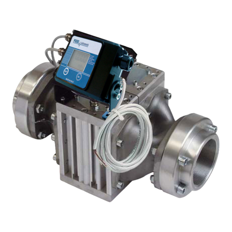
The K40 mechanical flow meter with oval gears has been designed to allow accurate measurement of
oil or other liquids that are compatible with the component materials. The oval gears of the measuring
chamber (see diagram) are moved by the fluid, and they activate the gear train housed in the lid of the
flow meter body, which transmits the motion to the counter.
The counter is fitted with a total indicator, which cannot be reset, in litres or quarter gallons and with
a partial indicator which can be reset using the button provided.
ATTENTION To ensure correct and safe use of the flow meter, it is necessary to read
and comply with the instructions and warnings contained in the present
manual.
Incorrect installation or use of the flow meter could cause danger for
people and things.
5 INSTALLATION
The K40 flow meter can be installed in any position, with flexible and rigid piping as well as directly
on pumps and tanks.
The flow meter has one preset flow direction.
If solid particles get into the measuring chamber, they could prevent the correct operation of the oval
gears.
Therefore, make provision to filter the fluid by installing a filter before the flow meter (recommended
filter: 400 ŋ).

5/124
5 /16
This manual is the property of PIUSI S.p.A. Any reproduction, even partial, is forbidden.
EN
(translated from italian) K40 MECHANICAL METER
6 USE
Once installed, the K40 flow meter is ready for use. Press the RESET button until the partial indicator
returns to zero.
The total indicator cannot be reset in any way. Make sure that, during use, the operating pressure does
not exceed the valued indicated in the “Technical Data” section.
7 MAINTENANCE
If installed and used correctly, the K40 flow meter does not require any ordinary maintenance work.
Inadequate filtration on the line before the flow meter could cause the measuring chamber to wear
out or become clogged, which may consequently affect the accuracy of the flow meter. Should this
problem arise (see “Problems, Causes and Solution” section), disassemble the measuring chamber as
shown in the “Disassembly/Reassembly” section.
ATTENTION Before disassembling, make sure that all the liquid has been removed
from the flow meter and the pipes connected to it.
To carry out the required cleaning, use a soft brush or a small tool (a screwdriver for example), taking
care not to damage the measuring chamber during cleaning.
Carefully inspect the flow meter and replace any damaged parts using only original spare parts, as
shown in the “Spare Parts Exploded Diagram”.
8 DISASSEMBLY AND REASSEMBLY
The K40 flow meter can be easily disassembled into its main components, without having to separate
the body from the piping.
MEASURING CHAMBER
To access the measuring chamber:
ARemove the rubber protection
BUnscrew the 6 screws located under the flow meter body
CRemove the lid
DRemove the gasket and the oval disk
ERemove the gears
To reassemble the parts, carry out the above-mentioned steps in reverse order, taking particular to:
-Install the gasket seals correctly after having checked and lubricated them;
-Tighten the screws correctly;
-Ensure that, if you hold the flow meter with the inlet facing down, the outlet gear is on the right-
hand side;
-Check that the oval gears are turning correctly;
-Check that the gears on the lid correspond with the that in the chamber outlet.

M0164B
6 /16
Use and maintenance
9 TECHNICAL DATA
DATA REFERENCE VALUE
Mechanism Oval Gears
Flow Rate Range 1 – 30 lit/min.
0,26 – 7,9 gal/min.
Operating Pressure Max 70 bar
Bursting Pressure Min 210 bar
Storage Temperature Range -20 - +80 °C
Storage Humidity Max 85% RH
Operating Temperature Range -10 - +60 °C
Pressure loss with
SAE 10W40 oil at 20°C
(15 l/min) (bar) 0.7
Accuracy +/- 1%
Repetitivity Typical +/- 0.2%
Partial Indicator 3 + 1 digits
Total Indicator 6 digits
Resolution (of the indication) 0.1 litres - 0.1 quarts
Connections Inlet/Outlet ½” BSP - ½” NPT
Weight 0,78 Kg
Packaging Dimensions 160x130x115 mm
Versions - Indication in litres with GAS threaded inlet and outlet
- Indication in gallons with NPT threaded inlet and outlet
10 PROBLEMS, CAUSES AND SOLUTIONS
PROBLEM POSSIBLE CAUSE CORRECTIVE ACTION
Unsatisfactory
accuracy Measuring chamber is dirty or clogged Clean the measuring chamber following
the instructions shown in the “disassem-
bly and reassembly” section
Presence of air in the liquid Identify and eliminate leaks in the suc-
tion lines
Low flow rate Measuring chamber is dirty or clogged Clean the measuring chamber following
the instructions shown in the “disassem-
bly and reassembly” section
Filter is clogged or dirty Clean the filter

7/124
7 /16
This manual is the property of PIUSI S.p.A. Any reproduction, even partial, is forbidden.
EN
(translated from italian) K40 MECHANICAL METER
11 DISPOSAL
Foreword If the system needs to be disposed, the parts which make it up must be delivered to
companies that specialize in the recycling and disposal of industrial waste and, in
particular:
Disposing of
packing
materials
The packaging consists of biodegradable cardboard which can be delivered to com-
panies for normal recycling of cellulose.
Metal Parts
Disposal Metal parts, whether paint-finished or in stainless steel, can be consigned to scrap
metal collectors.
Disposal of
electric and
electronic
components
These must be disposed of by companies that specialize in the disposal of electronic
components, in accordance with the indications of directive 2012/19/UE (see text of
directive below).
Information
regarding the
environment
for clients
residing within
the European
Union
European Directive 2012/19/UE requires that all equipment marked with this symbol
on the product and/or packaging not be disposed of together with non-differentiated
urban waste. The symbol indicates that this product must not be disposed of together
with normal household waste. It is the responsibility of the owner to dispose of these
products as well as other electric or electronic equipment by means of the specific
refuse collection structures indicated by the government or the local governing au-
thorities.
Disposing of RAEE equipment as household wastes is strictly forbidden. Such wastes
must be disposed of separately.
Any hazardous substances in the electrical and electronic appliances and/or the mis-
use of such appliances can have potentially serious consequences for the environ-
ment and human health.
In case of the unlawful disposal of said wastes, fines will be applicable as defined by
the laws in force.
Miscellaneous
parts disposal Other components, such as pipes, rubber gaskets, plastic parts and wires, must be
disposed of by companies specialising in the disposal of industrial waste.

M0164b
14 /16
Uso y mantenimiento
12 VISTAS EXPLODIDAS • EXPLODED DIAGRAM
Some components may vary in shape and color or not be present. Always follow codes and quantity shown in list. ○fixed components □variable components - - - only reference
K40 MECHANICAL METER LR_C00041 JULY 2019
1
2
3
5
6
7

15/124
15 /16
El presente manual es propiedad de PIUSI S.p.A. Queda prohibida toda reproducción, ya sea total o parcial.
ES
(Traducido del italiano) K40 MECHANICAL METER
13 MEDIDAS DE OCUPACIÓN • OVERALL DIMENSION
43 49.6
92.6
100
18.5
O1/2" BSP
112

EN. This document has been drawn upwith the greatest aention to precision and accuracy of all data herein contained. Nevertheless, PIUSI
S.p.A. denies liability for any possible mistake or omission.
ES. El presente documento ha sido redactado prestando la máxima atención a la precisión de los datos en él contenidos.
PIUSI S.p.A. no se hace responsable de posibles errores y omisiones.
© PIUSI S.p.A.
Bulletin M0164b ENES_00 06.2020
Table of contents
Other Piusi Measuring Instrument manuals

Piusi
Piusi K33 Atex User manual

Piusi
Piusi K24 Use and care manual

Piusi
Piusi K500 User manual

Piusi
Piusi K24 User manual

Piusi
Piusi K24 Use and care manual

Piusi
Piusi MK325 Service manual

Piusi
Piusi K24 User manual

Piusi
Piusi DELPHIN PRO X User manual

Piusi
Piusi K33 Atex User manual

Piusi
Piusi K900 Instruction manual
Popular Measuring Instrument manuals by other brands

janitza
janitza UMG 604 Installation and putting into service

horiba
horiba LAQUA 200 Series quick guide

PCB Piezotronics
PCB Piezotronics IMI SENSORS 621B51 Installation and operating manual

Delta Electronics
Delta Electronics Temperature Measurement Module DVP04PT-H2 instruction sheet

Busch-Jaeger
Busch-Jaeger 1091 U operating instructions

Klein Tools
Klein Tools CL150 instruction manual