PMK FireFly SMA Input User manual

Instruction Manual
FireFly®
High Voltage Optically-Isolated Probe
with Universal BNC Interface
>1.5 GHz, >180dB CMRR
Preliminary
DE | EN

FireFly®Instruction Manual
2
Copyright © 2023 PMK - All rights reserved.
Manufacturer
PMK Mess- und Kommunikationstechnik GmbH
Königsteiner Str. 98
65812 Bad Soden, Germany
Tel: +49 (0) 6196 999 5000
Internet: www.pmk.de
E-Mail: sales@pmk.de
Warranty
PMK warrants this product for normal use and operation within specifications for a period of one year
from date of shipment and will repair or replace any defective product which was not damaged by
negligence, misuse, improper installation, accident or unauthorized repair or modification by the buyer.
This warranty is applicable only to defects due to material or workmanship. PMK disclaim any other
implied warranties of merchantability or fitness for a particular purpose. PMK will not be liable for any
indirect, special, incidental, or consequential damages (including damages for loss of profits, loss of
business, loss of use or data, interruption of business and the like), even if PMK has been advised of
the possibility of such damages arising from any defect or error in this manual or product.

FireFly®Instruction Manual
3
Table of Contents
Manufacturer........................................................................................................................................................ 2
Warranty............................................................................................................................................................... 2
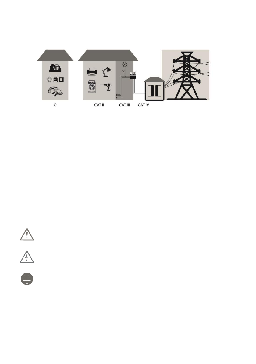
Compliance Information....................................................................................................................................... 4
IEC Pollution Degrees............................................................................................................................................ 5
IEC Safety Symbols................................................................................................................................................ 5
Safety and Handling Information.......................................................................................................................... 6
Safety and Handling Information (Continued)...................................................................................................... 7
Lithium-Ion 18650 Battery Charging and Storage Information........................................................................ 7
Clearance Requirements ................................................................................................................................. 8
About FireFly®....................................................................................................................................................... 9
Factory Calibration ............................................................................................................................................... 9
Specifications...................................................................................................................................................... 10
Electrical Specifications1................................................................................................................................ 10
Electrical Specifications (Continued) ............................................................................................................ 11
Environmental Specifications ........................................................................................................................ 12
Physical Specifications................................................................................................................................... 12
Dimensions.................................................................................................................................................... 12
Typical Common Mode Rejection Ratio (CMRR) ........................................................................................... 13
Typical Maximum Differential Input Voltage (CW)........................................................................................ 13
Typical Frequency Response ......................................................................................................................... 14
Typical Differential Input Impedance ............................................................................................................ 14
User Interface..................................................................................................................................................... 15
Interface Box Controls & Indicators............................................................................................................... 15
Probe Status Indicator................................................................................................................................... 15
Probe Head Battery Level Indicators ............................................................................................................. 15
Probe Head Power ON/OFF Button............................................................................................................... 16
Auto-Zero Button .......................................................................................................................................... 16
Remote Interface................................................................................................................................................ 16
Getting Started ................................................................................................................................................... 16
Cable Selection.............................................................................................................................................. 17
Connection to the Test Points (Circuit-Under-Test)....................................................................................... 17
Making the Measurement............................................................................................................................. 17
Scope of Delivery ................................................................................................................................................ 18
Ordering Information.......................................................................................................................................... 19

FireFly®Instruction Manual
4
Compliance Information
The FireFly®probing system complies with the following relevant union harmonization legislation, safety
and environmental standards. Only professionals and qualified personnel should use this product.
Serious injury or death may occur as result of incorrect usage of this product.
Probe
IEC/EN 61010-1:2010 - Safety Requirements for Electrical Equipment for Measurement, Control
and Laboratory Use, Part 1: General Requirements
IEC/EN 60825–1 - Safety of Laser Products Part 1: Equipment Classification and Requirements
-Edition 3 (2014)
US 21CFR Part 1010 - Performance Standards for Electronic Products: General
US 21CFR Part 1040 - Performance Standards for Light- Emitting Products
Laser Certification: Class 1 Laser Product
This product complies with 21 CFR 1040.10 and 1040.11 except for deviations pursuant to Laser
Notice No. 50, dated June 24, 2007.
CAUTION. Use of controls or adjustments for performance of procedures other than those
specified herein may result in hazardous exposure.
Battery
EU model: CE conform. More information follow soon.
US model: UL conform. More information follow soon.
Asian model: PSE conform. More information follow soon.

FireFly®Instruction Manual
5
IEC Pollution Degrees
Definitions and Examples:
Overview of measurement categories according to IEC 61010-01
O = No Measurement Category (Other circuits that are not directly connected to mains)
Pollution Degree 1
No POLLUTION or only dry, non conductive POLLUTION. NOTE: The
POLLUTION has no influence.
Pollution Degree 2
Only- non conductive POLLUTION. Occasionally, however, a temporary
conductivity caused by condensation must be accepted.
Pollution Degree 3
Conductive POLLUTION occurs or dry, non-conductive POLLUTION
occurs which becomes conductive due to condensation which is to be
expected.
IEC Safety Symbols
The following symbols may appear on the product or in this instruction manual:
Caution, risk of danger. Refer to manual.
Caution, risk of electric shock.
Earth (ground) TERMINAL.

FireFly®Instruction Manual
6
Safety and Handling Information
The probe head, tip cables and accessories are NOT for hand-held use. The overall safety of any
measurement setup incorporating this probe is the responsibility of the user.
The probe head is optically-isolated, galvanically isolated, from the measuring
system and earth ground.
To avoid personal injury and to prevent fire or damage to this product or products
connected to it, review and comply with the following safety precautions. Be aware that if
you use this probe assemblyin a manner not specified the protection this product provides
may be impaired. Only qualified personnel should use this probe assembly.
Beware of High Voltages.
Observe probe and probe accessory ratings. Do not apply any electrical potential to the
probe input which exceeds the maximum ratings of the probe head, tip cables or the
accessories con¬nected to it. In a combination, the lower rating / measurement category
applies to both the probe and accessories connected to it. Make sure to comply with the
voltage versus frequency derating curve.
Do not connect the probe head/tip cable to an energized circuit to avoid the risk of shock.
Always de-energize the circuit-under-test before installing or removing the probe head or
tip cable from the circuit-under-test. The plastic case of the probe head and insulating
sleeve on the tip cable do not supply adequate isolation
Keep away from hazardous live circuits.
Avoid open circuitry. Do not touch connections or components when power is present.
Maintain safe clearance from the Probe Head and Tip Cable while connected to the
energized circuit
Avoid unnecessary stress.
The small electrical components of the probe are sensitive to shock and impact. Avoid
anyunnecessary stress to the probe like throwing, falling and strong vibrations.
The FireFly®fiber cable between the probe head and the interface box contains multiple
optical fibers. Avoid tight radius bends, crushing, crimping, twisting, or otherwise stressing
of the fiber cable. Do not crush, crimp, twist, pull, jerk or sharply bend the fiber-optic cable.
Avoid making loops in the fiber-optic cable smaller than 12.7cm (5in).
Avoid over-bending the Probe Head's Tip Cables; do not exceed the minimum bend radius
of 5cm (2in).
Keep products clean and dry.
Remove all connections of the probe before cleaning. Keep the fiber cable clean and free
from contaminants in order to maintain the 60kV common mode voltage rating.
Inspect the fiber cable for dirt, contaminants or damage before each use and clean using
a dry, lint-free cloth. If dirt remains, use a soft cloth or swab dampened with a 75%
isopropyl alcohol solution and rinse with deionized water. A swab is useful for cleaning
narrow spaces, use only enough solution to dampen the swab or cloth. Do not use
abrasive compounds on any part of the probe.
Do not use chemical cleaning agents; they may damage the probe. Avoid using chemicals
that contain benzine, benzene, toluene, xylene, acetone, or similar solvents.
Continues on next page.

FireFly®Instruction Manual
7
Safety and Handling Information (Continued)
Do not operate with suspected failures.
Refer to qualified service personnel.
Do not operate in wet or damp conditions.
Condensation may occur if a unit is moved from a cold to a warm environment.
Do not operate the product in an explosive atmosphere.
Connect and disconnect properly.
The circuit-under-test MUST BE DE-ENERGIZED (TURNED OFF) when handling,
connecting & disconnecting the Probe Head, Tip Cables or Accessories to the circuit.
Use ONLY non-conductive probe head & tip holders.
Use only PMK recommended 18650 batteries in the probe head.
Avoid applying an input signal without batteries in the probe head.
Use only the originally provided carry case to store or transport the probe not in use.
If the probe is no longer being used, and before the probe is placed back into the probe
case, remove the battery from the probe head for storage.
Lithium-Ion 18650 Battery Charging and Storage Information
For optimal charging, the ambient temperature during charging should be 24±2.5°C. Batteries should
be stored in a dry, room temperature space. Avoid any situations that might subject the batteries to
either extreme cold or heat. Between the range of -20°C to +50°C (-4°F to +122°F) is sufficient but the
most optimal storage temperature is somewhere around 77°F or 25°C.
Before handling the probe head to change the battery, make sure the circuit under test
has been de-energized or has been disconnected from the circuit-under-test.
Use ONLY the PMK recommended 18650 batteries, in the probe head. If using a battery with a built in
USB charge port, connect the appropriate USB cable and connect to a USB port on the oscilloscope,
wall wart or PC. Use only the PMK recommended charger.
Charging times will vary based on the battery and the charger used.
Observe batterysafety: The FireFly®probe head is powered bya user-replaceable 18650
rechargeable Lithium-Ion battery.
To avoid personal injury or property damage due to electrical burst, smoke, fire or explosions,
please operate the probe within the specified operating conditions.
Do not drop the probe or subject it to strong impacts.
Do not use the probe if it has been damaged in any way.

FireFly®Instruction Manual
8
Clearance Requirements
The probing system can be used for very high common mode voltages. Observe all pre-cautions and
information from the manual when using this product. See also Specifications and Derating curves in
this manual.
Maintain at least 1m (40in) safe clearance of the probe head, tip cable and tip cable
accessories in all directions when connected to an energized circuit.
RF burn hazard zone around the probe head and tip cable
Maximum Safe Handling Limits
Common Mode Voltage (Probe Head to Earth Ground)
1 6,00E+04 4,24E+04 4,24E+04
1,00E+01 6,00E+04 4,24E+04 4,24E+04
1,00E+02 6,00E+04 4,24E+04 4,24E+04
1,00E+03 6,00E+04 4,24E+04 4,24E+04
1,00E+04 6,00E+04 4,24E+04 4,24E+04
1,00E+05 6,00E+04 4,24E+04 4,24E+04
8,00E+05 6,00E+04 4,24E+04 4,24E+04
1,00E+06 6,00E+04 4,24E+04 4,24E+04
2,00E+06 6,00E+04 4,24E+04 3,00E+04
3,40E+06 6,00E+04 4,24E+04 2,00E+04
5,00E+06 6,00E+04 4,24E+04 1,30E+04
6,50E+06 6,00E+04 4,24E+04 1,00E+04
1,20E+07 6,00E+04 4,24E+04 5,60E+03
2,00E+07 6,00E+04 4,24E+04 3,50E+03
1,00E+08 6,00E+04 4,24E+04 7,00E+02
1,00E+09 6,00E+04 4,24E+04 1,00E+02
1,50E+09 6,00E+04 4,24E+04 2,50E+01
2,00E+09 6,00E+04 4,24E+04 1,00E+01
0
10
20
30
40
50
60
70
110 100 1000 10000 100000 1000000 10000000 100000000 1E+09
Common Mode Voltage [kV]
Frequency [Hz] - Continuous Wave
Common Mode Voltage [VPEAK]
Common Mode Voltage [VRMS]
RF Burn Area
1m (40in)
Away from
Probe Head
1 10 100 1k 10k 100k 1M 10M 100M 1G

FireFly®Instruction Manual
9
About FireFly®
The FireFly®high voltage opticallyisolated probe offers industry leading performance that combines the
ability to accurately resolve high bandwidth, small differential signals in the presence of large common
mode voltages with its ultra-high common mode rejection performance across its entire bandwidth. With
> 1.5GHz bandwidth, wide differential input range, unmatched CMRR up to > 180dB (1 billion to 1
rejection), and a 60kV common mode, FireFly®is the ideal measurement solution for both GaN and SiC
device characterization and system level design development.
PMK‘s optically isolated interface and unique compact angled probe head design are the key attributes
that set FireFly®apart from the other solutions in the market, providing very stable and accurate
measurements over a wide temperature range and easy access to the measurement points in tight
spaces.
The compact angled probe head design allows for shorter tip cables to be used, resulting in higher
signal fidelity measurements and reduced stresses placed on the measurement test point. FireFly®‘s
wide selection of probe tip connections and accessories offer reliable, hands-free, high-fidelity
connectivity to the measurement points. Using industry standard MMCX and square pins connections
allow FireFly®to easily interface to test boards that have already been design with these test points.
The FireFly®probe head is powered by an easy to change, rechargeable, industry standard 18650
battery that provides continuous operation for up to 30h at room temperature. FireFly®has a universal
BNC output connector and is compatible with any oscilloscope with a 50Ω input impedance or 1MΩ
input impedance and a 50Ω feed-through termination, allowing FireFly®to be used on any oscilloscope
in the lab. For accurate deskew, each probe‘s unique propagation delay is measured and added to each
probe label.
FireFly®can be controlled from the controls located on the interface box or via remote control. The „PMK
Probe Control“ software provides the ability for the user to control the probe remotely via a computer,
and provides the user with a graphical user interface. The software is free of charge, and included with
PMK’s 2ch and 4ch power supplies PS-02 and PS-03, which are required to power the probe. The PS-
02 and PS-03 power supplies all have a USB interface and are available with optional LAN interface.
The new AP-01, 1 channel battery pack power supply, provides > 8h of portable and isolated operation
which allows the user the flexibility of where the probe can be used. The AP-01 supplies power only to
the probe with no software remote control.
Factory Calibration
Annual re-calibration is recommended. ISO17025 calibration upon delivery or as re-calibration will be
possible on request.

FireFly®Instruction Manual
10
Specifications
The probe head and tip cables are not for handheld use. Observe adequate spacing between probe
head components and earth ground. The probe can beused without probe tip. Warm up time 20minutes.
Read the safety instructions beforefirst use. This product is not rated for CAT II, III orIV. Do not exceed
the specifications.
Electrical Specifications1
The final specification table is coming soon.
FireFly®
Bandwidth
(-3dB)
Rise time
(10% - 90%)
Input
Attenuation
Input Impedance 2
SMA Input
> 1.5 GHz
<300 ps -
preliminary
1X
200 kΩ || 5.1 pF
FF-MMCX-1V
> 1.5 GHz
<300 ps -
preliminary
1X
50 Ω 3
FF-MMCX-10V
> 1.3 GHz
<300 ps -
preliminary
10X
2 MΩ || 3.4 pF
FF-MMCX-25V
> 1.3 GHz
<300 ps -
preliminary
25X
TBD
FF-MMCX-50V
> 1.3 GHz
<300 ps -
preliminary
50X
10 MΩ || 2 pF
See next page for more Electrical Specifications.
This product comes with 1 year warranty. Specifications that are not marked with (*) as guaranteed are
typical.
Notes:
¹ Determined when using a PS-02 power supply at +23°C ambient temperature.
2For input voltage and input impedance derating graphs, see below.
3Terminated, 50 Ω transmission line.
4as defined in IEC 61010-1. Rated for indoor, dry location use only.
5Galvanically isolated FireFly®probe head through fiber optic connection.
6CMRR performance is >180dB below 500kHz. See CMRR graph.
Maximum Rated Input Voltages 4
Common Mode
Voltage 5
(Maximum Voltage
to Earth)
± 60 kV (DC + Peak AC)
No Measurement
Category
Linear Input Voltage Range
(DC + Peak AC) 2
Maximum Non-Destruct Differential
Input Voltage
(DC + Peak AC) 2
SMA Input
± 1 V
5 V (preliminary)
FF-MMCX-1V
± 1 V
5 V (preliminary)
FF-MMCX-10V
±10 V
50 V (preliminary)
FF-MMCX-25V
± 25 V
TBD
FF-MMCX-50V
± 50 V
100 V (preliminary)
Pollution Degree
2

FireFly®Instruction Manual
11
Electrical Specifications (Continued)
Common Mode
Rejection Ratio
DC
1 MHz
100 MHz
200 MHz
500 MHz
1 GHz
SMA Input
> 180 dB
173 dB
105 dB
95 dB
90 dB
80 dB
FF-MMCX-1V
> 180 dB
TBD
TBD
TBD
TBD
TBD
FF-MMCX-10V
> 180 dB
TBD
TBD
TBD
TBD
TBD
FF-MMCX-25V
> 180 dB
TBD
TBD
TBD
TBD
TBD
FF-MMCX-50V
> 180 dB
TBD
TBD
TBD
TBD
TBD
DC Gain Accuracy
< 2 % ± DC Offset voltage - preliminary
Noise (input referred)
SMA Input (1X): < 1.9 mV rms - preliminary
With tip cable: (SMA Input noise) · (Tip cable input attenuation) 7
scales proportionally to tip attenuation
DC Offset Voltage
(input referred)
SMA Input (1X): < 2 mV (After Auto-Zero) –preliminary
With tip cable: (SMA Input offset voltage) · (Tip cable input attenuation) 8
scales proportionally to tip attenuation
Propagation Delay
2 m fiber cable: 15 ns
The probe specific value is measured and printed on interface box label,
tip cable approx. 500 ps
Battery Life
> 30 h @ 22 ⁰C – 25 °C, > 20 h @ 0 ⁰C, >4 h @ 50 ⁰C
Dependent on probe head operating temperature
(Continuous Operation)
Output Termination
& Coupling
50 Ω DC
Battery Type
Protected 18650 Li-Ion, Rechargeable, 3.7V Certified
Laser Certification
Laser Class 1
IEC/EN 60825-1:2014, US 21CFR Part 1010, US 21CFR Part 1040
Notes:
7Example: 10x tip FF-MMCX-10V noise = 10x SMA input noise.
8Example: 10x tip FF-MMCX-10V offset = 10x SMA input offset.

FireFly®Instruction Manual
12
Environmental Specifications
Parameter
Specification
Temperature
Range
Operating
Probe Head &
Interface Box
0 ⁰C to +50 ⁰C
Tip Cables &
Adapters
-40 ⁰C to +85 ⁰C
Non-Operating
Probe Head &
Interface Box
-20 ⁰C to +71 ⁰C
Tip Cables &
Adapters
-40 ⁰C to +85 ⁰C
Maximum Relative
Humidity
Operating
Probe Head &
Interface Box
5 % to 85 % RH (relative
humidity) at up to +40 °C, 5 % to
45 % RH above +40 °C up to
+50 °C, non-condensing
Non-Operating
Tip Cables &
Adapters
5% to 85% RH (relative
humidity) at up to +85 °C, non-
condensing
Probe Head &
Interface Box
5 % to 85 % RH (relative
humidity) at up to +40° C, 5 % to
45 % RH above +40° C up to
+71° C, non-condensing
Maximum Altitude
Operating
3000 m (9843 ft)
Non-Operating
15000 m (49213 ft)
Physical Specifications
Parameter
Specification
Weight
Probe
325 g
Tip Cable
11 g
Length
Tip Cable
9.5 cm (3.74")
Fiber Cable
2 m (6.56 ft)
Connectors
Probe
Input: SMA (Female) –Probe Head
Output: BNC (Male) - Interface Box
Dimensions
The dimensions shown are in mm. Drawings from the probe tips are coming soon.

FireFly®Instruction Manual
13
Typical Common Mode Rejection Ratio (CMRR)
FireFly®Typical CMRR Performance
# Channel 1
# Trace 1
Frequency
Preliminary PT1 - Probe Head SMA Input
10X Tip 50X Tip
11,60E+02
9,00E+03 1,60E+02
1,01E+06 1,56E+02
3,01E+06 1,52E+02
1,00E+07 1,41E+02
3,52E+07 1,20E+02
7,02E+07 1,10E+02
1,00E+08 1,04E+02
1,50E+08 1,00E+02
2,01E+08 9,40E+01
3,01E+08 8,90E+01
6,05E+08 9,00E+01
8,00E+08 8,00E+01
9,05E+08 7,40E+01
1,00E+09 8,00E+01
1,50E+09 6,00E+01
1,99E+09 5,00E+01
0
20
40
60
80
100
120
140
160
180
110 100 1000 10000 100000 1000000 10000000 100000000 1E+09 1E+10
CMRR [dB]
Frequency [Hz]
Preliminary PT1 - Probe Head SMA Input
10 100 1k 10k 100k 1M 10M 100M 1G
Typical Maximum Differential Input Voltage (CW)
Note that the maximum input voltage rating of the probe decreases as the frequency of the
applied signal increases.
The maximum input voltage derating is coming soon.

FireFly®Instruction Manual
14
Typical Frequency Response
The typical frequency response is coming soon.
Typical Differential Input Impedance
Note that the maximum input voltage rating of the probe decreases as the frequency of the
applied signal increases.
Typical Differential Input Impedance FireFly®Series

FireFly®Instruction Manual
15
User Interface
Interface Box Controls & Indicators
Probe Status Indicator
Indicator
Status
Action/Information
Green
(Solid)
READY
Probe Head
Power ON
Successful powered up and probe head is on and warmed
up. Ready for measurements.
Green
(Blinking)
Auto-Zero In
Process
Auto-Zero is in process - Very fast. Probe head not ready.
De-energized circuit unter test required.
Red
(Solid)
Probe Head
Power OFF
Caution - Probe Head is powered OFF and not able to
pass a signal. Probe head not ready. Do not energize your
circuit under test.
Yellow
(Solid)
Probe Head
Warm Up
Probe head has successfully powered up and warming up
Probe head not ready. Do not energize your circuit under
test.
Blue
(Solid)
Power Up
Powering up and running self-checks. Probe head not
ready. Do not energize your circuit under test.
Red
(Blinking)
Error
Condition
An error condition has occurred - Power cycle the probe &
check probe head battery. Probe head not ready. Do not
energize your circuit under test.
Probe Head Battery Level Indicators
Indicator
Status
Action/Information
Green
(Solid)
Normal Operation
1 - 4 Green LEDs
Ready for measurements. Four (4) Solid
Green LEDs indicates the battery is full and
One (1) Solid Green LED indicates the
battery will soon need to be replaced.
Bottom Green
(Blinking)
Low Battery
Battery replacement recommended.
Bottom Orange
(Blinking)
Low Battery
(Critical Warning)
Warning - Battery needs to be changed.
Bottom Red
(Blinking)
Empty or NO Battery
Installed
Action required: Probe Head is NO longer in
operation and passing a signal
- De-energize your circuit
- Check and replace battery
Probe Status Indicator
Auto-Zero Button
Probe Head Battery Level Indicators
Bottom Battery Level Indicator
Probe Head Power ON/OFF Button

FireFly®Instruction Manual
16
Probe Head Power ON/OFF Button
Turn the probe head ON before use and power OFF after use to conserve the battery. The Interface
Box will power up even if the probe head is in the Probe Head OFF mode. See Probe Status Indicator
Information.
When the Probe Head is in the OFF mode, the probe will not pass a signal.
Auto-Zero Button
Press the Auto-Zero Button on the probe interface box to remove any DC offset errors (drift) in the
probe's output. See Probe Status Indicator overview for more information.
Make sure the circuit-under-test is de-energized. No signal must be applied to probe tip.
Remote Interface
The "PMK Probe Control“ software, available free of charge, provides the ability for the user to control
the probe remotely via a computer, and provides the user with a graphical user interface.
Download: www.pmk.de/probecontrol
In order to achieve the highest CMRR and minimum CM loading, keep the probe head away from
surrounding metal or earth ground.
Getting Started
Refer to this FireFly®Instruction Manual for complete operating information and specifications before
first use. The latest Instruction Manual can be downloaded at www.pmk.de/FireFly
1) Connect the FireFly®Interface Box to the BNC input of the oscilloscope or other measurement
system with either an internal or external 50Ω input termination. If using a tip cable, attach the tip
cable to the probe head SMA connector by turning it clockwise until fully tightened, so the tip cable
is secure and not loosen up when in use. Set the propagation delay on the oscilloscope to the
measured propagation value printed on the FireFly®Interface Box's label and add the tip
cable/accessory delay if one is used. Set the oscilloscope’s attenuation scale factor to the tip
cable's attenuation.
2) Connect the PMK Power Supply, model 2ch PS2, 4ch PS3 or battery pack AP-01, to the power
connector on the FireFly®Interface Box using a PMK Probe Connection Cable. Turn on the Power
Supply. The Interface Box Probe Status Indicator turns red and the Probe Head Battery Level
Indicators will light to indicate the probe head’s battery level.
Before handling the probe head, tip cable or tip cable accessories, make sure the
circuit-under-test is either de-energized or not connected to the probe.
3) If a battery change is required, open the probe head’s battery compartment by unscrewing the
battery cap counter-clockwise. Insert or replace the existing battery with a fully charged 18650
rechargeable battery, in order to achieve the longest probe head operating time. Followthe polarity
markings on the compartment. Make sure that the positive end of the battery goes in first and the
negative end of the battery is facing out, towards the battery cap. Close the probe head’s battery
compartment by screwing the battery cap back onto the probe head in the clockwise direction and
tighten.
4) Press the Probe Head Power ON/OFF Button to turn on the probe head. Wait for the Probe Status

FireFly®Instruction Manual
17
Indicator on the interface box to turn green, which means the probe is now ready to make a
measurement.
5) If a probe holder is being used, use non-conducting probe holders only and connect the probe head
to the probe holder by aligning the attachment interface and then rotating it 90° to securely lock the
probe head and holder together.
6) Attach the probe tip cable or accessory input connector to the circuit-under-test.
7) Press the Auto-Zero button onthe interface boxto remove any DC offset errors (drift)in the probe's
output.
8) Ready to use: Apply power to the circuit-under-test to begin making the measurements.
Cable Selection
Each tip cable has a set of labels on them that specify the linear input voltage range as well as the
attenuation factor to correctly setup the scale factor on the oscilloscope to display the correct signal
amplitudes. When selecting a tip cable for the measurement being made, consider the following criteria:
1) Maximum DC + AC peak voltage at the test point to be measured
2) Minimum differential loading (input resistance and capacitance) that test circuit can tolerate
3) Minimum needed sensitivity for the measurement (minimum V/div setting)
Connection to the Test Points (Circuit-Under-Test)
To achieve the best performance from the FireFly®probe, use an MMCX connector as close to the test
point as possible. The MMCX connectors provide a compact footprint and solid metal body that provide
the best signal fidelity of the signal being measured as well as shielding down as close as possible to
the test point. This connection also provides a stable and repeatable measurement.
To achieve the best electrical performance, especially the CMRR performance and EMI susceptibility,
place the probe tip adapter/accessories as close as possible to the circuit board.
To minimize the effects of common mode capacitive loading of the probe head/tip cable and maximum
CMR, consider the following items:
Whenever possible, connect the coaxial (common) shield of the tip cable to the test point that has
the least dynamic signal, with respect to earth ground, relative to the tip cable signal (center) test
point in the circuit-under-test.
The coaxial (common) shield of the tip cable and tip cable adapters should always be connected
to the lowest impedance point (usually a circuit common or power supply rail) in the circuit-under-
test (relative to the tip cable/center conductor) to obtain the most accurate waveform.
Increasing the physical distance between the probe head/tip cable and any conductive surface
will reduce the parasitic capacitance.
Making the Measurement
To achieve the best CMRR performance, make sure to tighten the tip cable to probe SMA connection.
Avoid fiber movement when making a precise measurement.

FireFly®Instruction Manual
18
Scope of Delivery
Not all required items are included in the scope of delivery of the base probe FireFly®FF-1500. See
Ordering Information to configure your individual probing solution and select a required PMK power
supply. The following accessories are included in the scope of delivery.
2x 18650 Rechargeable Lithium Ion Batteries
USB Wall Charger + USB Cable (for Battery Charging)
Interface Box Probe Connection Cable (0.5m), 890-520-900
Probe Head Holder 2-Footer (Bi-Pod), FF-2FOOTER
Set marker bands (4x4 Colors)
Instruction Manual
Read me First Flyer
The accessories for this probe series have been safety tested.
Do not use any other accessories, batteries or power supplies than what is recommended.

FireFly®Instruction Manual
19
Ordering Information
Step 1: Select Base Probe
FF-1500
FireFly®optical isolated probe, 1.5GHz, >180dB, 2m fiber cable (2 batteries &
2footer included, required power supply to be ordered separately)
Step 2: Select Probe Tip Cables
The probe tip cables are interchangeable without requiring any tools. The probe head SMA input range
is ±1V with no attenuation.
FF-MMCX-1V
FireFly®probe tip cable, MMCX, ±1V, >1.5GHz, 1x attenuation,
50Ω terminated for shunt measurements
FF-MMCX-10V
FireFly®probe tip cable, MMCX, ±10V, >1.3GHz, 10x attenuation
FF-MMCX-25V
FireFly®probe tip cable, MMCX, ±25V, >1.3GHz, 25x attenuation
FF-MMCX-50V
FireFly®probe tip cable, MMCX, ±50V, >1.3GHz, 50x attenuation
Step 3: Select Connectivity Accessories
Observe the frequency derating of each accessory. Observe maximum input voltage of the probe’s
input. Do not use any other accessories.
FF-SQ-MMCX5
5x MMCX to 2x 0.025'' (0.635mm) socket , -40°C to +125°C
FF-HTSPAD-MMCX3
3x MMCX solder-in cable adapter HT, 50Ω RF micro coax
to flex solder-in pad, -40°C to +155°C
FF-HTS-MMCX2
2x MMCX solder-in cable adapter HT, MMCX socket with
50Ω RF micro coax cable and open end, -40°C to +155°C
FF-UFL-MMCX2
2x MMCX cable adapter, MMCX socket with 50Ω RF micro
coax cable to UF.L plug, -40°C to +125°C
FF-2XR-MMCX
MMCX to 2x XR Mini-Hook
972416100 2-pole test clip SMD for use with FF-SQ-MMCX5
P25-2 Pico Hook™ red for use with FF-SQ-MMCX5
P25-0 Pico Hook™ black for use with FF-SQ-MMCX5
D010031 50Ω BNC feed-through for 1MΩ input oscilloscopes

FireFly®Instruction Manual
20
Step 4: Select Positioning System
FF-2FOOTER
Probe holder 2 Footer (Bipod), included in probe’s scope of delivery
FF-3DPOS200
3D positioner with steel base, 200 mm span width and FireFly®probe
holder, max 10kV
Step 5: Select Power Supply
The power supply pin assignment is different from other power supplies. Use only original PMK power
supplies with PMK probes.
889-09V-PS2
PS-02 (2 channels, with USB interface for remote control)
889-09V-PS2-L
PS-02-L (2 channels, with LAN and USB interface for remote control)
889-09V-PS3
PS-03 (4 channels, with USB interface for remote control)
889-09V-PS3-L
PS-03-L (4 channels, with LAN and USB interface for remote control)
889-09V-AP01
AP-01 (battery pack, 1 channel, no remote control)
890-520-900
Power supply cable (0,5 m), included in probe’s scope of delivery
890-520-915
Power supply cable (1,5 m)
Step 6: Select Accredited Calibration
KAL-DAKKS-FF
ISO 17025 (re-)calibration
Step 7: Select Additional Accessories
D010031
50Ω BNC feedthrough for use with 1MΩ oscilloscope inputs, 0.5W
Coming Soon / In Development
TBD
Probe tip cable, ±250V, 250x attenuation
Probe tip cable, ±500V, 500x attenuation
Probe tip cable, ±1000V, 1000x attenuation
Probe tip cable, ±2500V, 2500x attenuation
New connectivity solutions
Power-Over-Fiber adapter
This manual suits for next models
4
Table of contents
Other PMK Test Equipment manuals
Popular Test Equipment manuals by other brands

Klein Tools
Klein Tools ET200 instruction manual

Klein Tools
Klein Tools CL440 instruction manual

Kusam-meco
Kusam-meco KM 2803IN Operation manual

Associated Research
Associated Research Hypot II 4500D Operation and service manual

Parker Research Corp
Parker Research Corp B100 operating instructions

Murphy
Murphy PowerView PV-101 manual