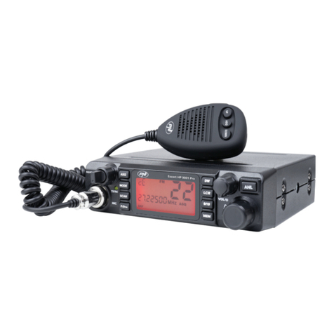
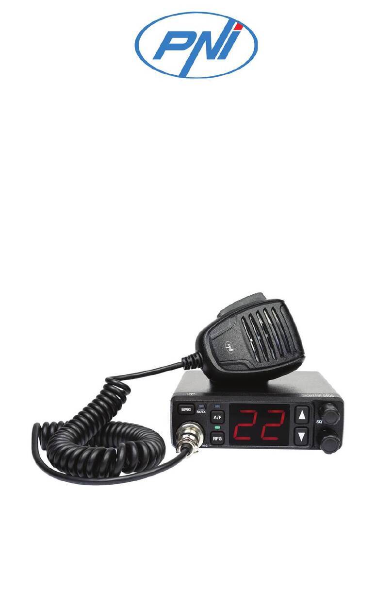
PNI Escort HP 8000L User manual

Manual de utilizare
Statie radio CB
PNI Escort HP 8000L

2
Inainte sa conectati sau sa utilizati acest produs, va rugam sa cititi cu atentie aceste
instructiuni de utilizare si pastrati acest manual pentru o utilizare ulterioara.
CUPRINS
1. CARACTERISTICI PRINCIPALE.................................................................................................................................3
2. SPECIFICATII TEHNICE...............................................................................................................................................3
3. DESCRIERE PRODUS.....................................................................................................................................................4
4. INSTALARE......................................................................................................................................................................5
5. SCHIMBARE NORMA ....................................................................................................................................................7
6. SFATURI UTILE...............................................................................................................................................................7
7. FRECVENTELE SI PUTERILE LEGALE IN EUROPA SUNT:................................................................................8
ATENTIE:
PENTRU A PREVENI RISCUL DE INCENDIU NU UTILIZATI DECAT O SURSA
DE ALIMENTARE CORESPUNZATOARE.
NU EXISTA COMPONENTE CARE POT FI REPARATE DE UTILIZATOR.
PENTRU REPARATII ADRESATI-VA UNUI SERVICE AUTORIZAT.

3
1. Caracteristici principale
•40 de canale FM/AM
•Comutator selectare mod FM/AM (AM functioneaza doar prin schimbarea normei)
•Comutator selectare canal de urgenta 9/19
•Butoane selectare canal UP/DOWN
•LED-uri indicatoare nivel semnal
•Indicator numar canal din 2 cifre
•Potentiometru volum si pornire/oprire statie
•Indicatoare LED pentru RX/TX/ASQ
•Microfon cu butoane de selectare canal (sus/jos) si activare ASQ
•Mufa microfon cu 6 pini pe panoul frontal
•Mufa pentru difuzor extern
•Squelch manual si squelch automat ajustabil
2. Specificatii tehnice
Canale
40 AM/FM
Banda de frecventa
26.965 – 27.405 MHz
Control frecventa
P.L.L.
Temperatura de functionare
-10° - +55°C
Alimentare
13.8Vdc ±15%
Dimensiuni / greutate
115 x 36x 152mm / 0.8 kg
Receptor
Frecventa intermediara
1° 10.7 MHz / 2° 450 KHz
Sensibilitate
-120dBm / 12dB SINAD (FM)
-107dBm / 12dB SINAD (AM)
Iesire audio
@10% THD 2.5W la 8 ohm
Distorsiune audio
<8% at 1 KHz
Rejectie imagine
65 dB
Canal adiacent
85 dB
Consum curent
200 mA in stand-by
Emitator
Putere maxima RF
4W FM la 13.8Vdc
Modulatie
85% la 90% (AM)
3KHz ±0.2 KHz (FM)
Impredanta antena
50 Ohm
Consum curent
2 A

4
3. Descriere produs
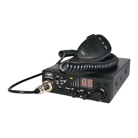
1. Conector 6 pini pentru microfon
2. Buton crestere numar canal
3. Buton scadere numar canal
4. Potentiometru ajustare squelch – squelch-ul face statia mai silentioasa prin
eliminarea zgomotelor de pe fundal. Rotiti potentiometrul in sensul acelor de
ceasornic pentru a reduce zgomotele, sau in sensul invers acelor de ceasornic daca
doriti sa auziti si cele mai slabe semnale
5. Potentiometru ASQ – pentru a creste nivelul de ASQ rotiti potentiometrul in sensul
acelor de ceasornic, in acest caz se reduce zgomotul de fundal, dar si nivelul
semnalului receptionat. RECOMANDARE: porniti statia cu ASQ rotit la stanga.
6. Potentiometru pornire/oprire statie si ajustare volum – rotiti in sensul acelor de
ceasornic pentru a porni statia si a mari volumul. Daca nu se receptioneaza nici un
semnal va sugeram sa ajustati squelch-ul (prin rotirea potentiometrului SQ in sens
invers acelor de ceasornic) si apoi volumul la un nivel confortabil. Cand este
pornita din potentiometrul de volum, statia va memora ultimul canal utilizat.
7. Buton selectare mod AM/FM. (În AM functioneaza doar prin schimbarea normei).
8. Comutator selectare canal de urgenta 19,mod normal de functionare CH, sau
blocare taste. In modul CH se pot selecta toate celelalte canale 1~40. In
Romania canalul utilizat este 22.
9. LED indicator TX/ASQ. In timpul emisiei LED-ul va fi rosu, iar cand functia ASQ
este activata LED-ul va fi verde.
10.Indicator nivel semnal – indicator cu 4 bare pentru a monitoriza puterea semnalelor
receptionate/emise
11.Ecran LED – afiseaza numarul canalului

5
12.Conector antena
13.Cablu de alimentare 13.8VDC
14.Mufa pentru difuzor extern
15.Buton PTT – apasati pentru a emite
16.Buton marire numar canal
17.Buton activare/dezactivare functie ASQ
18.Buton micsorare numar canal
19.Mufa 6 pini pentru conectarea microfonului
in statie
4. Instalare
Inainte de a instala unitatea centrala in masina, verificati si alegeti cea mai
convenabila pozitie, pentru a avea acces usor la statie si pentru a o putea folosi fara a va
deranja de la condus. Utilizati suportul si accesoriile din pachet pentru a instala statia.
Suruburile suportului trebuie stranse bine pentru a evita vibratia statiei in timpul mersului.
Suportul de montaj poate fi pozitionat deasupra sau sub statie, iar aceasta poate fi
inclinata in functie de modul de instalare (sub bord sau sub tavanul cabinei de camion).
ATENTIE: Asigurati-va ca tensiunea la care alimentati statia este cea indicata de
fabricant.

6
Instalarea unitatii centrale: inainte de a alimenta statia, asigurati-va ca butonul de
pornire este maxim la stanga. Cablul de alimentare al statiei include o siguranta de
protectie pe firul rosu. Conectati cablul de alimentare al statiei la sistemul electric al
autovehiculului cu atentie sporita la polaritate, chiar daca statia are protectia la inversarea
de polaritate. Conectati firul rosu la borna pozitiva (+) si firul negru la borna negativa (-)
a sistemului electric a autovehiculului. Verificati corectitudinea conexiunilor efectuate,
pentru a preveni deconectarea acestora sau un eventual scurtcircuit.
ATENTIE: In cazul arderii sigurantei nu o inlocuiti cu una de valoare mai mare. Cea din
fabrica are 2A.
Instalarea antenei: pentru utilizarea statiei aveti nevoie de o antena specifica ce
functioneaza in frecventa 27.225MHz. Instalarea antenei trebuie efectuata de un tehnician
specializat. Pozitionati antena corespunzator pe autovehicul. Inainte de a conecta antena
la statie este necesara verificarea antenei cu un aparat specializat, altfel se poate defecta
circuitul de emisie al statiei. De obicei antena trebuie pozitionata pe partea cea mai inalta
a autovehiculului, fara a fi obstructionata de obstacole si cat mai departe de orice sursa
electrica sau zgomot electromagnetic. Cablul coaxial al antenei nu trebuie sa fie intrerupt
sau presat. Conectati mufa din capatul cablului coaxial al antenei la mufa de antena din
spatele statiei.
Verificarea functionarii statiei: odata instalata statia si alimentata de la sistemul
electric al autovehiculului, procedati in felul urmator pentru a verifica functionarea
acesteia:
•Verificati daca alimentarea este conectata corect
•Verificati conexiunea antenei la statie
•Conectati microfonul la mufa de pe panoul frontal al statiei
•Porniti statia prin rotirea potentiometrului de volum in sensul acelor de
ceasornic si ajustati volumul la nivelul dorit
•Selectati canalul dorit prin intermediul tastelor UP/DOWN de pe panoul
frontal al statiei sau de pe microfon; in Romania se utilizeaza canalul 22
•Actionati butonul SQ in zona limita in care dispare zgomotul de fundal.
Daca modul ASQ este activat (de pe microfon) butonul SQ nu mai
functioneaza
•Apasati butonul PTT de pe microfon pentru a emite, si eliberati-l pentru a
receptiona

7
•Verificati nivelul semnalului receptionat prin intermediul barelor de semnal
de pe panoul frontal al statiei
•Porniti functia ASQ de pe microfon si reglati nivelul acestuia din butonul
ASQ de pe panoul frontal al statiei
5. Schimbare norma
Pentru a schimba norma in care utilizati statia radio CB procedati in felul umator:
•Apasati simultan butoanele Down si PTT de pe microfon si apoi porniti
statia
•Utilizati tastele up si down de pe statie pentru a selecta norma dorita
•Opriti si reporniti statia
Pentru a verifica norma curenta utilizati aceeasi procedura.
Norme disponibile: CE > -9 > -A > -b > -C > -d>-E > -F > -p > -n
•CE:26.965 - 27.405 MHz doar FM
•9: 26.965 - 26.955 80 canale AM FM (Germania)
•A: 25.615 - 26.055MHz
•b: 26.065 - 26.505MHz
•C: 26.515 - 26.955MHz
•d: 26.965 - 27.405MHz
•E: 27.415 - 27.855MHz
•F: 27.865 - 28.305MHz
•p: 26.960 - 27.400MHz
•n: 26.330 - 26.770MHz AM FM
In Romania recomandam utilizarea normei CE.
6. Sfaturi utile
•Nu inversati polaritatea de alimentare a statiei
•Nu inlocuiti siguranta arsa cu una de valoare mai mare; Cea din fabrica are
2A.
•Nu emiteti fara antena sau cu o antena defecta sau necalibrata, pentru a evita
arderea finalului de emisie
•Reglati SQ si ASQ la limita disparitiei zgomotului de fundal. Prin rotirea
butonul SQ in sensul acelor de ceasornic prea mult, nu veti receptiona decat
semnalele puternice (cele emise din apropiere)

8
7. Frecventele si puterile legale in Europa
Italia 40CH AM/FM 4 watt
Italia 34CH AM/FM 4 watt
Germania 80 CH FM 4watt/ 12 CH AM 1watt
Germania 40 CH FM 4watt/ 12 CH AM 1watt
Europa 40 CH FM 4 watt/ 40 CH AM 1watt
Romania CE 40 CH FM 4watt
Spania 40 CH AM/FM 4watt
Franta 40 CH FM 4watt/ 40 CH AM 1watt
Anglia 40 CH FM 4watt frecvente engleze + EC 40 CH FM 4 watt frecvente CEPT
ATENŢIE! Acest produs este destinat sa fie utilizat in Romania si functioneaza pe
norma CE Europa 40 CH FM 4 watt. Pentru a functiona in AM va trebui sa schimbati
norma din CE in d.
ATENŢIE! In Romania este permis doar 1 watt pentru modulatie AM!
Specificatiile se pot modifica fara preaviz!

37
USER MANUAL
CB RADIO
PNI Escort HP 8000L

2
Before connecting and using this product, please read carrefully these instruction
manual and keep it for later use.
CONTENTS
1. Main Features.............................................................................................................3
2. Technical specifications..............................................................................................3
3. Product description.....................................................................................................4
4. Installation...................................................................................................................5
5. Standard change..........................................................................................................7
6. Usefull tips..................................................................................................................7
7. Legal frequencies and transmiting powers in Europe:...............................................8
ATENTION:
TO PREVENT FIRE HAZZARDS USE PROPER POWER SOURCE.
THERE ARE NO COMPONENTS THAT CAN BE REPAIRED BY THE USER.
FOR REPAIRS PLEASE REFER TO A N AUTHORIZED SERVICE.

2
1. Main Features
•40 AM/FM channels
•Mode AM/FM switch
•9/19 emergency channel selector
•UP/DOWN buttons for channel selection
•Signal LED indicators
•2 digit channel indicator
•Volume knob with power ON/OFF control
•TX/RX /ASQ LED indicator
•Microphone with Up /Down and ASQ buttons
•Front microphone plug
•Jack for external speaker
•Manual and automatic squelch
2. Technical specifications
Channels
40 AM/FM
Frequency range
26.965 – 27.405 MHz
Frequency control
P.L.L.
Operating temperature
-10° - +55°C
DC input voltage
13.8Vdc ±15%
Size / Weight
115 x 36 x 152 mm / 0.8 kg
Receiver
IF
1° 10.7 MHz / 2° 450 KHz
Sensitivity
-120dBm / 12dB SINAD (FM)
-107dBm / 12dB SINAD (AM)
Audio output
@10% THD 2.5W la 8 ohm
Audio distortion
<8% at 1 KHz
Image rejection
65 dB
Adjacent channel
85 dB
Current drain
200 mA in stand-by
Transmitter
Maximum RF power
4W FM la 13.8Vdc
Modulation
85% la 90% (AM)
3KHz ±0.2 KHz (FM)
ANT impedance
50 Ohm
Current drain
2 A

2
3. Product description
1. MICROPHONE connector : Connect the supplied electric condenser microphone
to this connector, and then lock it via the ring nut.
2. UP KEY : Press this key and channel NO. runs up.
3. DOWN KEY : Press this key channel NO. runs down.
4. SQ knob : The SQUELCH control allows to silent the receiver by cutting the
background noise. Turn the SQUELCH knob anticlockwise until the background noise
is cut. Rotate the SQUELCH knob clockwise (SQUELCH ON) to listen to the weakest
signals.
5. ASQ knob : to increase the ASQ level rotate the knob clockwise, in this case the
backround noise is reduced but also the received signal. Reccomanded: turn on the
radio CB with the ASQ knob on the left.
6. OFF/VOL : This knob controls the radio ON and OFF as well as adjusts the volume.
If no signals are being received on the operating channel, it is suggested to turn on
the SQUELCH and adjust the volume tothe desired level while listening tothe
background noise. When it is turned on by operating the Volume knob,the radio will
remember the channel, frequency, AM or FM used last time.
7. AM/FM mode selector: This switch allows selecting the modulation mode AM/ FM.
8. Emergency channel/function mode selector/key lock:with this button you can
select the emergency channel 19, the normal CH funtioning mode or lock the front
panel keys. In CH mode you can select the channel you want to use. In Romania
they use channel 22.
9. TX/ASQ LED : The indicator is bicolour light as red and green colour. When
TX is red colour, when ASQ on is green light.
10.RX Signal Meter: 4-bar RX signal Meter to monitor the strength of the received
signals.
11. DISPLAY: The digital LED display shows the channel.

2
12.Antenna connector
13. 13.8 VDC power cord
14. EXT (External Speaker) Jack
15. PTT (Push-to-talk) key: Push the button to talk then release to receiving mode.
16. UP key 0f the microphone: This switch
allows increasing a channel number.
17. ASQ: Press this button, TX and ASQ
on the LED would be green light, shows
ASQ turn on.
18. DN key of the microphone: This switch
allows decreasing a channel number.
19. MICROPHONE plug: 6-pole
microphone plug with locking ring nut, to be
connected to socket (1) located on the front
side of the radio.
4. Installation
Before installing the main unit in the vehicle, please check and select the most
convenient position, in order that the radio will be easy to reach and comfortable to
operate without disturbing or interfering driving. Use the supplied bracket and hardware
to install the radio. The bracket screws must be well tightened to avoid looseness as the

2
vehicle vibrates. The car mounting bracket can be installed over or below the radio and
the radio may be inclined as desired according to the specific type of installation (under
dashboard or track cabin roof installation).
Installation of the main unit
Before connecting the radio to the vehicle electric system, please make sure the
radio is powered off with the OFF/VOL (6) knob completely turned anticlockwise at
OFF position. The DC power cable of the radio includes a fuse holder with fuse located
on the red positive (+) wire. Please connect the DC power cable to the vehicle electric
system with special attention to correct polarity, even if the radio is protected against
polarity inversion. Connect the red wire to the positive (+) pole and the black wire to
the negative (-) pole of the vehicle electric system. Please make sure that the wires and
terminals are firmly connected, to prevent cables from disconnecting or causing short
circuits.
Installation of the antenna
A specific mobile antenna adjusted for 27 MHz frequency range must be used. The
antenna installation must be done by a qualified technician or service centre. Please
install the antenna carefully on the vehicle with proper connection to ground. Before
connecting the antenna to the radio, it is necessary to check the correct operation of the
antenna with low standing wave ratio (S.W.R.) via adequate instruments. If not, the
transmitter circuit of the radio could be damaged. The antenna usually must be installed
on the highest part of the vehicle, free from obstacles and as far away as possible from
any source of electric or electromagnetic noise. The RF antenna coaxial cable must not
be damaged or pressed on its way between antenna and the radio. The correct operation
of the antenna and the low standing wave ratio (S.W.R.) must be checked periodically.
Connect the RF antenna coaxial cable to the antenna connector (15), located on the rear
side of the radio.
Checking operation of the radio
Once radio has been connected to the vehicle electric system and to the antenna, the
correct operation of the system should be checked. Please proceed as following:
1) Check that the power cable is correctly connected.
2) Check that the RF antenna coaxial cable is properly connected.
3) Connect the microphone to the connector (1) that is on the front side of the radio.
4) Rotate the SQUELCH (4) knob anticlockwise.
5) Turn radio on by the OFF/VOL (6) knob and adjust volume to the desired level.
6) Select the desired channel with the up/down key on the front side of the radio.
7) Rotate the SQUELCH (4) knob clockwise to cut the background noise.
8) Press the PTT key to transmit and release it to receive.

2
9) Check the level of the received and transmitted signals on the 4 bar RX signal Meter
and TX LED. The transceiver will work correctly.
5. Standard change
To change the working standard of the radio follow the next instructions:
•Simultanious press DOWN and PTT buttons on the microphone then turn
on the radio
•Use up and down buttons on the front panel of the radio to select the
desired standard
•Turn the radio off and on again
To check the current standard use the same procedure.
Available standards: CE > -9 > -A > -b > -C > -d > -E > -F > -p > -n
•CE: 26.965 - 27.405 MHz FM only
•9: 26.965 - 26.955 80 channels AM FM (Germany)
•A: 25.615 - 26.055 MHz
•b:26.065 - 26.505 MHz
•C: 26.515 - 26.955 MHz
•d:26.965 - 27.405 MHz
•E: 27.415 - 27.855 MHz
•F: 27.865 - 28.305 MHz
•p:26.960 - 27.400 MHz
•n:26.330 - 26.770 MHz AM FM
6. Usefull tips
•Do not invert power polarity
•Do not replace the fuse with a bigger one. The default is 2A.
•Do not transmit without an antenna connected, you risc damaging the
device.
•Set the SQ and ASQ at the limit of the background noise.

2
7. Legal frequencies and transmiting powers in Europe
Italy 40CH AM/FM 4 watt
Italy 34CH AM/FM 4 watt
Germany 80 CH FM 4watt/ 12 CH AM 1watt
Germany 40 CH FM 4watt/ 12 CH AM 1watt
Europe 40 CH FM 4 watt/ 40 CHAM 1watt
Romania CEPT 40 CH FM 4watt
Spain 40 CH AM/FM 4watt
France 40 CH FM 4watt/ 40 CH AM 1watt
GB 40 CH FM 4watt english frequencies + EC 40 CH FM 4 watt CEPT
frequencies
Specifications subject to change without notice!

ръководство за употреба
CB радио
PNI Escort HP 8000L

2
Преди да свързвате или използвате този продукт, моля, прочетете внимателно тези инструкции и
запази това ръководство за бъдеща употреба.
Не са открити части, които могат да бъдат поправени от потребителя.
Попитайте за ремонт воторизиран сервиз.
ВНИМАНИЕ:
за Да се предотврати рискът от възникване на пожар, използвайте само
източник на енергия съответно.
CЪДЪРЖАНИЕ
1. ОСНОВНИ ХАРАКТЕРИСТИКИ
.............................................................................................................................3
2. ТЕХНИЧЕСКИ ХАРАКТЕРИСТИКИ
......................................................................................................................3
3. ОПИСАНИЕ НА ПРОДУКТА
.....................................................................................................................................4
4. МОНТАЖ
..........................................................................................................................................................................5
5. Полезна информация
......................................................................................................................................7

3
Характеристики:
•
40 канала FM/AM
•
Избор на режим на превключване FM / AM (AM работи само чрез промяна на нормата)
•
Авариен канал превключвател 9/19
•
Бутони за избор на канал нагоре / надолу
• LED индикатори сигнализиращи ниво
•Индикатор 2-цифрен номер на канала
•потенциометър обем истарт / стоп станция
•зелена крушка (LED) индикатор за ASQ
•Бутони за избор на канал за микрофон (нагоре / надолу) иактивиране на ASQ
• 6-пинов жакза микрофон на предния панел
•крик за външен високоговорител
• CЪДЪРЖАНИЕ шумоподтискане
•Регулируемо автоматично шумоподтискане
•Антена Connector
2. технически специализации
Kанали 40 AM/FM
Честотна лента 26.965 – 27.405 MHz
Kонтрол чест P.L.L.
Работна температура -10° - +55°C
Xранене 13.8Vdc ±15%
Pазмери 115 x 36 x 152 m
m
Tегло 0.8 kg
Приемник
Междинно чест 1° 10.7 MHz / 2° 450 KHz
Чувствителност -120dBm / 12
d
B SINAD (FM)
-107dBm / 12dB SINAD (AM)
Продукция звуков @10% THD 2.5W la 8 ohm
Изопачаване звуков <8% at 1 KHz
Отхвърляне изображение 65 dB
Съседен канал 85 dB
Консумация на енергия 200
m
Ainstan
d
-
b
y

Пред
а
Макс
и
Моду
л
А
нте
н
Конс
у
1. 6- пин
о
2. Увели
ч
3. Бутон
4 . Шум
о
тихо
часо
в
ако и
5 . Поте
н
на ч
а
сигн
а
6. Потен
по ч
а
ние
В
поте
н
Кога
т
7 . Бутон
8. Авари
е
да из
9. TX LE
D
на
As
10.Инди
к
а
вател
и
мална мо
лация
н
аимпеда
у
мация на
о
всъедин
и
ч
ете бутон
за опреде
л
о
подтискан
чрез пре
м
в
никовата
с
скате да ч
у
н
циометър
а
совников
а
а
л. ПРЕП
О
циометър
з
а
совникова
т
В
ипредла
н
циометър
т
опотенци
о
за избор
н
е
нканал п
берете вс
и
D
индикат
о
s
q се актив
к
атор сигн
щност RF
нс
енергия
3
и
тел за ми
к
ана номе
р
л
яне номе
р
еикорек
ц
м
ахване
н
с
трелка ,
з
у
ете дори
и
ASQ – за
д
а
та стрелк
а
О
РЪКА : за
п
з
авключв
а
т
астрелка
гаме да
р
на часов
н
о
метъра е
н
аAM / FM
ревключв
а
и
чки други
о
р/ ASQ .
П
ира индик
а
ал - 4 инд
и
3
.Опи
с
к
рофон
р
ана кана
л
р
ана кана
л
ц
ия на пот
е
н
афонов
и
з
ада се н
а
и
най-слаб
д
асе пови
ш
а
, втози
п
очни сA
S
а
не / изкл
ю
, за да вк
л
р
егулирате
н
иковата с
т
на обем ,
с
. ( АМ раб
а
тел 9.19 и
л
канали 1
~
П
овреме
н
а
торът ще
и
катор бар
4
4
8
3
5
2
с
ание
н
л
а
л
а
е
нциометъ
и
яшум .
а
мали шу
м
ите сигнал
ш
инивото
случай с
е
S
Q станция
ю
чване ир
е
л
ючите ста
шумопод
т
т
релка ) и
с
танцията
щ
оти само
ч
л
ифункци
о
~
40 . ВРу
м
н
аемисиит
свети взе
л
за наблю
д
4
WFMl
a
8
5% la 9
0
3
KHz ±0.
2
5
0 Ohm
2
A
н
апро
д
р- правят
Завъртет
е
м
ът , или о
б
и.
на ASQ З
а
е
намаля
в
върти на
л
е
гулиране
нция игол
я
т
искането
след това
щ
еси спо
м
ч
рез промя
н
о
ниране C
H
м
ъния изпо
л
еLED ще
б
л
ено .
д
ение на с
и
a
13.8Vdc
0
% (AM)
2
KHz (F
M
д
укта
шумопод
т
е
потенци
о
б
ратно на
а
въртете п
о
в
афонови
я
л
яво.
на звука н
а
я
мобем .
А
( SQ вд
е
силата на
м
ни после
д
н
ана нор
м
H
нормалн
л
звания к
а
б
ъде черв
е
и
лата на с
и
M
)
т
искането
н
о
метъра
п
часовнико
о
тенциоме
я
шум и
н
а
станицят
А
ко не се
п
е
йствие чр
звука до
у
д
ния изпол
з
м
ата ) .
о. На Реж
и
а
нал е22.
е
но , иког
а
и
гнала , п
о
н
астанци
я
п
опосока
вата стре
л
търа впос
н
априема
н
а- Завърт
п
риема сиг
н
ез завърт
а
у
добно ни
в
з
ван канал
и
мCH мож
а
то функци
я
о
лучени / и
з
я
та
на
л
ка,
ока
н
ия
ете
н
ал
а
не
в
о.
е
те
я
та
з
да
Other manuals for Escort HP 8000L
2
Table of contents
Languages:
Other PNI Radio manuals

PNI
PNI PMR R30 User manual

PNI
PNI Escort HP 8024 ASQ 12V-24V User manual

PNI
PNI PMR R40 Pro User manual

PNI
PNI Escort HP 62DE User manual

PNI
PNI Escort HP 2020 User manual

PNI
PNI ESCORT HP 8900 User manual

PNI
PNI RD290 User manual

PNI
PNI Escort HP 8001L User manual

PNI
PNI Escort HP 82 User manual

PNI
PNI Escort HP 8500 User manual

PNI
PNI ESCORT HP 9500 User manual

PNI
PNI Escort HP 8000 ASQ User manual

PNI
PNI Escort HP 9001 ASQ User manual

PNI
PNI Escort HP 9700 USB User manual

PNI
PNI R40 Pro User manual

PNI
PNI Clementine 8480BT User manual

PNI
PNI Escort HP 5500 User manual

PNI
PNI Escort HP 8000L User manual

PNI
PNI ESCORT HP 62 User manual

PNI
PNI Escort HP9001 User manual