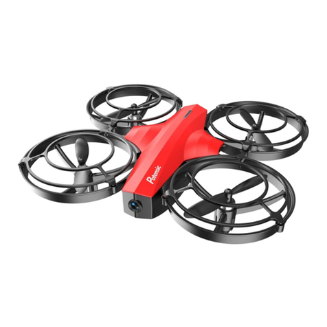
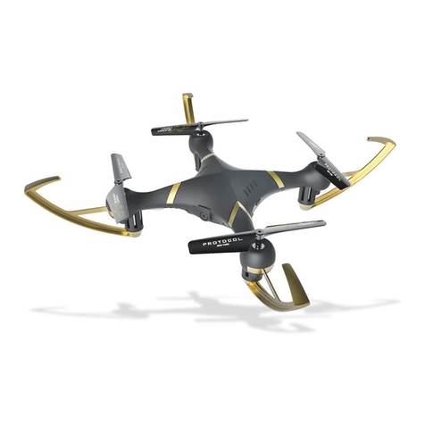
Potensic U47 User manual

Operation Guide
U47

2
Catalog
Instruction for Drone and Controller 3
Installing & Removing Spare Parts 7
Pre-Flight Checklist 10
Pre-Flight Operation Instructions 11
Functions 14
Using App 16
Spare Parts 17
Precaution about taking photos 16
Troubleshooting 19

3
Propeller A
Power Switch
Propeller B
Left Protection
Ring
Propeller B
Propeller A
Camera
Drone Battery
Front LED
(Green)
Front LED
(Green)
Drone Bottom
Housing
Rear LED
(Red)
Rear LED
(Red)
Right Protection
Ring
Drone Cover
Housing
Instruction For Drone And Controller
Drone
Left
Right
Front
Rear
Specifications
Drone Size
Drone Weight
Propeller Diameter
267x245x59mm
147g
113mm Streaming Video Range/Radius About 30m
About 50m
160~180 mins
Flying Time 8~10 mins
Drone Battery 3.7V 1000mAh
Flying Height About 15m
Charging Time for Drone Battery
Flying Distance/Radius

4
19
18
19
18
09
26
08
25
07
05
03
02
01
090807
01
07
23
24
08
12
22
05
06
05
03
10
01
21
20
19
18
19
18
16 15
08
14
13
07
12
05
11
06
05
03
10
05
06
05
04
03
02
01
06
28
17
27
Exploded View

5
No. Name No. Name
1 Propeller plug
17
2 A Propeller
18
Drone bottom Housing
3 Rotary gear
19
Landing gear lampshade
4Right rear light board
(red light/white plug)
20
Shock proof tape5 Copper cup
21
6 Motor frame
22
Lens press B
7 Main shaft steel pipe
23
lens organic plate
8 Steel pipe fixer
24
Power button
9 Propeller A motor
25
Left rear light board(red light/red plug)
10 B Propeller
Right front light board
(green light/red plug) 26
Drone cover Housing
11
Propeller B motor 27
Left front light board(green light/white plug)
28
Battery cover
Left protection ring
Right protection ring
12
Dash receiver13
Receiving plate holder14
Camera plate15
Battery adapter plate16
Controller
Power Indicator
Phone Holder Slot
Throttle Stick Direction Stick
Headless Mode
One Button Take
Off / Landing/
Emergency Stop
Button
Power Switch
Photo
Video
Notice: Taking photo and recording video are available after connecting with
smart phone.

6
Controller Button Functions
Battery Installation
Open the battery cover on the back side of the controller, insert 4 AA batteries
by following the polarity indicators. ( Picture 1/2, battery is not included)
1.Make sure the electrodes are correct. 3.Do not mix different kinds of batteries.
2.Do not mix up the new batteries with
old ones.
4.Do not charge the non rechargeable
battery.
Notice:
High/Medium/Low Speed
Mode (Press Down)
Trimmer Mode Button
(Press Down)
Alkaline Battery
Picture 1 Picture 2
Battery Cover
High / Medium / Low Speed button:
Left Stick:
Right Stick:
Power Switch:
Press to right switch to High /Medium/ Low Speed.
Move the Stick to forward / backward / left / right to fly the drone up / down / turn left / turn right.
Move the Stick to forward / backward / left / right to fly the drone forward / backward / left / right.
Trimmer Mode Button:
Press down the left stick and turn to the required trimmer direction,
then it will adjust the direction accordingly. Release the stick to exit trimmer mode.
Press the power switch to turn on the controller, and press again to turn off.
Heading Hold Mode:
Press to enter Heading Hold Mode. Press again to exit Heading Hold Mode.
Take Off / Landing / Emergency Stop Button:
automatically. Press again and the drone will land automatically. Press and hold the button for
more than 1 second for an emergency landing, the drone propellers will stop and it will land
immediately.
Press once and the drone will take off
Video:
Press down the button, start to record video.
Photo:
Press down the button, start to photograph.

7
Drone Battery
Phone Installation Instruction
Li-Po Battery Disposal & Recycling
Wasted Lithium-Polymer batteries must not be placed with household
trash. Please contact local environmental or waste agency or the
supplier of your model or your nearest Li-Po battery recycling center.
Charging Instruction for Drone Battery
Parts installation
* For faster charging, it is recommended to use an adapter with 5V 2A output current
(not included) to charge the battery
Notice:Make sure that the button on phone is not clamped.
Power BankPhone Charger Computer Charging Car Charger
1. Connect the drone battery with USB cable first and then choose one of the
methods as below picture shown to connect with USB plug.
2. The red indicator will be on while charging and the light will turn green when
the battery is fully charged.
Picture 3 Picture 4 Picture 5 Picture 6
1. Take out the phone holder and insert into the controller(Picture 3).
3. When take out the phone clip, you need to press the clip buckle behind the phone
clip at the same time, so that the buckle can be closed and removed easily.
2. Unfold the phone holder ( Picture 4/5), put the phone into the holder,
then release the clamp, and the phone will be fixed on the holder( Picture 6).

8
Aim at the
hole position
Propeller installation diagram
When installing, put the propeller hole aims to the drone shaft hole, and then press
down until bottom, tighten it with screw, and then put on propeller cover( Pic 8);
when disassembling, loose the screw and then pull out the propeller.
Notice: When installing, please make sure correct propeller in its right place,
otherwise the drone can not work well.
Picture 9
Picture 10
Picture 8
Warning: When pick up the motor, please don’t damage the LED board.
Motors Replacement Diagram
1. To remove the motor, remove the screw from the lampshade first,then take
the lampshade out, unplug the motor connector from LED board and then take
the defective motor out ( Picture 9) .
2. To install the motor, put the motor into motor holder( make sure the motor
press down and also the gears are pairing) and plug the required motor
connector into the LED board socket. Put on the motor cover and fix it with screw.
Notice: The rotation direction of the motor should be the same, or it will not work.
Tips: The motor is consumable. If it was damaged, please buy a new motor for
replacement.
After plugging in the connector, sort out
the wires according to the arrow, and
make sure the motor wires keep away
from the middle shaft.
9
When loading, aim the buckle 1 of the protection ring at the position 1 on the
bracket and push it to the bottom (Picture 11),then aim the protective ring clasp 2
at the position 2 on the bracket and press down to the right position(Picture 12).
When unloading, first pull up position 2, then pull out position 1 outwards(Picture)
Picture 11 Picture 12
Picture 13
Button Placement 1
Buckle 1
Push Here
Button Placement 2
Button Placement 2
Buckle 2Buckle 2
Diagram of loading and unloading of protective frame
When installing, push the battery to the end(Picture 14);
When disassembling,you need to squeeze up and down of the battery buckle and
just take out the battery box.
Battery installation diagram
Picture 14 Picture 15
Sticker face up
Battery buckle
Button Placement 2 Button Placement 1
Pull Outward
Force Bearing Point

10
Front
Rear
Positive / Negative wire pad
+-
Camera board socket
Pre-Flight Checklist
1. Ensure that the drone battery and controller batteries are fully charged.
2. Ensure that the left stick of the controller is in the middle position.
3. Strictly follow the instructions in sequence for turning on and turning off the
controller and drone. Turn on the controller power first and then turn on the
drone power before flying; Turn off the drone power first and then turn off the
controller power when fishing flying. Improper on/off sequence may cause the
drone to fly out of control and could threaten your safety or the safety of
others.
Please cultivate a correct habit of tturning on and turning off.
4. Ensure the connection between the battery and motor is solid. Vibration during
use may cause a bad connection and the drone could become difficult to
control.
5. Improper operation may cause the drone to crash, which may cause motor
defects affecting flying ability. If this occurs, go to the local distributor to buy
new replacement parts,so that the drone will be resorted to it's optimum status.
Receiver board wire diagram

11
Flight Instruction
Frequency Pairing
Turn on the transmitter switch and the
power indicator light flashes rapidly.
Pull the Left Stick all the way down to the lowest
position and then release. The Left Stick will back
to the middle position automatically. The power
indicator light flashes slowly, which indicates the
transmitter is ready for frequency pairing.
Press the drone power button for about 2 seconds to power on, the LED indicator
changes from flashing to stable light, the drone is paired successfully and ready
to control.( Transmitter beep sound)
It’s a must to put the drone on
the horizontal position !!!
Power switch (Press down)
Take Off
Landing
After code pairing successful, press the Take Off / Landing / Emergency
Stop Button, the drone will fly up automatically and keep flying at an
altitude of 1.2 meters approximately.
When flying, press the Take Off / Landing /
Emergency Stop Button once shortly, and the
drone will land on the ground automatically.
(When using this function, do not touch the
left stick, otherwise the function will fail)

12
After code pairing, Push the right stick as picture shown. (Don’t move the left stick before
successful calibration), the drone body light will flash 3 times, indicating that the drone is
calibrating. After successful calibration, the drone lights will become solid and ready to fly.
Tips: Crashing the drone may cause it imbalances, which can be adjusted by
the trimmer button. If this occurs, you can degrees & re-calibrate.
Emergency Stop
When the drone is in emergency situation and going to hit the walking people or
obstacle etc., press the Take Off / Landing / Emergency Stop Button immediately
and hold it for more than 1s,the propellers will stop immediately.
Tip: Do not use the emergency stop function unless in emergency situation.
The drone will fall down suddenly after all propellers stop.
Unlock/lock the motors
Unlock the motors: Push left/right stickers inward 45 degrees at the same time.
Lock the motors: When the motors are running, this operation will cause the
motors stop running immediately.
Drone calibration
(Only take this action when abnormal flying)

13
Flying Control
Left and right turning trimmer
When taking off, if the drone head rotates to left,then press down the trimmer button and push the left
stick to right. Otherwise push to left.
Forward and backward trimmer
When taking off, if the drone tilts forward, press
down the trimmer button, and push the right
stick backwards. Otherwise push forwards.
Left and right side flying trimmer
When take off, if the drone tilts to left, then press
down the trimmer button and push the right stick
backwards to adjust. Otherwise push forwards.
Trimmer mode
Left Stick
Move the stick to the left,
then the drone turns to left.
Move the stick to the right,
then the drone turns to right.
Push up the stick, then
the drone flies up.
Pull down the stick, then
the drone goes down.
Right Stick
Push up the stick, then
the drone flies forward.
Pull down the stick,
then the drone
goes backward.
Move the stick to the left,
then the drone turns to left.
Move the stick to the right,
then the drone turns to right.

14
Functions Introduction
Altitude Hold Mode
Note: If the propeller is deformed or damaged, Altitude Hold Mode will fail. If
the atmospheric pressure was instability or in typhoon weather, Altitude
Hold Mode will not work well.
Intelligent flight control system is able to calculate the hovering position, more stable
control feature, and makes it easier for beginners to control. Release the stick, the
drone will keep hovering automatically to enable single hand operation and more
clearly aerial photography.
Press down this button,then it will sound “ di”, which means low speed mode
“L”; when it sounds “ di.di”, it means medium speed “M”; and when it sounds“
di.di.di” it means high speed mode “H”.(Low speed default)
High / Medium/Low Speed Mode Switch
1. Low Speed Mode(Mode 1)
Low Speed Mode is suitable for beginner.
2. Medium speed Mode(Mode 2)
Medium Speed Mode is suitable for skillful pilots
to play in the gentle breeze.
3. High Speed Mode(Mode 3)
High Speed Mode is suitable for expert to
experience aerial stunt outdoor.
High / Medium/Low Speed
button(press down)

15
The default setting is NOT Heading hold Mode.
Drones generally have a front and rear indicated by LED lights or colored
propellers. By default, the users are required to tell the front and the rear of the
drone when flying. Under heading hold mode, the users can operate the drone
without worrying about the orientation (left is left and right is right all the time,
regardless of where your drone is pointing at).Heading Hold Mode is designed for
beginners and the users who fly the drone in daylight or at a far distance or
have difficulty to identifying the drone orientation.
Heading Hold Mode
You are allowed to activate the heading hold mode function before taking off or in
flight. Fly under heading hold mode, you’re required to ensure the drone front
direction aligned with your front direction, DO NOT change your direction of your
transmitter and keep it fly in front of you all the time.(See below picture)
WARNING: DO NOT USE HEADING HOLD MODE BEFORE YOU ARE SURE THAT
THE DRONE'S FRONT IS YOUR FRONT. OTHERWISE, IT MIGHT BE
OUT OF CONTROL OR FLY AWAY.
*Press the Heading Hold Mode button. The drone’s LED lights will flash
alternatively, indicating that the drone has entered Heading Hold Mode.
To turn off Heading Hold Mode, press the Heading Hold Mode button again.
The drone’s LED lights turn solid, indicating that Heading Hold Mode is off.
Heading Hold Mode
Front
Rear
Left Right
Front
Rear
Left Right

16
Low Battery Alarm
When the transmitter in low battery, the transmitter will beep “di...di...di...” to
remind the user to land the drone to replace the batteries as soon as possible.
Or the drone may be out of control.
When the drone in low battery, the transmitter will beep” di.di.di...” constantly to
remind the user to land the drone as soon as possible.
Out of Range Alarm
When the drone is going to fly out of the max remote control distance, the
transmitter will beep “didi...didi...didi...” to alarm the user to fly back the drone
immediately. Or the drone may be out of control and fly away.
Motors Stuck Protection
1. When the propellers get stuck, then the drone LED will flash quickly and
activate stuck protection function and the motors stop running.
2. Pull down the left stick to the lowest position, the drone LED will get a solid
light and stuck protection will be released and the drone can fly again.
Download and install APP: Potensic
This software is suitable for mobile phones in the IOS and Android system,
please surf the mobile phone application store website to download and install it.
1. The user of IOS mobile phone can surf App Store to
search Potensic to download.
2. The user of Android can surf Google Play to search
Potensic to download.
3. You can scan the QR code on the right or the QR
code on the color box directly to download and install it.
4. For detailed operation, please check the system “HELP” of APP.
Know your APP
Display the photos and video
Notice: App must be authorized to access the phone gallery, if not, then may
be unavailable to display the video and photos.
The photos and videos are stored in the phone local gallery, you can display
them in the phone directly. You also can display it in the APP through
shortcut icon to enter the media interface.

17
Spindle Steel Pipe Copper ring Transmission Gear A propeller motor
( Black white wire/
white connector)
Drone Cover
Housing
Drone Bottom
Housing
A Propeller B Propeller
Left protection ring Right protection ring Landing gear
lampshade
Motor Holder
Receiver Board Holder Power Button Cushion Steel Pipe Fixings
Spare Parts
These are the components for choice below. For your convenient purchase, now
we list each part for you, you can purchase ones you want from local distributor.
(Sold separately)

18
B propeller motor
( Red blue wire/
red connector)
Left Front Lamp
Board (Green LED /
White Connector)
Right Front Lamp
Board (Green LED /
Red Connector)
Right Rear Lamp
Board (Red LED /
White connector)
Left Rear Lamp
Board (Red LED /
Red connector)
Receiver Board Camera Board Drone Battery
USB Cable Screw Driver Smart Phont Holder Transmitter
Important Notice
Since our company's products have been improving all the time,subject design
and specifications are change without notice.
All the information in this manual has been carefully checked to ensure accuracy,
if any printing errors, our company reserve the final interpretation right.

19
The
controller
indicator
light is off.
The drone
is under-
powered
or can not
fly.
The drone
could not
hover and
tilts to one
side.
1
3
4
Problem Problem Cause SolutionNo.
1. Low battery. 1. Replace the controller battery.
2. The batteries are incorrectly
positioned.
2. Install the batteries following the
polarity indicators.
3. Poor Contact. 3. Clean between the battery and the
battery contacts.
1. Indicator light is o. 1. The same as above.
2. There is an interfering signal nearby.
2. Restart the drone and power on the
controller.
3. Improper operation. 3. Operate the drone step by step in
accordance with the user manual.
4. The electronic component is
damaged for ercely crash.
4. To buy spare parts from local seller
and replace damaged parts.
1. The propeller is seriously deformed. 1. Replace the propeller.
2. Low battery. 2. Recharge the drone battery.
3. Incorrect installation of propeller. 3. Install the propeller in accordance
with the user manual.
2. The propeller is seriously deformed. 2. Replace the propeller.
3. The motor holder is deformed after
violent crash. 3. Replace the motor holder parts.
1. Improper Calibration. 1. Please refer to the Calibration
Instruction.
4. The gyroscope did not reset after a
serious crash.
4. Put the drone on the at ground for
about 10s or restart the drone to
calibrate again.
Failed to
pair the
drone with
the
controller.
2
The drone
indicator
light is off.
Could not
see the
picture.
5
6
1. Low battery. 1. Recharge the drone battery.
5. Motor is damaged. 5. Replace the motor.
2. The battery is expired or over
discharge protection.
2. Buy a new battery from local seller
to replace the battery or charge the
battery in accordance with the use
manual.
3. Poor contact. 3. Connect and disconnect the battery.
1. There is an interfering signal nearby. 1. Practice and read the cellphone
controlling instruction carefully.
2. Camera is damaged. 2. Replace Camera.
Hard to control by
cellphone.
7Not experienced enough. Practice and read the cellphone
controlling instruction carefully.
Can’t
altitude
hold.
8
1. The propeller deformed seriously. 1. Replace propeller.
2. The motor is damaged. 2. Replace the motor.
3. Atmospheric pressure is not stable.
3. Refer the altitude hold mode of use
manual .
Troubleshooting

20
MADE IN CHINA
FCC Note
This equipment has been tested to comply with the limits for a Class B
digital device, pursuant to Part 15 of the FCC Rules. These limits are designed to
provide reasonable protection against harmful interference in a residential
installation. This equipment generates uses and can radiate radio frequency
energy, if not installed and used in accordance with the instructions, which may
cause harmful interference to radio communications. However, there is no
guarantee that interference will not occur in a particular installation. If this
equipment does cause harmful interference to radio or television reception,
which can be determined by turning the equipment off and on, the user is
encouraged to try to correct the interference by one or more of the following
measures:
●Reorient or relocate the receiving antenna.
●Increase the separation between the equipment and receiver.
●Connect the equipment into an outlet on a circuit different from that to which
the receiver is connected.
WARNING: Changes or modifications not expressly approved by the party
responsible for compliance could void the user's authority to
operate the equipment.
This device complies with Part 15 of the FCC Rules. Operation is subject to the
following two conditions:
(1) This device may not cause harmful interference.
(2) This device must accept any interference received, including interference that
may cause undesired operation.
The equipment may generate or use radio frequency energy. Changes or
modifications to this equipment may cause harmful interference unless the
modifications are expressly approved in the instruction manual. Modifications not
authorized by the manufacturer may void user’s authority to operate this device.
FCC Notice:
The device has been evaluated to meet general RF exposure requirement.
The device can be used in portable exposure condition with out restriction.
FCC Radiation Exposure Statement
Table of contents
Other Potensic Drone manuals

Potensic
Potensic Dreamer Mini User manual

Potensic
Potensic D88 User manual

Potensic
Potensic ATOM SE User manual

Potensic
Potensic Dreamer Mini User manual

Potensic
Potensic Wisp User manual

Potensic
Potensic A30 User manual

Potensic
Potensic ATOM SE User manual

Potensic
Potensic D60 User manual

Potensic
Potensic T25 User manual

Potensic
Potensic Dreamer 1 User manual