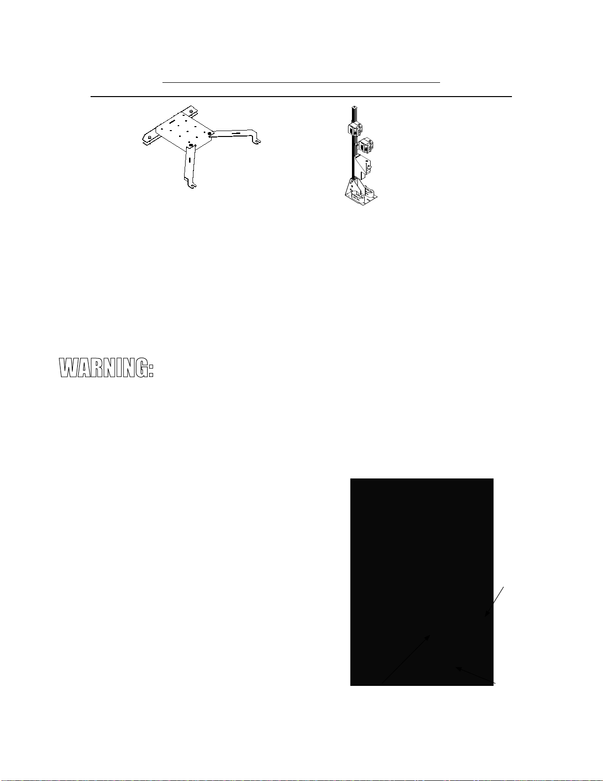
Self-Supporting Mounting Base
G8116FT
pro-gard.com
800.480.6680
6
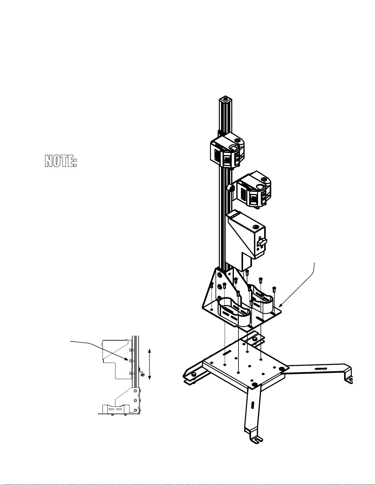
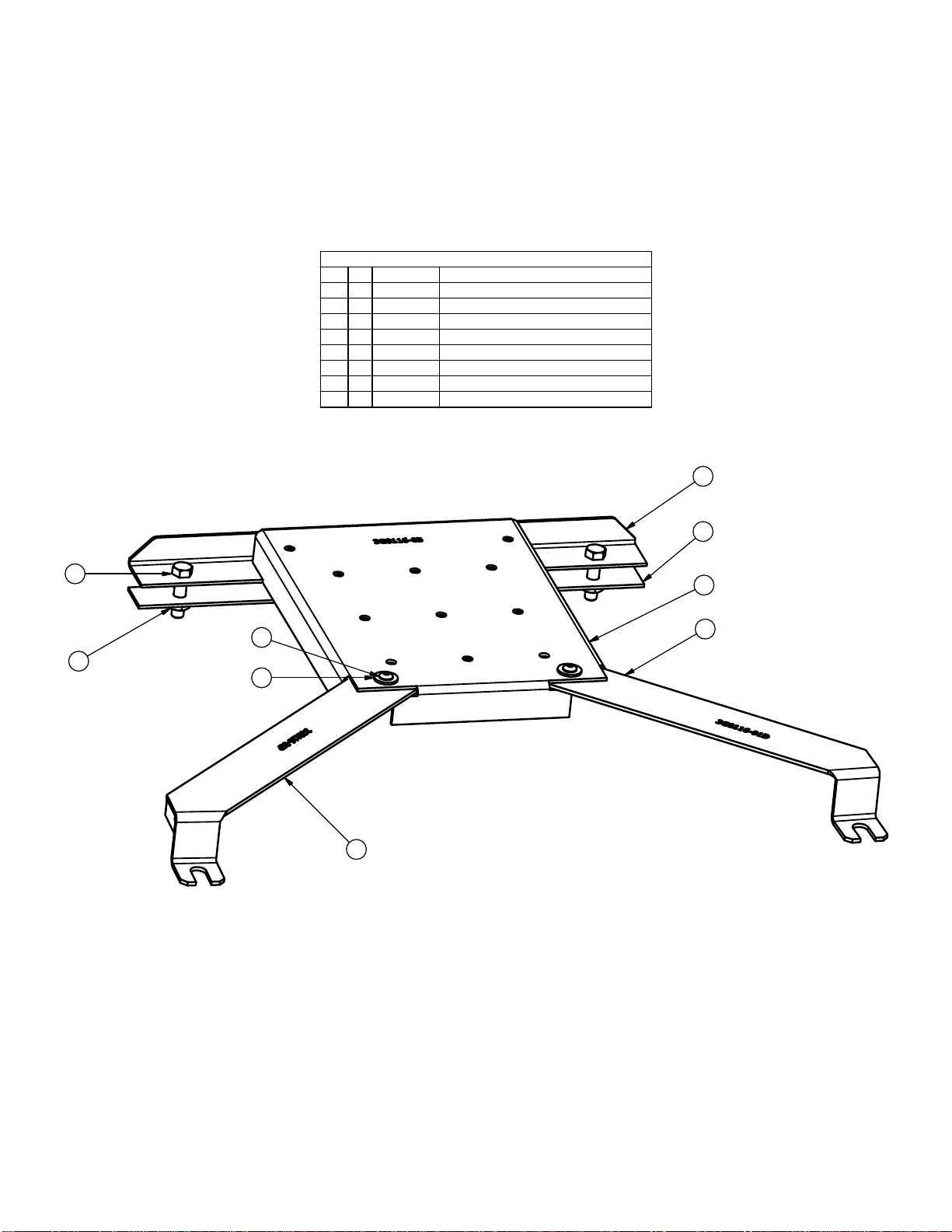
PARTS LIST
DESCRIPTIONPART NUMBERQTYITEM
BRACE, BASE REAR F-1503G8116-0611
SUPPORT ARM ASSY, DS3G8116-01D12
SUPPORT ARM ASSY, PS3G8116-01P13
3/8-16x1.50, Hex Tap Bolts, Grade 8, Yellow Zinc3X11924
UNDERBRACE ASSY, F-1503G8116-021
5
F-150 BASE PLATE ASSEMBLY3G8116-0316
1/4 FLAT WASHER, BLACK
12
1/4-20x0.75, SBHCS, BLACK OXIDE
184
68
1
1
2
2
3
3
4
4
A A
B B
C C
D D
Products, LLC
7988 Centerpoint Dr., Suite 400
Indianapolis, IN 46256
(317) 579-6680
PART DESCRIPTION:
DRAWN BY:
SCALE:
CHECKED BY:
DATE:
APPROVED:
UNLESS OTHERWISE SPECIFIED :
The information contained herein is
proprietary and the property of Pro-gard
Products and may not be reproduced,
disclosed or used for any other purpose other
than a quotation to or an order from
Pro-Gard Products without the specific
written authorization of Pro-gard Products. Computer Path:
SIZE: A
ENGR 1:
ENGR 3:
ENGR 2:
FINAL:
PRODUCTION:
Third
Angle
Projection
DIMENSIONS ARE IN INCHES
TOL ON 3 PLACE DECIMALS: .005
DIMENSIONS ARE IN INCHESTOL ON ANGLES 1°
TOL ON 2 PLACE DECIMAL .015
NOTE:
MATERIAL:
FINISH:
STAMP: ASSEMBLY NO: DRAWING NO:
SHEET:
REV:
APPL:
Pro-gard
EICHHORN
2-26-16
SELF SUPPORTING GUN RACK BASE ASSY, F-150
2015 F-150 BASE
4GVM8116FT
NTS 1
FREE OF SHARP EDGES
4G8116 0
V:\All Product Line\Gun Racks\GVM Self Supporting\FORD F150\2015\4GVM8116FT.iam
REVISION HISTORY
REV SHEET DESCRIPTION AUTHOR DATE
0 ALL NEW RELEASE EICHHORN 1/26/2016
1
5
2
6
3
4
5
8
7
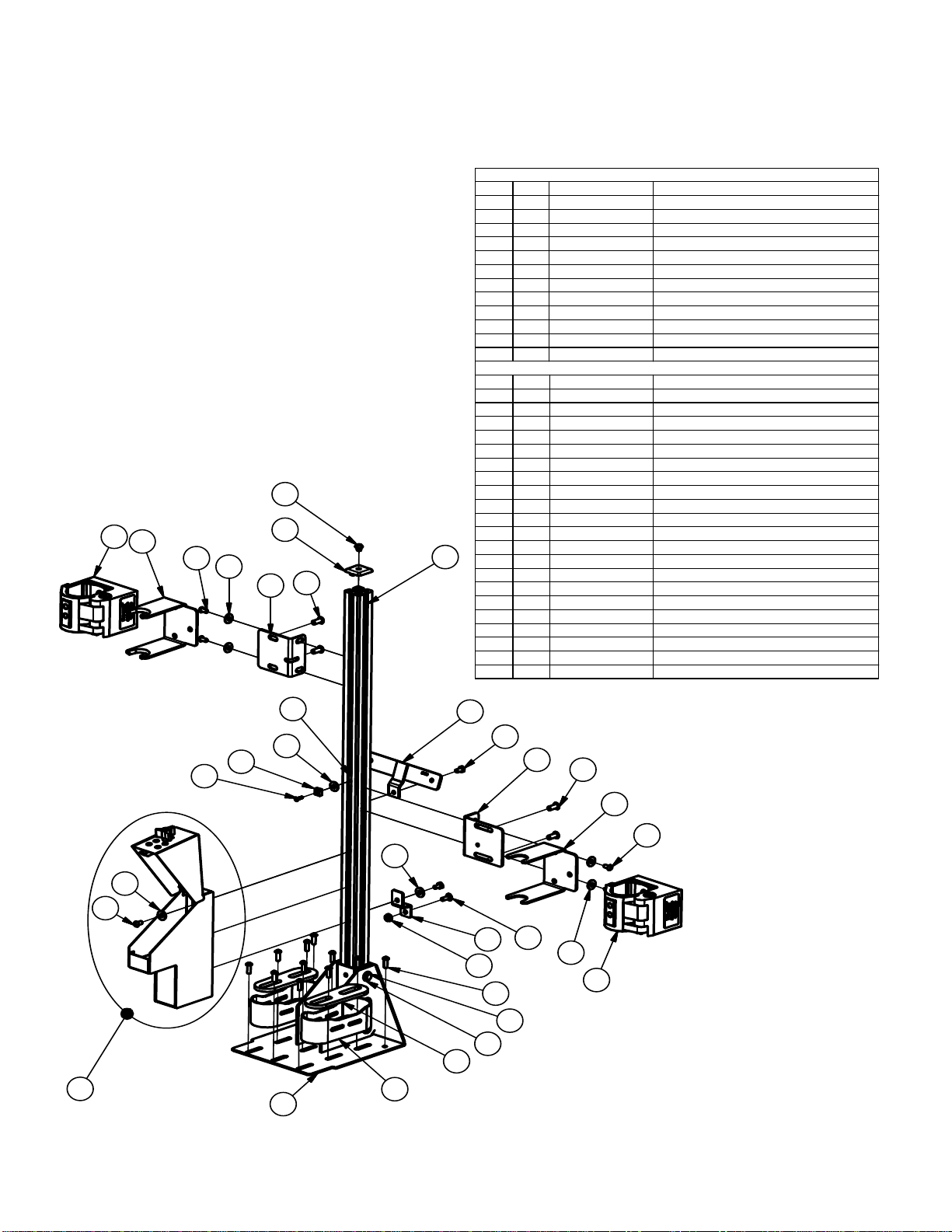
PARTS LIST
DESCRIPTIONPART NUMBERQTYITEM
BRACE, BASE REAR F-1503G8116-0611
SUPPORT ARM ASSY, DS3G8116-01D12
SUPPORT ARM ASSY, PS3G8116-01P13
3/8-16x1.50, Hex Tap Bolts, Grade 8, Yellow Zinc3X11924
UNDERBRACE ASSY, F-1503G8116-021
5
F-150 BASE PLATE ASSEMBLY3G8116-0316
1/4 FLAT WASHER, BLACK3X126
7
1/4-20x0.75, SBHCS, BLACK OXIDE3X18468
1
1
2
2
3
3
4
4
A A
B B
C C
D D
Products, LLC
7988 Centerpoint Dr., Suite 400
Indianapolis, IN 46256
(317) 579-6680
PART DESCRIPTION:
DRAWN BY:
SCALE:
CHECKED BY:
DATE:
APPROVED:
UNLESS OTHERWISE SPECIFIED :
The information contained herein is
proprietary and the property of Pro-gard
Products and may not be reproduced,
disclosed or used for any other purpose other
than a quotation to or an order from
Pro-Gard Products without the specific
written authorization of Pro-gard Products. Computer Path:
SIZE: A
ENGR 1:
ENGR 3:
ENGR 2:
FINAL:
PRODUCTION:
Third
Angle
Projection
DIMENSIONS ARE IN INCHES
TOL ON 3 PLACE DECIMALS: .005
DIMENSIONS ARE IN INCHESTOL ON ANGLES 1°
TOL ON 2 PLACE DECIMAL .015
NOTE:
MATERIAL:
FINISH:
STAMP: ASSEMBLY NO: DRAWING NO:
SHEET:
REV:
APPL:
Pro-gard
EICHHORN
2-26-16
SELF SUPPORTING GUN RACK BASE ASSY, F-150
2015 F-150 BASE
4GVM8116FT
NTS 1
FREE OF SHARP EDGES
4G8116 0
V:\All Product Line\Gun Racks\GVM Self Supporting\FORD F150\2015\4GVM8116FT.iam
REVISION HISTORY
REV SHEET DESCRIPTION AUTHOR DATE
0 ALL NEW RELEASE EICHHORN 1/26/2016
1
5
2
6
3
4
5
8
7