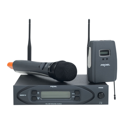
PROEL RM100 User manual

RM100
Wireless System

2
RM100
INDICE
Precauzioni d’uso .........................................................................................................................................................3
Descrizione ....................................................................................................................................................................5
Ricevitore RM100 (fig.1) .............................................................................................................................................5
Trasmettitore a mano WTX201 (fig. 2) .......................................................................................................................5
Trasmettitore body ack WHX21 (fig.3) ......................................................................................................................6
INDEX
Safety Instructions...................................................................................................Errore. Il segnalibro non è definito.
Description.....................................................................................................................................................................9
Available Frequencies ................................................................................................................................................9
Receiver RM100 (fig.1)...............................................................................................................................................9
Transmitter WTX201 (fig. 2) .......................................................................................................................................9
Body ack WHX21 (fig.3) .........................................................................................................................................10
Disegni / Dra ings ......................................................................................................................................................11
FIG.1 - Receiver RM100...........................................................................................................................................11
FIG.2 - Transmitter WTX201 ....................................................................................................................................12
FIG.3 - Body ack WHX21 ........................................................................................................................................12
Caratteristiche Tecniche – Technical Specifications ..............................................................................................13

3
RM100
Precauzioni d’uso
AVVERTENZA: Per ridurre il rischio di folgorazione, non rimuovere il co erchio (o il annello osteriore). All’interno non sono contenute arti
ri arabili dall’utente; affidare la ri arazione a ersonale qualificato.
ATTENZIONE: Per ridurre il rischio d’incendio o di folgorazione, non es orre questo a arecchio alla ioggia o all’umidità.
Questo simbolo, ove com are, segnala la resenza di un voltaggio ericoloso non isolato all’interno del cor o dell’a arecchio,
voltaggio sufficiente a costituire un rischio di folgorazione.
Questo simbolo, ove a are, segnala im ortanti istruzioni d’uso e manutenzione nel testo allegato. Leggere il manuale.
RACCOMANDAZIONI
Tutte le istruzioni di sicurezza e funzionamento devono essere lette rima di mettere in funzione l’a arecchio.
Conservare le istruzioni
Le istruzioni di sicurezza e di funzionamento devono essere conservate er un futuro riferimento.
Il resente manuale è arte integrante del rodotto e lo deve accom agnare in caso di eventuali cambi di ro rietà. In questo modo il nuovo
ro rietario otrà conoscere le istruzioni relative a installazione, funzionamento e sicurezza.
Prestare attenzione
Tutte le avvertenze sull’a arecchio e nelle istruzioni di funzionamento devono essere seguite fedelmente.
Osservare tutti gli avvertimenti.
Seguire le istruzioni:
Tutte le istruzioni er il funzionamento e er l’utente devono essere seguite.
Le note recedute dal simbolo contengono im ortanti informazioni sulla sicurezza: leggerle con articolare attenzione.
ISTRUZIONI DI SICUREZZA IN DETTAGLIO
Acqua ed umidità
L’a arecchio non deve essere utilizzato in rossimità di acqua ( er es. vicino a vasche da bagno, lavelli da cucina, in rossimità di iscine ecc.).
Calore
L’a arecchio deve essere osto lontano da fonti di calore come radiatori, termostati, asciuga biancheria, o altri a arecchi che roducono calore.
Alimentazione
• L’a arecchio deve essere collegato soltanto al ti o di alimentazione descritto nelle istruzioni d’uso o segnalato sull’a arecchio.
• Se la s ina in dotazione non combacia con la resa, rivolgersi ad un elettricista er farsi installare una resa a ro riata.
Messa a terra o polarizzazione
• Si devono rendere recauzioni in modo tale che la messa a terra e la olarizzazione dell’a arecchio non siano regiudicate.
• Le arti metalliche dell’a arecchiatura sono collegate a massa tramite il cavo d’alimentazione.
• Se la resa utilizzata er alimentazione non ossiede collegamento a massa, rivolgersi ad un elettricista qualificato er fare collegare
l’a arato a massa tramite il terminale.
Protezione del cavo di alimentazione
Il cavo di alimentazione elettrica deve essere installato in modo che non venga cal estato o izzicato da oggetti osti so ra o contro, restando
articolare attenzione a cavi e s ine, rese a muro.
Pulizia
• Quando l’unità deve essere ulita, è ossibile eliminare la olvere utilizzando un getto d’aria com ressa o un anno inumidito.
• Non ulire l’unità utilizzando solventi quali trielina, diluenti er vernici, fluidi, alcol, fluidi ad alta volatilità o altri liquidi infiammabili.
Periodi di non utilizzo
Il cavo di alimentazione dell’a arecchio deve essere staccato dalla resa se rimane inutilizzato er un lungo eriodo.
Ingresso di liquidi o oggetti
Fare attenzione a far cadere oggetti e o liquidi nel cor o dell’a arecchio.

4
RM100
Uso sicuro della linea d’alimentazione
• Quando si scollega l’a arato alla rete tenere saldamente sia la s ina che la resa.
• Quando l’unità non viene utilizzata er un eriodo rolungato, interrom ere l’alimentazione estraendo la s ina dalla resa
dell’alimentazione.
• Per evitare danni alla linea d’alimentazione dell’a arato, non mettere in trazione il cavo d’alimentazione e non utilizzare un cavo
attorcigliato.
• Per evitare il danneggiamento del cavo d’alimentazione dell’a arato, assicurarsi che questo non venga cal estato o schiacciato da
oggetti esanti.
Spostamento dell’unità
Prima di ogni s ostamento, verificare che l’unità sia s enta. Il cavo d’alimentazione deve essere estratto dalla resa, così come i collegamenti
dell’unità con altre linee.
Non smontare l’unità
Non tentare di smontare né ri arare da soli l’unità. Per qualsiasi roblema non risolvibile con l’aiuto del resente manuale, rivolgersi a un tecnico
qualificato o consultare la nostra com agnia. Qualsiasi uso non a ro riato uò causare incendi o scosse elettriche.
Malfunzionamenti
• Non tentare mai di eseguire ri arazioni diverse da quelle descritte nel resente manuale.
• Contattare un centro di servizio autorizzato o del ersonale altamente qualificato nei seguenti casi:
- Quando l’a arato non funziona o funziona in modo anomalo.
- Se il cavo d’alimentazione o la s ina sono danneggiati.
- Sono enetrati oggetti estranei o è stato versato del liquido nell’a arecchio.
- L’a arecchio è stato es osto alla ioggia.
- L’a arecchio non sembra funzionare normalmente o resenta un evidente cambiamento nelle restazioni.
- L’a arecchio è caduto, o il cor o è danneggiato.
Manutenzione
L’utente non deve tentare di ri arare l’a arecchio al di là di quanto descritto nelle istruzioni di funzionamento. Ogni altra ri arazione deve essere
affidata a ersonale s ecializzato.
IMPORTANTI NORME DI SICUREZZA
• Installare seguendo le istruzioni.
• Il voltaggio d’alimentazione dell’unità è abbastanza elevato: er evitare il rischio di scosse elettriche, non installare, collegare o
sconnettere l’alimentazione quando l’a arato è acceso.
• Non a rire mai l’a arecchiatura: all’interno non esistono arti utilizzabili dall’utente.
• Se si avverte uno strano odore roveniente dall’a arato, s egnerlo immediatamente e sconnettere il cavo dell’alimentazione.
• Non ostruire le griglie di ventilazione dell’a arato.
• Evitare che l’unità lavori in sovraccarico er tem o rolungato.
• Non forzare i comandi ( ulsanti, controlli, ecc.).
• Per ragioni di sicurezza, non annullare il collegamento a massa della s ina. Il collegamento a massa è necessario er
salvaguardare la sicurezza dell’o eratore.
• Utilizzare unicamente i connettori e gli accessori s ecificati dal roduttore.
• In resenza di tem orali con fulmini o quando l’a arato non è utilizzato, estrarre la s ina d’alimentazione dalla resa.
• Per revenire il rischio di incendi e scosse elettriche, è necessario tenere l’a arato lontano da s ruzzi e gocce. So ra l’a arato
non devono essere collocati vasi o altri oggetti contenenti liquidi. In caso si verifichino interferenze nel circuito di rovenienza, il valore
di THD sarà su eriore al 10%. Non installare questo a arato in una libreria o in altri luoghi a s azio ristretto.
• PROEL S. .A. declina ogni res onsabilità in caso di scorretta installazione dell’unità..

5
RM100
Grazie er aver scelto un rodotto PROEL e della fiducia ri osta nel nostro marchio, sinonimo di rofessionalità, accuratezza, elevata qualità ed
affidabilità. Tutti i nostri rodotti sono conformi alle normative CE er utilizzazione continua in im ianti di diffusione sonora.
Descrizione
I radiomicrofoni serie RM100 sono sistemi VHF a singola frequenza controllata al quarzo, caratterizzati da una trasmissione affidabile e di ottima
qualità.
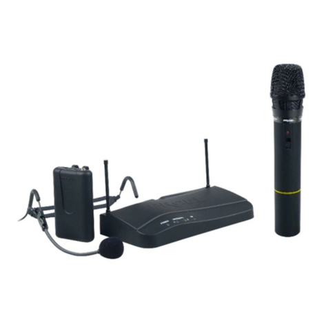
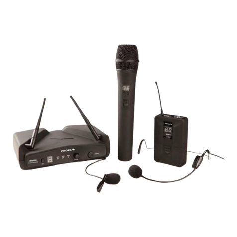
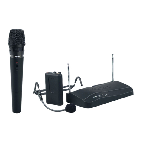
Il sistema radio microfonico RM100 è com osto da 3 arti: ricevitore RM100, trasmettitore a mano WTX201 e trasmettitore tascabile WHX21. Il
sistema è dis onibile in 5 diverse configurazioni, ognuna dotata di una valigetta in ABS er il tras orto:
RM100M: RM100 + WTX21 (microfono a mano)
RM100H: RM100 + WHX21 + HCM2 (microfono Headset HCM2)
RM100L: RM100 + WHX21 + LCM1 (microfono Lavalier LCM1)
RM100G: RM100 + WHX21 + LS01 (cavo chitarra/basso)
RM100KIT: RM100 + WHX21 + HCM2 + LCM1 + LS01 + WTX21)
Sono dis onibili sette frequenze diverse resettate in fabbrica:
1. 175.500 MHZ
2. 179.300 MHZ
3. 181.900 MHZ
4. 184.320 MHZ
5. 197.320 MHZ
6. 200.320 MHZ
7. 207.320 MHZ
Ricevitore RM100 (fig.1)
1. Spia Po er
L’accensione della s ia indica che l’a arecchio è in funzione.
2. Spia RF
La s ia accesa segnala la ricezione del segnale.
3. Spia AF
L’accensione della s ia indica il raggiungimento del livello limite oltre il quale ha inizio una distorsione del segnale.
4. Antenna
5. Volume / Po er
Potenziometro con interruttore er l’accensione e controllo volume.
6. Audio Out
Uscita segnale audio sbilanciato er il collegamento all’am lificatore.
7. DC IN
Connettore er il collegamento dell’adattatore 12V dc.
8. Controllo squelch
Trimmer che consente di regolare la soglia del circuito riduzione del rumore. Per la regolazione utilizzare un iccolo cacciavite iatto.
9. Tabella
Indicazione della frequenza del ricevitore.
Trasmettitore a mano WTX201 (fig. 2)
1. Griglia
Protegge la ca sula microfonica
2. Interruttore di accensione
L’interruttore ossiede 3 osizioni: s ento - acceso – mute. L’accensione della s ia er un istante indica lo stato di carica della batteria.
In caso di mancata accensione della s ia occorre sostituire la batteria.
3. Coperchio vano batteria
Svitando il co erchio è ossibile accedere al vano contenente la batteria da 1.5V. Al suo interno è indicata la frequenza del
trasmettitore.

6
RM100
Trasmettitore bodypack WHX21 (fig.3)
1. Bat.Lo
L’accensione della s ia er un istante indica che la batteria da 9 Volt è carica. In caso di mancata accensione della s ia occorre
sostituire la batteria.
2. Interruttore di accensione
L’interruttore ossiede 3 osizioni: s ento - acceso – mute. L’accensione della s ia er un istante indica lo stato di carica della batteria.
3. Controllo volume
Regola il volume d’uscita del trasmettitore.
4. Ingresso audio
Ingresso mini jack da 3,5mm er il collegamento al trasmettitore del trasduttore fornito in dotazione a seconda del modello (hcm2, lcm1
o cavo chitarra).
5. Selettore Sens
Seleziona tre sensibilità di ingresso:
a. osizione 1 = segnali Linea ( Chitarra / basso)
b. osizione 2 = microfono HEADSET (dinamico)
c. osizione 3 = microfono LAVALIER (a condensatore)
6. Vano batteria
Sollevando il co erchio è ossibile accedere al vano contenente la batteria da 9V. Al suo interno è indicata la frequenza del
trasmettitore.
AVVERTENZA
Questo a arecchio radio è inteso er uso rofessionale soggetto all’ottenimento di una “autorizzazione generale”, nell’ambito
dell’intrattenimento e a licazioni similari.
Questo a arecchio otrebbe essere in grado di funzionare a frequenze non autorizzate nella regione in cui si trova l’utente. Si
consiglia di rivolgersi alle autorità com etenti er ottenere le informazioni necessarie relative alle frequenze autorizzate nella
ro ria regione er i sistemi radiomicrofonici.
In alcuni casi otrebbe essere necessaria una licenza ministeriale er l’uso di questo a arecchio. Per i ossibili requisiti
rivolgersi alle autorità com etenti.
L’utente si assume l’esclusiva res onsabilità er l’acquisizione della licenza delle attrezzature senza fili e la licenziabilità di ende
dalla classificazione e dall’a licazione dell’utente e dalla frequenza selezionata.
Il rodotto è conforme alla Direttiva 89/336/CEE (Com atibilità Elettromagnetica) e successive modifiche 92/31/CEE e
93/68/CEE. Inoltre, è conforme alla Direttiva 73/23/CEE (Bassa Tensione) e successive modifiche 93/68/CEE.
Con la resente Proel S. .A. dichiara che questo sistema radiomicrofonico è conforme ai requisiti essenziali ed alle altre
dis osizioni ertinenti stabilite dalla direttiva 1999/5/CE. A arecchio notificato in Italia (D.lgs 269/2001). La dichiarazione di
conformità uò essere consultata sul sito: www. roelgrou .com
PROEL S. .A. Via alla Ruenia 37/43 64027 Sant’Omero (Te) – Italy Tel: +39 0861 81241 Fax: +39 0861 887862 info@ roelgrou .com
La Proel S A ersegue una olitica di costante ricerca e svilu o, di conseguenza si riserva il diritto di a ortare miglioramenti ai
rodotti esistenti, senza reavviso e in qualunque momento.
La Proel S A non assume alcuna res onsabilità sull’uso ed alle a licazioni dei rodotti o circuiti ri ortati su questo manuale.

7
RM100
Safety Instructions
CAUTION: To reduce the risk of electric shock do not the remove cover or back anel. No user serviceable arts inside. Refer servicing to
qualified ersonnel only.
WARNING: To reduce the risk of fire or electric shock, do not ex ose this a aratus to rain or moisture.
This symbol is intended to alert the user of the resence of un-insulated dangerous voltage within the roduct enclosure that may be of
sufficient magnitude to constitute a risk of electric shock to ersons.
This symbol is intended to alert the user of the resence of im ortant o erating and maintenance (servicing) instruction in the literature
accom anying the a liance. Please carefully read the owner’s manual.
INSTRUCTIONS
All safety and operating instructions should be read before the product is operated.
Retain these instructions
All safety and o erating instructions should be retained for future reference.
This owner’s manual should be considered as a art of the roduct and it must accom any it every time, and delivered to the new user when this
roduct is sold. In this way the new owner will be aware of all the installation, o erating and safety instructions.
Heed all arnings
All warnings on the roduct and in owner’s manual should be adhered to.
Follo all instructions
All o erating and user’s instructions must be followed.
Sentences receded by symbol contain im ortant safety instruction. Please read it carefully.
DETAILED SAFETY INSTRUCTIONS
Water and moisture
This a aratus should not be used near water (i.e. bathtub, kitchen sink, swimming ools, etc.).
Heat
This a aratus should be laced away from heat sources, like radiators, heat registers, stoves or other roducts (including am lifiers) that
roduce heat.
Po er sources
• This a aratus should only be connected to ower source ty e s ecified in this owner’s manual or on the unit.
• If the su lied AC ower cable lug is different from the wall socket, lease contact an electrician to change the AC ower lug.
Grounding or Polarization
• All recautions must be observed to do not defeat grounding or olarization.
• Unit metal arts are grounded through the AC ower cord.
• If the AC ower outlet doesn’t have grounding, consult an electrician for outlet grounding.
Po er cord protection
The ower cord should be ositioned in a way it will not be ste ed on or inched by items laced u on or against it, aying articular attention to
cable connected to the lugs, sockets and wall outlets.
Cleaning
• The unit can be cleaned with com ressed air or with a soft dam cloth.
• Do not clean the unit with solvents such as trichloroethylene, thinners, alcohol, or other fluids with very strong volatility and flammability.
Long periods here the unit is not being used
If not used for long eriods, the unit should be disconnected from the AC ower su ly.
Objects or liquid entry inside the unit
Be careful that no objects fall or liquid is s illed inside the unit through ventilation o enings.
Safe po er line use
• Hold the lug and the wall outlet while disconnecting the unit from AC ower.
• If the unit will not be used for a long eriod of time, lease un lug the ower cord from AC ower outlet.
• To avoid unit ower cord damage, lease do not strain the AC ower cable and do not bundle it.
• In order to avoid unit ower cord damage, lease ensure that the ower cord is not ste ed on or inched by heavy objects.
8
RM100
Unit relocation
Before the unit is relocated lease ensure the unit is switched off. The ower cord must be un lugged from the wall outlet and all connection
cables should be disconnected.
Do not open this unit
Do not attem t to o en or to re air this unit by yourself. For any roblems not described in this owner’s manual, lease refer to qualified ersonnel
only or consult PROEL or your National PROEL Distributor. Any im ro er o eration could result in fire or electric shock.
Damages requiring services
• Do not attem t any o erations not described in this user’s manual.
• In the following cases lease refer to an authorised maintenance centre or skilled ersonnel:
- When the unit works im ro erly or it does not work at all.
- If ower cord or lug are damaged.
- If liquid has s illed, or objects have fallen into the unit.
- If the unit has been ex osed to rain.
- If the unit does not o erate normally or it exhibits a marked change in erformance.
- If the roduct has been dro ed or it has been damaged in any way.
Maintenance
The user should not attem t any maintenance o eration not described in this user’s manual. All maintenance should be carried out by qualified
ersonnel.
IMPORTANT SAFETY INSTRUCTIONS
• Install this unit following owner’s manual instructions.
• Do not install, connect or disconnect ower su ly when the unit is owered, to avoid electric shock.
• Do not o en the unit: there are no user serviceable arts inside.
• If you detect any strong smell emanating from the unit, immediately turn it off and disconnect the AC ower cord.
• Do not block the unit ventilation o enings.
• Avoid using this unit in overload for a long eriod.
• Do not force the commands (switches, controls, etc.)
• For safety reason, do not defeat or by ass the grounding connection. Grounding is im ortant for user safety.
• Only use connectors and accessories suggested by the manufacturer.
• This unit should be laced in a rack and ke t far from:
- Wet / humid areas
- Direct ex osure to heat sources (like sun light)
- Non ro erly ventilated laces
• Disconnect the ower cord during storms or when the unit is not being used.
• In order to revent fire and electric shock risks, it is necessary to kee the unit far from liquids. Please do not ut cu s, vases or
other object containing liquids over the unit. In case of interference from source signal, the THD value will raise over 10%. Do not lace
this unit in confined s aces.
• PROEL S. .A. is not res onsible for any damage that occurs due to a incorrect installation of the unit.

9
RM100
Thank you for choosing this PROEL roduct and for your trust in our brand, synonymous of rofessionalism, accuracy, high quality and
reliability. All our roducts are CE a roved and designed for continuous use in rofessional systems.
Description
The RM100 wireless micro hones series is a VHF, quartz controlled, fixed frequency device, which rovides a reliable, high quality signal
transmission.
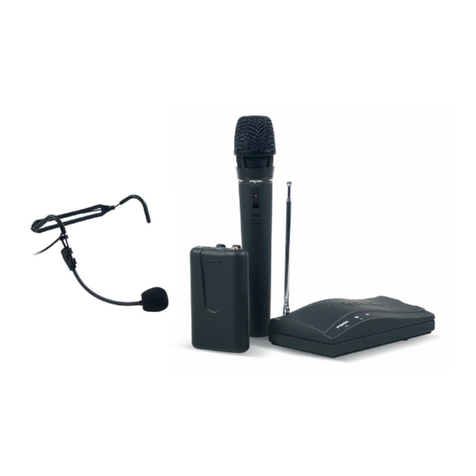
RM100 Wireless Micro hone system features 3 units: RM100 receiver, WTX201 Handheld transmitter and WHX21 body ack transmitter.
The system is available in five different configurations, each of them including an ABS carrying case:
RM100M: RM100 + WTX21 (Handheld microphone)
RM100H: RM100 + WHX21 + HCM2 (Headset HCM2)
RM100L: RM100 + WHX21 + LCM1 (Lavalier LCM1)
RM100G: RM100 + WHX21 + LS01 (guitar / bass cable)
RM100KIT: RM100 + WHX21 + HCM2 + LCM1 + LS01 + WTX21)
Available Frequencies
1. 175.500 MHZ
2. 179.300 MHZ
3. 181.900 MHZ
4. 184.320 MHZ
5. 197.320 MHZ
6. 200.320 MHZ
7. 207.320 MHZ
Receiver RM100 (fig.1)
1. Po er On LED
This LED lights u when the receiver is switched on.
2. LED RF
This LED lights u when RF signal is received.
3. LED AF
This LED lights u when the audio signal of the wireless micro hone is close to cli ing.
4. Volume / Po er
Power switch and level control.
5. Audio Out
Unbalanced audio out ut with ¼ inch JACK lug.
6. DC IN
Connect AC/DC ower su ly to VDC after having connected the lug to main ower su ly 220-230Vac.
7. Squelch control
The squelch control is factory reset in order to achieve best erformance in most a lications.
8. Frequency label
Label with the transmitter o erating frequency.
Transmitter WTX201 (fig. 2)
1. Microphone Head
Grille for micro hone ca sule rotection.
2. Po er S itch
This 3- osition selector (ON/OFF/MUTE) allows to switch ON or OFF the transmitter and to MUTE the micro hone.
3. Battery
Unscrewing the cover, you can access the 1.5V battery rece tacle. Here inside you can find the transmitter frequency.

10
RM100
Bodypack WHX21 (fig.3)
1. Bat.Lo
Turning on the transmitter, this LED lights u for a while to indicate that the battery is charged and the transmitter is working
ro erly. When the battery charge level is too low, thus not allowing a ro er signal transmission, this LED is constantly lighted,
in this condition we suggest you immediately re lace the battery.
2. Po er Selector
This 3 osition selector allows to turn on/off the transmitter, as well as to activate/deactivate the audio source connected to Mic
in ut. Batt.lo LED should turn on for a while.
3. Volume Control
This control allows the user to adjust transmitter volume, and to ada t it to in ut signal of different sensitivity.
4. Mic In Input
5. This 3,5 mm jack allows the connection an audio source to be transmitted.
6. Sens Selector
This selector allows the user to select three sensitivity levels:
• osition 1 = Line ( guitar / bass)
• osition 2 = HEADSET (dynamic)
• osition 3 = LAVALIER (condenser)
7. Battery Older
Unscrewing the cover, you can access the alkaline 9V battery rece tacle, useful for transmitter o eration.
WARNING
LICENSING INFORMATION
Changes or modifications not ex ressly a roved by Proel S. .A. could void your authority to o erate the equi ment.
Licensing of wireless micro hone equi ment is the user’s res onsibility, and licensability de ends on the user’s classification and
a lication, and on the selected frequency. Proel strongly urges the user to contact the a ro riate telecommunications authority
concerning ro er licensing, and before choosing and ordering frequencies.
IMPORTANT!
This equi ment may be ca able of o erating on some frequencies not authorized in your region. Please contact your national
authority to obtain information on authorized frequencies for wireless micro hone roducts in your region.
Consult local or national radio s ectrum authorities for information on ossible restrictions or necessary authorizations before
using this Short Range Device.
The roduct is in com liance with Directive 89/336/EEC (Electromagnetic Com atibility) and following modifications 92/31/EEC
and 93/68/EEC It is also in com liance with Directive 73/23/EEC (Low Voltage) and following modifications 93/68/EEC.
PROEL S. .A hereby, declares that this wireless micro hone system com lies with the essential requirements and other relevant
rovisions of Directive 1999/5/EC.
PROEL S. .A. Via alla Ruenia 37/43 64027 Sant’Omero (Te) – Italy Tel: +39 0861 81241 Fax: +39 0861 887862 info@ roelgrou .com
PROEL S. .A. ursues a olicy of continuous research and develo ment.
PROEL S. .A. reserve the right to modify roduct circuitry and a earance at any moment, without rior notice.

11
RM100
Disegni / Dra ings
FIG.1 - Receiver RM100
123
4
5
6 7
8
9

12
RM100
FIG.2 - Transmitter WTX201
FIG.3 - Bodypack WHX21
2
3
1
2
3
4
5
6
sens

13
RM100
Caratteristiche Tecniche – Technical Specifications
Model RM100
Receiver Type VHF high band
Frequency Range 174~223 MHz
Frequency Stability 0,005%
Modulation Method FM(F3E)
Audio Frequency response 50 Hz ~ 15KHz
THD <0,8%
Dynamic Range >100db
S/N ratio > 90db A
RF Sensitivity 3 µV for 20 db Sinad
Squelch manual external control
Output Connector
Asymmetric 1/4" jack
Audio Output 300 mV Asymmetrical
Po er Supply DC 12V/ 500mA
Dimensions 152(W) x 97(D) x 38(H)
Weight kg 0,26
Model WHX21
Frequency Range VHF 174~223 MHz
Frequency Stability 0,005%
Modulation Method FM(F3E)
Audio Frequency response 50 Hz ~ 15KHz
RF output po er 0.155 mW
current drain 20 mA
tone frequency 30~33 kHz
microphone HCM2 headset ( o tional)
battery 1 cs. x 9 volt
autonomy 8 hours Alkaline battery
Dimensions 106(L) x23(W) x 66(H) mm.
Weight kg 0,08
Model WTX201
Frequency Range VHF 174~223 MHz
Frequency Stability 0,005%
Modulation Method FM(F3E)
Audio Frequency response 50 Hz ~ 15KHz
RF output po er 0.065 mW
current drain 60 mA
tone frequency 30~33 kHz
mic capsule Dynamic cardioid
battery 1 cs. x (AA) 1,5 volt
autonomy 8 hours Alkaline battery
Dimensions 235 mm.
Weight kg 0,21

PROEL S. .A.
(World Headquarters - Factory)
Via alla Ruenia 37/43
64027 Sant’Omero (Te) – Italy
Tel: +39 0861 81241
Fax: +39 0861 887862
E-mail: info@ roelgrou .com
.proelgroup.com
Other manuals for RM100
1
Table of contents
Languages:
Other PROEL Microphone System manuals

PROEL
PROEL WM202D User manual

PROEL
PROEL RM3000TR User manual

PROEL
PROEL WM101 Series User manual

PROEL
PROEL WM600DH User manual

PROEL
PROEL RMW1000 Series User manual

PROEL
PROEL RMW1000 Series User manual

PROEL
PROEL WM240 User manual

PROEL
PROEL BM8X8 User manual

PROEL
PROEL RMW821 User manual

PROEL
PROEL RMW8 Series User manual
Popular Microphone System manuals by other brands

Azden
Azden IRB-10 user guide

Samson
Samson Airline 77 Specifications

Sennheiser
Sennheiser evolution wireless G3 500 Series instruction manual

Lectrosonics
Lectrosonics HH Alignment procedure

Gretsch-Unitas
Gretsch-Unitas SECUREconnect 100 Mounting and operating instructions

Harman
Harman AKG DMS100 quick start guide