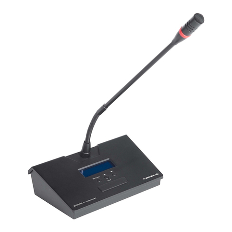
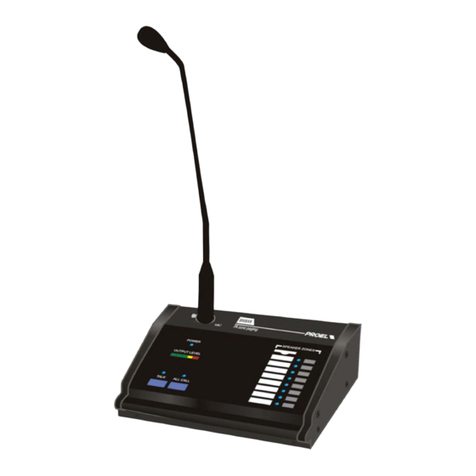
PROEL DBE108E User manual

DBE108E
Ethernet Desk Call Station
Postazione Microfonica da Tavolo Ethernet
USER’S MANUAL
MANUALE D’USO
ENGLISH
ITALIANO
96MAN0164-R EV.04/22

2
IMPORTANT SAFETY INSTRUCTIONS
Watch for these symbols:
The lightning flash with arrowhead symbol within an equilateral triangle is intended to alert the user to the
presence of uninsulated “dangerous voltage” within the product’s enclosure, which may be of sufficient magnitude
to constitute a risk of electric shock to persons.
The exclamation point within an equilateral triangle is intended to alert the user to the presence of important
operating and maintenance (servicing) instructions in the literature accompanying the appliance.
1. Read these instructions.
2. Keep these instructions.
3. Heed all warnings.
4. Follow all instructions.
5. Do not use this apparatus near water.
6. Clean only with dry cloth.
7. Do not block any ventilation openings. Install in accordance with the manufacturer’s instructions.
8. Do not install near any heat sources such as radiators, heat registers, stoves, or other apparatus (including
amplifiers) that produce heat.
9. Do not defeat the safety purpose of the polarized or grounding-type plug. A polarized plug has two blades with
one wider than the other. A grounding-type plug has two blades and a third grounding prong. The wide blade
or the third prong are provided for your safety. If the provided plug does not fit into your outlet, consult an
electrician for replacement of the obsolete outlet.
10. Protect the power cord from being walked on or pinched, particularly at plugs, convenience receptacles, and
the point where they exit from the apparatus.
11. Only use attachments/accessories specified by the manufacturer.
12.Use only with the cart, stand, tripod, bracket, or table specified by the manufacturer, or sold with the
apparatus. When a cart is used, use caution when moving the cart/apparatus combination to avoid injury
from tip-over.
13. Unplug this apparatus during lightning storms or when unused for long periods of time.
14. Refer all servicing to qualified service personnel. Servicing is required when the apparatus has been damaged
in any way, such as power supply cord or plug is damaged, liquid has been spilled or objects have fallen into the
apparatus, the apparatus has been exposed to rain or moisture, does not operate normally, or has been
dropped.
15. Warning: to reduce the risk of fire or electric shock, do not expose this apparatus to rain or moisture.
16. Do not expose this equipment to dripping or splashing and ensure that no objects filled with liquids, such as
vases, are placed on the equipment.
17. To completely disconnect this apparatus from the ac mains, disconnect the power supply cord plug from the ac
receptacle.
18. The mains plug of the power supply cord shall remain readily operable.
19. This apparatus contains potentially lethal voltages. To prevent electric shock or hazard, do not remove the
chassis, input module or ac input covers. No user serviceable parts inside. Refer servicing to qualified service
personnel.
20. This owner’s manual should be considered as a part of the product, it must always accompany it, and it needs
to be delivered to the new user when this product is sold. In this way the new owner will be aware of all the
installation, operating and safety instructions.
21. This apparatus should only be connected to a power source of type specified in this owner’s manual or on the
unit.
22. You can clean the exterior of the unit with compressed air or with a dry cloth.
23. Don’t clean the unit using solvents like trichloroethylene, thinners, alcohol, or other volatile or flammable
fluids.
24. To reduce the risk, close supervision is necessary when the product is used near children.
3
DISPOSAL OF OLD ELECTRICAL & ELECTRONIC EQUIPMENT
This marking shown on the product or its literature, indicates that it should not be disposed with other
household wastes at the end of its working life. To prevent possible harm to the environment or human health
from uncontrolled waste disposal, please separate this from other types of wastes and recycle it responsibly
to promote the sustainable reuse of material resources. Household users should contact either the retailer
where they purchased this product, or their local government office, for details of where and how they can take this
item for environmentally safe recycling. Business users should contact their supplier and check the terms and conditions
of the purchase contract. This product should not be mixed with other commercial wastes for disposal.
DECLARATION OF CONFORMITY
The product is in compliance with:
EN 54-16:2008 Voice Alarm Control and Indicating Equipment, RoHS Directive 2011/65/EU and
2015/863/EU, WEEE Directive 2012/19/EU.
CONDITIONS OF USE
Proel do not accept any liability for damage caused to third parties due to improper installation, use of non-original
spare parts, lack of maintenance, tampering or improper use of this product, including disregard of ascertainable and
applicable safety standards. Proel strongly recommends that this apparatus must be installed taking into consideration
all current National, Federal, State and Local regulations. The product must be installed by qualified personal. Please
contact the manufacturer for further information.
PACKAGING, SHIPPING AND COMPLAINT
This unit package has been submitted to ISTA 1A integrity tests. We suggest you control the unit conditions immediately
after unpacking it.
If any damage is found, immediately advise the dealer. Keep all unit packaging parts to allow inspection.
Proel is not responsible for any damage that occurs during shipment.
Products are sold “delivered ex warehouse” and shipment is at charge and risk of the buyer.
Possible damages to unit should be immediately notified to forwarder. Each complaint for manumitted package should
be done within eight days from product receipt.
WARRANTY AND PRODUCTS RETURN
Proel products have operating warranty and comply their specifications, as stated by manufacturer.
Proel warrants all materials, workmanship and proper operation of this product for a period of two years from the
original date of purchase. If any defects are found in the materials or workmanship or if the product fails to function
properly during the applicable warranty period, the owner should inform about these defects the dealer or the
distributor, providing receipt or invoice of date of purchase and defect detailed description. This warranty does not
extend to damage resulting from improper installation, misuse, neglect or abuse. Proel S.p.A. will verify damage on
returned units, and when the unit has been properly used and warranty is still valid, then the unit will be replaced or
repaired. Proel S.p.A. is not responsible for any "direct damage" or "indirect damage" caused by product defectiveness.

4
SUMMARY
IMPORTANT SAFETY INSTRUCTIONS............................................................................................................2
DISPOSAL OF OLD ELECTRICAL & ELECTRONIC EQUIPMENT .........................................................................3
DECLARATION OF CONFORMITY ..................................................................................................................3
CONDITIONS OF USE ...................................................................................................................................3
PACKAGING, SHIPPING AND COMPLAINT ....................................................................................................3
WARRANTY AND PRODUCTS RETURN..........................................................................................................3
INTRODUCTION...........................................................................................................................................5
DESCRIPTION ..............................................................................................................................................5
MAIN CONTROL PANEL................................................................................................................................5
REAR PANEL CONNECTIONS.........................................................................................................................6
DESCRIPTION OF THE WINDOWS DISPLAYED ON THE TOUCH SCREEN..........................................................7
1LIVE EVAC ........................................................................................................................................7
2EVAC MSg ........................................................................................................................................7
3ALERT MSg.......................................................................................................................................8
4PAGING ............................................................................................................................................8
5STATUS.............................................................................................................................................9
6CONFIG..........................................................................................................................................10
7INFO ..............................................................................................................................................10
CONFIGURATION OF INITIAL START-UP......................................................................................................11
MANUAL CONFIGURATION OF THE BUTTONS............................................................................................12
CONFIGURATION OF A GROUP ..................................................................................................................14
USE OF THE MICROPHONE STATION ..........................................................................................................15
USING THE TOUCH SCREEN TO MAKE CALLS OR SEND PRE-REGISTERED MESSAGES...................................16
1LIVE EVAC ......................................................................................................................................16
2EVAC MSg ......................................................................................................................................17
3ALERT MSg.....................................................................................................................................18
4PAGING ..........................................................................................................................................19
TECHNICAL SPECIFICATION ........................................................................................................................20

5
INTRODUCTION
Thank you for choosing a PROEL product. Please take the time to read this manual to understand all the
features of your system and make the most of its operational possibilities. All our products comply with CE
regulations for continuous use in sound diffusion systems.
DESCRIPTION
The DBE108E is an ETHERNET digital microphone station for use in Proel VAE voice alarm systems. This
completely digital device allows you to make emergency calls, paging calls, play alarm messages and view the
status of the control panels.
The connection is made via a UTP Cat. 5 cable in a computer network together with other DBE108E bases, in
addition to voice alarm systems.
MAIN CONTROL PANEL
To make the microphone station operational, the microphone must first be plugged into the socket on the
top panel (reference 1).
IMPORTANT
For connection and operation purposes, the DBE108E is a full-fledged ethernet network device and not an
audio equipment.
1. Socket for connecting the supplied Microphone.
2. Touch-Screen Display.
3. “LIVE EVAC” Emergency call button.
4. “EVAC MESSAGE” Evacuation message button.
5. “ALERT MESSAGE” Alarm message button.
6. “TALK” Call and Message activation button.
7. “PAGING” Service Call / Paging touch button.
8. “X” Cancel / Undo touch button.

6
9. “UP” e “DOWN” Scrolling Up and Down touch buttons.
10. “1”…”8” Group selection touch buttons.
REAR PANEL CONNECTIONS
On the rear panel there is the power jack connector and the 10/100 Ethernet port.
1. Power supply connector 18 ÷ 24Vdc (+ internal, - external) - 0.6 A.
ATTENTION: use only the supplied power supply unit.
2. RJ45 connector (Ethernet port).
The figure shows the standard pinout of the RJ45 plug:

7
DESCRIPTION OF THE WINDOWS DISPLAYED ON THE TOUCH SCREEN
By starting the microphone station in configuration mode (see next chapter) and pressing the "Labels" at the
top of touchscreen, you will be able to access the 7 windows corresponding to specific functions. If instead
you access the microphone station in standard user mode, some windows will not be available.
1LIVE EVAC
From this window it is possible to make emergency voice calls on the various Evac units.
Note: refer to the USING THE MICROPHONE STATION chapter and following.
2EVAC MSg
From this window it is possible to send each of the connected Evac units its own Evacuation Message.
Note: refer to the USE OF THE MICROPHONE STATION chapter and following.

8
3ALERT MSg
From this window it is possible to send each of the connected Evac units its own Alert Message.
Note: refer to the USING THE MICROPHONE STATION chapter and following.
4PAGING
From this window it is possible to make paging calls on the single zones or groups of the different Evac
units.
Note: refer to the USING THE MICROPHONE STATION chapter and following.

9
5STATUS
This window shows the information on the status of the Evac units in the network.
EVAC CODE column: shows the unique identification number of the CPU of the EVAC unit.
EVAC TYPE column: shows the type of EVAC unit.
EVAC NAME column: shows the name of the EVAC unit, assigned by the ETHERNET configuration menu
of the unit itself.
Hint
For a simpler interpretation of the system on the network, it is advisable to sequentially name the control
units that make up the system.
STATUS column: shows the of the EVAC unit:
CONNECTED – Unit connected.
COMM ERROR – Unit disconnected (check the cable and/or disable and enable again the “Fire
Microphone” function on the Evac unit). When this error is displayed, all the buttons of the
unit will be WHITE.
NOT AVAILABLE – Occurs when the Ethernet Switch is restarted and a previously configured Evac
unit is not detected. When this error is displayed, all the buttons of the unit will be WHITE.
FAULT – The Evac unit has an anomaly, check its display. When this error is displayed, all the
buttons of the unit will be ORANGE.
IMPORTANT
Once the DBE108E is inserted into a network together with the EVAC devices and after self-configuration,
the DBE108E will start monitoring them.
In case of lack of connection between the control panels and the DBE108E, a Fault Warning will be
generated. In particular, we can distinguish two cases:
•Loss of connection of one or more EVAC systems: all systems that have lost the connection go
into the Fault-Warning state, on the DBE108E the relative buttons will turn WHITE and in the
"STATUS" window corresponding to those control units the message "COMM ERROR" will be
shown.
•DBE108E connection loss: all systems go into Fault-Warning status, on the DBE108E all zone
buttons will turn WHITE and the “COMM ERROR” message will be shown on all units in the
“STATUS” window.

10
NOTE
The following buttons are displayed only in Configuration mode:
CLEAR GROUP button: allows you to clear all created groups at the same time. To create a group, refer
to the dedicated chapter.
AUTO BUTTON: allows you to assign call buttons to each Evac unit. To configure the base, refer to the
dedicated chapter.
RESET DATA button:it deletes all the programming of the base, restoring it to the factory values.
6CONFIG
In this window it is possible to manually set the individual buttons relating to the connected units.
NOTE
This page is displayed only in configuration mode.
Note: for the use of this function, refer to the CONFIGURATION OF INITIAL START-UP chapter.
7INFO
The assignments made during the programming of the various buttons and groups of the DBE108E are
here summarized.
NOTE
This page is displayed only in configuration mode.
EVAC Column: shows the name of the EVAC unit.

11
BTN Column: shows the button relating to the EVAC unit.
EN Column: if the symbol "*" is present, the corresponding button is enabled and will be visible on the
display.
LABEL Column: name assigned to the button.
LINEOUT Column: speaker line (A + B) of the corresponding EVAC unit associated with the button.
GRP Column: if present, it shows the number of the group to which the button is associated.
CONFIGURATION OF INITIAL START-UP
The DBE108E must be plugged into a network where an Ethernet Switch with DHCP Server function is
present and active. The DBE108E is designed to work with both AE300 and / or AE604 for a total of 8 Evac
units.
To facilitate the identification, before networking the EVAC units, it is advisable to assign a unique name to
each of them from the unit’s Ethernet menu. In this guide, the following names have been assigned for the
three Evac units used as an example: AE604-1, AE300-1 and AE604-2.
For the first configuration proceed as follows:
•Make sure you have turned off all Evac units, bases and switches connected to the network.
•Turn on the DHCP Switch Server and any other switches on the network.
•Connect the AE300 / AE604 Evac units to the ethernet network.
•Switch on the AE300 / AE604 Evac units.
•Finally connect the DBE108E bases leaving the power supply disconnected.
•Turn on each DBE108E base by connecting the power cable while time holding down the “EVAC
MESSAGE” button: the bases start in configuration mode and automatically acquire the Evac units
connected to the network.
If you want to give a particular order of the Evac units that appear in the “STATUS” window (see point 5 of
the previous chapter), you must have the Evac units acquired one at a time in the desired sequence.
To do that, first turn on all the DBE108E present in the network in configuration mode (supplying the external
power supply while holding down the "EVAC MESSAGE" button) and then the Evac units in the desired order.
Wait for the single Evac unit to be displayed in the “STATUS” window before turning on the next one.
In the example shown in the figure, 3 Evac units have been connected in sequence: Evac unit n ° 1 AE604-1,
Evac unit n ° 2 AE300-1, Evac unit n ° 3 AE604-2.

12
•From the “STATUS” window, press “AUTO BUTTON”.
With this operation, the base is automatically programmed in a standard way, associating an EVAC unit to
each row of the display following the acquisition order of the various units. 4 buttons are displayed in each
row if the Evac is an AE604, while only one button is displayed if the Evac is an AE300.
The name of the EVAC AE604 / AE300 is shown inside each display button, followed by the number of the
assigned output line and with the name of the zone underneath. Repeat the “AUTO BUTTON” procedure on
other DBE108Es if present.
In the example, 4 buttons are assigned to the AE604-1 for zones 1..4, 1 button for the AE300-1 and 4 other
buttons to the AE604-2.
NOTE
Once the DBE108E bases have been programmed, by disconnecting or reconnecting the bases or the
various Evac units, the acquisition order of the Evac units remains unchanged.
MANUAL CONFIGURATION OF THE BUTTONS
Pressing the "CONFIG" label will open the corresponding page.
By pressing the triangle on the first drop-down menu at the top left, it is possible to select the EVAC unit
whose buttons you want to configure.

13
The name of the EVAC system is that one set on the Evac unit from the “Ethernet menu”: for details, see the
Evac unit manual.
Once the control unit has been selected, open the flag menu that identifies the buttons associated with the
Evac unit. In this example, since the unit is an AE604, 4 buttons will be editable: “BUTTON1”, “BUTTON2”,
“BUTTON3” and “BUTTON4”. If the selected control unit is an AE300, only “BUTTON1” is editable.
Once the button to be programmed has been selected, you can enable it by clicking on the “ENABLE”. If you
decide not to enable it, the button will not be displayed on the call windows, leaving an empty position.
In the automatic self-configuration procedure ("AUTO BUTTON" function), the "BUTTON1" is assigned the
speaker output (A + B) n ° 1 LINEOUT1 (ALL LINES in case of AE300), the name ZONE1 (ZONE in case of
AE300) and ENABLE active, thus to the following buttons:
“BUTTON2” respectively “LINEOUT2”, “ZONE2”, “ENABLED”
“BUTTON3” respectively “LINEOUT3”, “ZONE3”, “ENABLED”
“BUTTON4” respectively “LINEOUT4”, “ZONE4”, “ENABLED”
In this window it is also possible to change the name previously assigned by the autoconfiguration
procedure: by pressing on the name (in this case ZONE1), the cursor starts flashing and the new name can be
entered using the alphanumeric keypad (maximum 8 characters).
In the case of AE604, through the “LINEOUT” pull-down menu it is possible to assign any of the speaker
outputs (A + B) of the Evac unit or all of them (ALL LINES) to the selected button. To do this, open the drop-
down menu of physical outputs and select the desired output or assign them all using the ALL LINES setting.

14
To make the settings effective, before selecting another Evac unit or configuring another button from the
drop-down menu, press the "STORE" button.
CONFIGURATION OF A GROUP
The microphone console has 8 call GROUPS which can be called up directly from the buttons on the panel.
By pressing the GROUP "n" button, all the zone buttons previously associated with that group will be
automatically selected: at this point you can proceed with the desired call or message operation.
To associate a zone button to a group, after selecting the "BUTTON", proceed by selecting the desired group
from the "GROUP" menu.
After assigning the button to the group, press the "STORE" button to store the setting.
If it is necessary to cancel only the programming of the Groups without reprogramming the entire base, use
the "CLEAR GROUP" button in the "STATUS" window.
IMPORTANT: the “CLEAR GROUP” function deletes all groups!

15
USE OF THE MICROPHONE STATION
Once the configuration is complete, the base must be turned off and on again using the power connector
without pressing any button. In this way, the base will work in standard mode for the end user.
To facilitate the user, the DBE108E allows you to make an emergency call, paging or play messages on all
zones without operating on the touch-screen display:
EMERGENCY CALL
+
Press the LIVE EVAC button and then the TALK button.
In this way the microphone is “opened” on all the
zones of all the Evac units in the network.
EVACUATION MESSAGE
+
Press the EVAC MESSAGE button and then the TALK
button. The evacuation message is reproduced on all
zones of all Evac units in the network.
Note: the message reproduced is the one present inside
each Evac unit in the network.
ALERT MESSAGE
+
Press the ALERT MESSAGE button and then the TALK
button. The alert message is reproduced on all zones of
all Evac units in the network.
Note: the message reproduced is the one present inside
each Evac unit in the network.
PAGING CALL
+
Press the PAGING key and then the TALK key. In this
way the microphone is “opened” on all the zones of all
the Evac units in the network.
GROUP CALL
+
Press the button of the group of zones on which you
want to make the call and then the TALK key. In this
way the microphone is “opened” on all the zones of the
group programmed as per the previous chapter.
Note: this is valid only with PAGING window selected on
display, in case the selected page is LIVE EVAC, EVAC
MSg, ALERT MSg the respective microphone or
message is sent to all zones of the Evac unit which has
at least one zone in the group.
CALL CANCELLATION
"CANCEL" button for canceling the zones selected for
the call. After 30 seconds the zones will be deselected
anyway.

16
USING THE TOUCH SCREEN TO MAKE CALLS OR SEND PRE-REGISTERED
MESSAGES
1LIVE EVAC
Evacuation announcement from DBE108E microphone station.
Pressing the "LIVE EVAC" label will open the corresponding page and all the enabled buttons of the
connected Evac units will be displayed. In the current example three Evac units are displayed, but if you
connect more Evac units to view all the zone keys it will be necessary to scroll the window using the vertical
touch bar or using the two capacitive keys "UP" and "DOWN".
Note: in the LIVE EVAC function, the announcement is sent to the entire Evac control unit and not to the
single zone. Therefore, referring to the figure above, by clicking one of the 4 keys relating to the AE604-1, all 4
buttons will be automatically selected and will take on a lighter color tone.
After you have selected all the Evac units you want to send the message to (the buttons of which will take on
a lighter tone), by keeping the "TALK" button pressed, the announcement from the microphone will be
reproduced, during which the buttons of the Evac units involved will become red.
When the “TALK” button is released, the Evac units will remain selected for about 30 seconds: anyway, they
can be deselected in any moment by pressing the zone buttons again or the “CANCEL” button.
Note: in the case of several DBE108E bases connected to the network, if a base is sending a message in "LIVE
EVAC" on one or more Evac units, the zone buttons of the Evac units involved in the other bases connected
(always at the "LIVE EVAC" level) will be gray, to indicate that they are in use, and it will not be possible to
make the announcement on those units until the other operator has finished.

17
2EVAC MSg
Playback of the evacuation message recorded on the Evac unit.
By pressing on the "EVAC MSg" label, the corresponding page will open and all the enabled buttons of the
connected Evac units will be displayed. In the current example three Evac units are displayed, but if more
than 4 Evac units are connected, to display all the zone buttons it will be necessary to scroll the window using
the vertical touch bar or simply using the two capacitive keys "UP" and "DOWN".
Note: in the EVAC Msg function, the Evac message is sent to the entire Evac unit and not to the single zone.
Therefore, referring to the figure above, by clicking one of the 4 buttons relating to the AE604-1, all 4 buttons
will be automatically selected and will take on a lighter color tone.
After you have selected all the Evac units you want to send the message to (the buttons of which will take on
a lighter tone), by pressing the “TALK” button the pre-recorded Evac message will be reproduced cyclically.
During playback, the buttons of the Evac units involved will turn red: by pressing the ”TALK” button again,
the playback will be stopped.
When the “TALK” button is released, the Evac units will remain selected for about 30 seconds: anyway, they
can be deselected in any moment by pressing the zone buttons again or the “CANCEL” button.
Note: in the case of several DBE108E bases connected to the network, if a base is reproducing a message in
"EVAC MSg" on one or more Evac units, in the other connected bases (always at the "EVAC MSg" level) the
zone buttons of the Evac units involved will be gray color, to indicate that they are in use, and it will not be
possible to make the announcement on these Evac units until the other operator has finished.
However, if another base is used in "LIVE EVAC", it will have priority, thus going to by-pass the base in use in
"EVAC MSg" mode.

18
3ALERT MSg
Playback of the alert message recorded on the Evac unit.
Pressing the "ALERT Msg" label will open the corresponding page and all the enabled buttons of the
connected Evac units will be displayed. If more than 4 Evac units are connected, to view all the zone buttons
it will be necessary to scroll the window using the vertical touch bar or simply using the two capacitive keys
“UP” and “DOWN”.
Note: in the ALERT Msg function, the Alert message is sent to the entire Evac unit and not to the single zone.
Therefore, referring to the figure above, by clicking one of the 4 buttons relating to the AE604-1, all 4 buttons
will be automatically selected and will take on a lighter color tone.
After you have selected all the Evac units you want to send the message to (the buttons of which will take on
a lighter tone), by pressing the “ TALK” button the pre-recorded Alert message will be reproduced cyclically.
During playback, the buttons of the Evac units involved will turn red, by pressing the "TALK" button again,
playback will be stopped.
When the “TALK” button is released, the Evac units will remain selected for about 30 seconds: anyway, they
can be deselected in any moment by pressing the zone buttons again or the “CANCEL” button.
Note: in the case of several DBE108E bases connected to the network, if a base is reproducing a message in
"ALERT Msg" on one or more Evac units, in the other connected Bases (always at the "ALERT Msg" level) the
zone buttons of the Evac units involved will be gray color, to indicate that they are in use, and it will not be
possible to make the announcement on these Evac units until the other operator has finished.
However, if another base is used in "LIVE EVAC" or "EVAC MSg" it will have priority, thus going to by-pass the
base in use in "ALERT MSg" mode.

19
4PAGING
Generic announcement from DBE108E microphone station.
By pressing on the "PAGING" label, the corresponding page will open and all the enabled buttons of the
connected Evac units will be displayed. If more than 4 Evac units are connected, to view all the zone keys, it
will be necessary to scroll the window using the vertical Touch bar or simply using the two capacitive keys
“UP” and “DOWN”.
Note: in the PAGING function, the announcement can be sent to a single zone or to groups of zones. By
clicking on the zone buttons of one or more Evac units they will take on a lighter color tone and by keeping the
"TALK" button pressed, the announcement will be reproduced from microphone.
When the “TALK” button is released, the Evac units will remain selected for about 30 seconds: anyway, they
can be deselected in any moment by pressing the zone buttons again or the “CANCEL” button.
Note: in the case of several DBE108E bases connected in the network, if a base is sending a Paging message
on one zone or more zones, in the other connected Bases (always at Paging level) the zone buttons of the
entire control units involved will be gray, to indicate that are in use, and it will not be possible to announce on
these exchanges until the other operator has finished.
However, if another base is used in "LIVE EVAC", "EVAC Msg" or "ALERT Msg" it will have priority, thus going
to by-pass the base in use in "PAGING" mode.

20
TECHNICAL SPECIFICATION
Model:
DBE108E
Sensitivity:
-55dB ± 3dB
Frequency Response:
400Hz ÷ 8KHz (-3dB)
Dynamic range:
72dB
Gooseneck type:
Dynamic
Gooseneck length:
390 mm
I/O Connector:
1x Ethernet 10/100
Power supply:
18÷24Vdc – 0.6A
Dimensions (W x H x D):
165 x 178 x 442 mm
Weight:
0.8 Kg
Other manuals for DBE108E
1
Table of contents
Languages:
Other PROEL Microphone System manuals

PROEL
PROEL RMW10 User manual

PROEL
PROEL RMW821 User manual

PROEL
PROEL WM202 User manual

PROEL
PROEL RM100 User manual

PROEL
PROEL BM8X8 User manual

PROEL
PROEL BPLL User manual

PROEL
PROEL RMW8 Series User manual

PROEL
PROEL PA BMT MIC BASE User manual

PROEL
PROEL RMW1000 Series User manual

PROEL
PROEL RMW1000 Series User manual

PROEL
PROEL RMW1000 Series User manual

PROEL
PROEL WM240 User manual

PROEL
PROEL WM600 User manual

PROEL
PROEL RMW1000M User manual

PROEL
PROEL WM600DH User manual

PROEL
PROEL RM100 User manual

PROEL
PROEL RMW10 User manual

PROEL
PROEL WM101 Series User manual

PROEL
PROEL RM200 User manual

PROEL
PROEL WM202D User manual