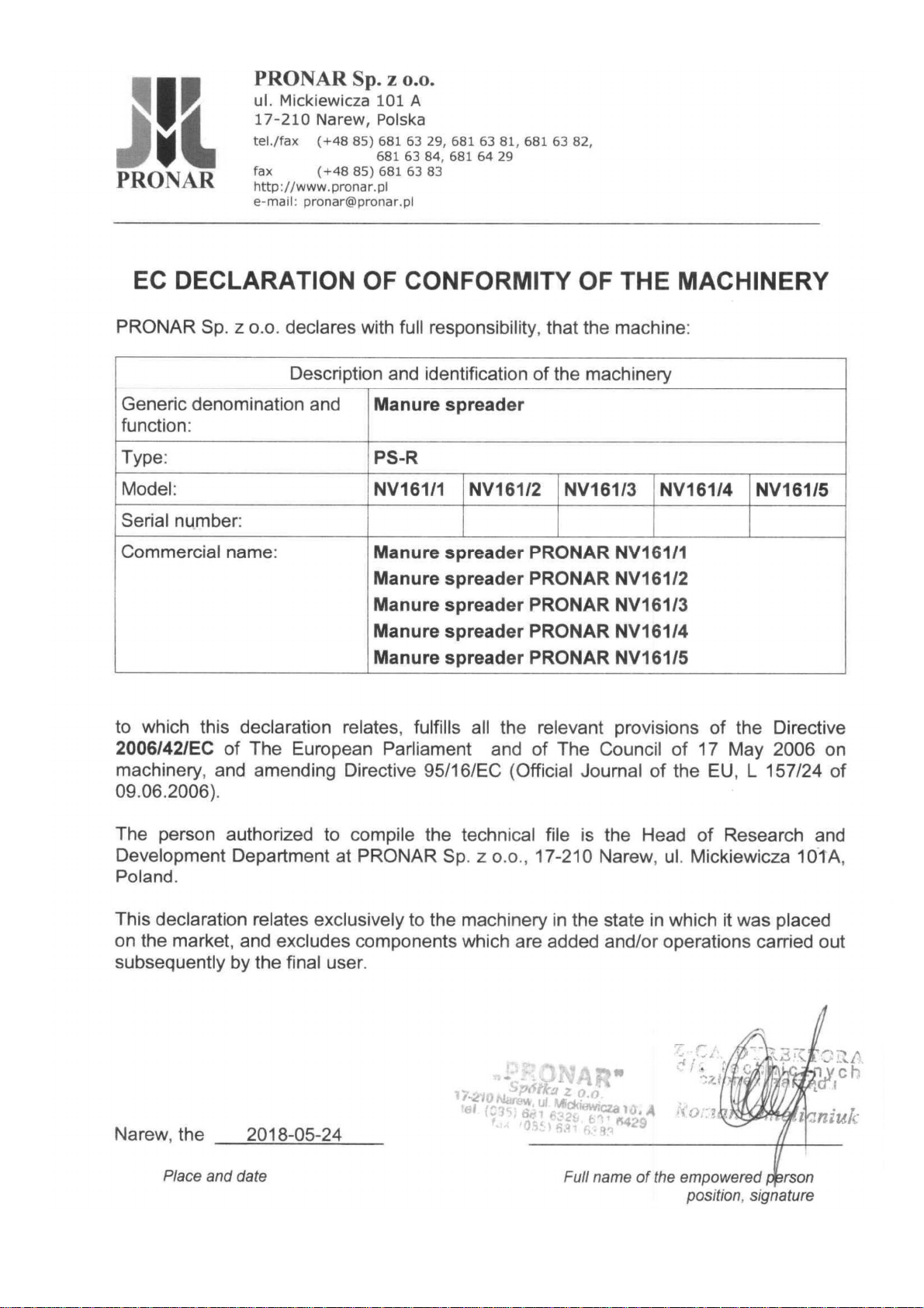
PRONAR NV161/1 User manual

PRONAR Sp. z o.o.
17-210 NAREW, UL. MICKIEWICZA 101A, PODLASKIE PROVINCE
phone: +48 085 681 63 29 +48 085 681 64 29
+48 085 681 63 81 +48 085 681 63 82
fax: +48 085 681 63 83 +48 085 682 71 10
www.pronar.pl
OPERATOR'S MANUAL
MANURE SPREADER
PRONAR NV161/1, PRONAR NV161/2
PRONAR NV161/3, PRONAR NV161/4
PRONAR NV161/5
TRANSLATION OF THE ORIGINAL COPY OF THE MANUAL
EDITION 2C-10-2020 PUBLICATION NO. 523N-00000000-UM


INTRODUCTION
Information contained herein is current at date of publication. As a result of improvements,
some numerical values and illustrations contained in this publication may not correspond to the
factual specification of the machine supplied to the user. The manufacturer reserves the right to
introduce design changes in machines produced that facilitate operation and improve the quality
of their work, without making minor amendments to this Operator's Manual.
This Operator's Manual is an integral part of the machine's documentation. Before using the
machine, the user must carefully read this Operator's Manual and observe all
recommendations. This guarantees safe operation and ensures failure-free work of the
machine. The machine is designed to meet obligatory standards, documents and legal
regulations currently in force.
The Operator's Manual describes the basic safety rules and operation of Pronar NV161/1,
NV161/2, NV161/3, NV161/4 and NV161/5 manure spreader.
If the information stated in the Operator's Manual needs clarification then the user should refer
for assistance to the sale point where the machine was purchased or to the Manufacturer.
MANUFACTURER'S ADDRESS:
PRONAR Sp. z o.o.
ul. Mickiewicza 101A
17-210 Narew
CONTACT TELEPHONES
+48 085 681 63 29 +48 085 681 64 29
+48 085 681 63 81 +48 085 681 63 82

SYMBOLS APPEARING IN THIS OPERATOR'S MANUAL
Information, descriptions of danger and precautions and also recommendations and prohibitions
associated with user safety instructions are marked:
and also preceded by the word "DANGER”. Failure to observe the instructions may endanger
the machine operator's or other person's health or life.
Particularly important information and instructions, the observance of which is essential, are
distinguished in the text by the sign:
and also preceded by the word "ATTENTION". Failure to observe the instructions may lead to
damage to the machine as a result of improper operation, adjustment or use.
In order to focus the user's attention on the need to perform maintenance, the relevant section
of the Operator's Manual is marked with the pictogram:
Additional tips and advice for machine operation are marked:
and also preceded by the word "TIP".

DIRECTIONS USED IN THIS OPERATOR'S MANUAL
Left side – side to the left hand of the operator facing in the direction of machine's forward
travel.
Right side – side to the right hand of the operator facing in the direction of machine's forward
travel.
REQUIRED MAINTENANCE ACTIONS
Maintenance actions described in the manual are marked with the sign:
Result of maintenance/adjustment actions or comments concerning the performance of actions
are marked with the sign:


CONTENTS
1
BASIC INFORMATION 1.1
1.1
IDENTIFICATION 1.2
1.1.1 AXLE IDENTIFICATION 1.4
1.1.2 LIST OF FACTORY NUMBERS 1.5
1.2
INTENDED USE 1.5
1.3
EQUIPMENT 1.8
1.4
TERMS & CONDITIONS OF WARRANTY 1.9
1.5
TRANSPORT 1.11
1.5.1 TRANSPORT ON VEHICLE 1.11
1.5.2 INDEPENDENT TRANSPORT BY THE USER 1.12
1.6
ENVIRONMENTAL HAZARDS 1.13
1.7
WITHDRAWAL FROM USE 1.14
2
SAFETY ADVICE 2.1
2.1
BASIC SAFETY RULES 2.2
2.1.1 USE OF MANURE SPREADER 2.2
2.1.2 HITCHING AND UNHITCHING THE MANURE SPREADER,
LOADING THE LOAD BOX 2.3
2.1.3 TRANSPORTING THE MACHINE 2.4
2.1.4 HYDRAULIC SYSTEM AND PNEUMATIC SYSTEM 2.6
2.1.5 OPERATION WITH PTO 2.7
2.1.6 MACHINE OPERATION 2.9
2.1.7 CLEANING, MAINTENANCE AND REPAIRS 2.9
2.2
DESCRIPTION OF RESIDUAL RISK 2.11
2.3
INFORMATION AND WARNING DECALS 2.12

3
DESIGN AND OPERATION 3.1
3.1
TECHNICAL SPECIFICATION 3.2
3.2
MANURE SPREADER DESIGN 3.4
3.2.1 GENERAL DESIGN 3.4
3.2.2 FEEDING MECHANISM 3.5
3.2.3 HYDRAULIC SYSTEM OF FEEDING MECHANISM 3.8
3.2.4 DRIVE TRANSMISSION 3.9
3.2.5 TWO-BEATER VERTICAL SPREADER UNIT 3.11
3.2.6 TAILGATE OPENING HYDRAULIC SYSTEM 3.12
3.2.7 HYDRAULIC SYSTEM OF THE SLIDE GATE 3.13
3.2.8 MAIN BRAKE 3.14
3.2.9 PARKING BRAKE 3.19
3.2.10 LIGHTING SYSTEM 3.20
4
CORRECT USE 4.1
4.1
PREPARING FOR WORK BEFORE FIRST USE 4.2
4.1.1 CHECKING THE MANURE SPREADER AFTER DELIVERY 4.2
4.1.2 PREPARING THE MANURE SPREADER FOR THE FIRST USE 4.3
4.1.3 TEST START 4.4
4.2
TECHNICAL CONDITION INSPECTION 4.6
4.3
HITCHING AND DISCONNECTING MANURE SPREADER
FROM TRACTOR 4.7
4.4
LOADING THE LOAD BOX 4.12
4.5
SPREADING AND ADJUSTING FERTILIZER DOSE 4.13
4.5.1 ADJUSTING FERTILIZER DOSE 4.13
4.5.2 SPREADING MANURE IN THE FIELD 4.14
4.6
SPREADING MECHANISM CLOGGING 4.16
4.7
PROPER USE AND MAINTENANCE OF TYRES 4.17

5
MAINTENANCE 5.1
5.1
PRELIMINARY INFORMATION 5.2
5.2
MAINTENANCE OF BRAKES AND AXLES 5.2
5.2.1 PRELIMINARY INFORMATION 5.2
5.2.2 INITIAL INSPECTION OF AXLE BRAKES 5.3
5.2.3 CHECKING BRAKE SHOE LININGS FOR WEAR 5.4
5.2.4 CHECKING WHEEL AXLE BEARINGS FOR SLACKNESS 5.5
5.2.5 ADJUSTMENT OF SLACKNESS OF WHEEL AXLE BEARINGS 5.7
5.2.6 MOUNTING AND DISMOUNTING WHEEL, INSPECTION OF
WHEEL NUT TIGHTENING 5.8
5.2.7 CHECKING AIR PRESSURE IN TYRES, EVALUATING
TECHNICAL CONDITION OF TYRES AND STEEL WHEELS 5.10
5.2.8 MECHANICAL BRAKES ADJUSTMENT 5.11
5.2.9 CHANGE OF PARKING BRAKE CABLE AND ADJUSTMENT OF
CABLE TENSION. 5.15
5.3
PNEUMATIC SYSTEM MAINTENANCE 5.18
5.3.1 PRELIMINARY INFORMATION 5.18
5.3.2 CHECKING AIR TIGHTNESS AND VISUAL INSPECTION OF
PNEUMATIC SYSTEM 5.19
5.3.3 CLEANING THE AIR FILTERS 5.20
5.3.4 DRAINING WATER FROM AIR TANK 5.22
5.3.5 CLEANING THE DRAIN VALVE 5.23
5.3.6 CLEANING AND MAINTAINING PNEUMATIC CONDUIT
CONNECTIONS AND PNEUMATIC SOCKETS 5.23
5.3.7 REPLACEMENT OF PNEUMATIC CONDUIT 5.24
5.4
HYDRAULIC SYSTEM OPERATION 5.25
5.5
MAINTENANCE OF MANURE SPREADER GEARS 5.27
5.6
MANURE SPREADER LUBRICATION 5.30
5.7
CHECKING AND ADJUSTMENT OF TENSION OF FLOOR
CONVEYOR CHAINS 5.36

5.8
MANURE SPREADER CLEANING 5.37
5.9
PREPARATION FOR END OF SEASON 5.39
5.10
PREPARATION FOR THE BEGINNING OF A NEW
FIELDWORK SEASON 5.40
5.11
STORAGE 5.41
5.12
MAINTENANCE OF ELECTRICAL SYSTEM AND WARNING
ELEMENTS 5.42
5.12.1 PRELIMINARY INFORMATION 5.42
5.12.2 CHANGING BULBS 5.43
5.13
TIGHTENING TORQUE FOR NUT AND BOLT
CONNECTIONS 5.43
5.14
TROUBLESHOOTING 5.45

SECTION
1
BASIC
INFORMATION

Pronar NV161/1 │ NV161/2 │ NV161/3│ NV161/4 │ NV161/5 SECTION 1
1.2
1.1 IDENTIFICATION
FIGURE 1.1 Manure spreader identification
(1) data plate – version standard, (2) data plate – version EU, (3) data plate CE– version EU,
(4) serial number
The manure spreader is marked with the data plate (1) – version standard, or (2) and (3) -
version EU and the factory number (4) located on a gold painted rectangle. The serial
number and data plate are located on the front wall of the load box - figure (1.1).

SECTION 1 Pronar NV161/1 │ NV161/2 │ NV161/3│ NV161/4 │ NV161/5
1.3
When buying the manure spreader check that the factory numbers on the machine agree
with the number written in the WARRANTY BOOK, in the sales documents and in the
OPERATOR'S MANUAL.The meanings of the individual fields found on the data plate are
presented in the table (1.1), (1.2), (1.3).
TABLE 1.1 Markings on data plate- version standard
ITEM
MARKING
A General description and purpose
B Symbol /Type
C Year of manufacture
D Seventeen digit serial number (VIN)
E Official certificate number
F Machine tare weight
G Maximum gross weight
H Carrying capacity
I Permissible hitching system loading
J Permissible front axle load
K Permissible rear axle load
TABLE 1.2 Markings on data plate- version EU
ITEM
MARKING
A Vehicle category according to R167/2013
B Official certificate number
C Seventeen digit serial number (VIN)
D Maximum gross weight
E Permissible hitching system loading
F Permissible load – axle 1
G Permissible load – axle 2
H Permissible load – axle 3
I Technically permissible towable mass for each chassis/braking configuration for R or
S category Vehicle

Pronar NV161/1 │ NV161/2 │ NV161/3│ NV161/4 │ NV161/5 SECTION 1
1.4
TABLE 1.3 Markings on data plate CE - version EU
ITEM
MARKING
A General description and purpose
B Seventeen digit serial number (VIN)
C Type
D Year of manufacture
E Model
1.1.1 AXLE IDENTIFICATION
The factory number of the axle shaft and its type are stamped onto the data plate (2) secured
to the axle shaft beam (1) – figure (1.2).
FIGURE 1.2 Location of the axle data plate
(1) axle, (2) data plate

SECTION 1 Pronar NV161/1 │ NV161/2 │ NV161/3│ NV161/4 │ NV161/5
1.5
1.1.2 LIST OF FACTORY NUMBERS
TIP
In the event of ordering a replacement part or if problems appear it is often essential to
give the factory n mbers of parts or the VIN n mber of the man re spreader, therefore it
is recommended that these n mbers are inscribed in the spaces below.
VIN
S Z B 1 6 1 X X X
AXLE FACTORY NUMBER AND TYPE
1.2 INTENDED USE
Pronar single axle manure spreader is designed for uniform spreading of all kinds of manure,
peat and compost. The manure spreader must not be used in any way other than that
described above. Using it as intended also involves all actions connected with the safe and
proper operation and maintenance. The manure spreader is not intended or designed for
transporting people or animals.
ATTENTION!
The man re spreader m st not be sed for p rposes other than those for which it is
intended, in partic lar:
•for transporting people and animals,
•
for applications in which the maximum carrying capacity is
exceeded,
•for spreading and transporting toxic and flammable materials,
•for spreading fluids, sand or fibrous substances,
•for transporting unsecured loads, which may move
in the load box
during transport,

Pronar NV161/1 │ NV161/2 │ NV161/3│ NV161/4 │ NV161/5 SECTION 1
1.6
•
for transporting machines and equipment with high centre of
gravity deteriorating manure spreader stability,
•
for transporting construction materials, single objects or any
materials and substances outside the scope of inte
nded use of the
manure spreader.
The manure spreader is constructed according to current safety requirements and
engineering standards. The brake system and the light and indicator system meet the
requirements of road traffic regulations. The maximum speed of the manure spreader on
public roads is 30 km/h in Poland (pursuant to Traffic Law Act of June 20th 1997, article 20).
In the countries where the manure spreader is used, the limits stipulated by the road traffic
legislation in force in a given country must be observed. The manure spreader speed must
not, however, be greater than the maximum design speed.
Using it as intended also involves all actions connected with the safe and proper operation
and maintenance of the machine. In connection with this the user is obliged to:
•carefully read the OPERATOR'S MANUAL of the manure spreader and the
WARRANTY BOOK and conform with the recommendations contained in these
documents,
•understand the manure spreader's operating principle and how to operate it safely
and correctly,
•adhere to the established maintenance and adjustment plans,
•comply with general safety regulations while working,
•prevent accidents,
•comply with the road traffic regulations and transport regulations in force in a
given country, in which the manure spreader is used,
•carefully read the Operator's Manual and comply with its recommendations,
•only hitch the manure spreader to an agricultural tractor which fulfils all the
requirements made by the Manufacturer of the manure spreader.
The manure spreader may only be used by persons, who:

SECTION 1 Pronar NV161/1 │ NV161/2 │ NV161/3│ NV161/4 │ NV161/5
1.7
•are familiar with the contents of this publication and with the contents of the
Operator's Manual of the agricultural tractor,
•have been trained in manure spreader operation and work safety,
•have the required authorisation to drive and are familiar with the road traffic
regulations and transport regulations.
TABLE 1.4 Agricultural tractor's requirements
CONTENTS UNIT REQUIREMENTS
Braking system - sockets
Single conduit pneumatic system
Double conduit pneumatic system
Hydraulic system
Pressure rating of the system
Single conduit pneumatic system
Double conduit pneumatic system
Hydraulic system
-
-
-
bar
bar
bar / MPa
according to A DIN 74 294
according to ISO 1728
according to ISO 7421-1
5.8 - 6.5
6.5
150 / 15
Hydraulic system
Number of connections
Hydraulic oil
Pressure rating of the system
-
-
bar / MPa
2 (standard) + 4 (options)
L-HL32 Lotos
(1)
160 / 16
Electrical system
Electrical system voltage
Connection socket
V
-
12
7-pole compliant with ISO 1724

Pronar NV161/1 │ NV161/2 │ NV161/3│ NV161/4 │ NV161/5 SECTION 1
1.8
CONTENTS UNIT REQUIREMENTS
Other requirements
PTO RPM
NV161/1, NV161/2
NV161/3, NV161/4, NV161/5
The required minimum power
NV161/1
NV161/2
NV161/3
NV161/4
NV161/5
Minimum static vertical load capacity (S)
NV161/1
NV161/2
NV161/3
NV161/4
NV161/5
RPM
RPM
hp / /kW
hp / /kW
hp / /kW
hp / /kW
hp / /kW
kg
kg
kg
kg
kg
540
1,000
70 / 51.5
80 / 58.8
90 / 66.2
100 / 73.5
120 / 88.2
2,000
2,500
3,000
3,000
4,000
(1)
– use of other oil is permitted on condition that it may be mixed with the oil in the manure spreader.
Detailed information may be found on the product information card.
1.3 EQUIPMENT
When buying the manure spreader check completeness of the machine.
TABLE 1.5 Manure spreader equipment
EQUIPMENT
STANDARD
ADDITIONAL
OPTIONS
Operator's Manual •
Warranty book •
This manual suits for next models
4
Other PRONAR Farm Equipment manuals

PRONAR
PRONAR T669/1 User manual

PRONAR
PRONAR T286 User manual

PRONAR
PRONAR T679/5 User manual

PRONAR
PRONAR T740 User manual

PRONAR
PRONAR ZKP460T User manual

PRONAR
PRONAR T679/3 User manual

PRONAR
PRONAR PWP900 User manual

PRONAR
PRONAR T669 User manual

PRONAR
PRONAR T185/1 User manual

PRONAR
PRONAR PWP460 User manual

PRONAR
PRONAR ZKP801 User manual

PRONAR
PRONAR TG110 User manual

PRONAR
PRONAR PDF301 User manual

PRONAR
PRONAR VMP-5ST User manual

PRONAR
PRONAR ZKP350 User manual

PRONAR
PRONAR T679/4M User manual

PRONAR
PRONAR T386 User manual

PRONAR
PRONAR PT512 User manual

PRONAR
PRONAR ZKP690 User manual

PRONAR
PRONAR ZKP800 User manual