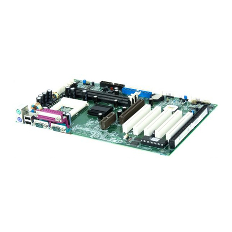
QDI KinetiZ 7T User manual

Declaration of conformity
QUANTUMDESIGNS(HK)LTD.
5/F Somerset House, TaiKoo Place 979 Kings Road,
Quarry Bay, Hong Kong
declares that the product
Mainboard
KinetiZ 7T
is in conformity with
(reference to the specification under which conformity is declared in
accordance with 89/336 EEC-EMC Directive)
þ EN 55022 Limits and methods of measurements of radio disturbance
characteristics of information technology equipment
þ EN 50081-1 Generic emission standard Part 1:
Residential, commercial and light industry
þ EN 50082-1 Generic immunity standard Part 1:
Residential, commercial and light industry
European Representative:
QDICOMPUTER(UK)LTD QDI COMPUTER ( SCANDINAVIA ) A/S
QDISYSTEMHANDELGMBH QDICOMPUTER( NETHERLANDS)B.V.
QDICOMPUTER(FRANCE)SARL QDICOMPUTERHANDELSGMBH
QDICOMPUTER(ESPANA)S.A. QDICOMPUTER(SWEDEN)AB
Signature : Place / Date : HONG KONG/2000
Printed Name : Anders Cheung Position/ Title : President

Declaration of conformity
Trade Name: QDI Computer ( U. S . A. ) Inc.
Model Name: KinetiZ 7T
Responsible Party: QDI Computer ( U. S. A.) Inc.
Address: 41456 Christy Street
Fremont, CA 94538
Telephone: (510) 668-4933
Facsimile: (510) 668-4966
Equipment Classification: FCC Class B Subassembly
Type of Product: Mainboard
Manufacturer:Quantum Designs (HK) Inc.
Address: 5/F, Somerset House, TaiKoo Place
979 Kings Road, Quarry Bay, HONG
KONG
Supplementary Information:
This device complies with Part 15 of the FCC Rules. Operation is subject to
the following two conditions : (1) this device may not cause harmful interfer-
ence, and (2) this device must accept any interference received, including
interference that may cause undesired operation.
Signature : Date : 2000

CONTENTS
I
Facilitédevitesse Initialisation(Francais) ............................................. 1
1. Introduction................................................................. 3
Overview............................................................................................ 3
KeyFeatures ...................................................................................... 3
Introduction to New Features .............................................................. 5
2. Installation Instructions .............................................. 7
External Connectors ................................................................. 7
PS/2Keyboard&PS/2MouseConnector............................................. 7
USB1&USB2...................................................................................... 7
USB3&USB4...................................................................................... 7
ParallelPortConnectorand SerialPortConnector ................................ 8
UART2 ..................................................................................................
Line-injack(or Real outjack), Microphone-injack, Speaker-outjackand
MIDI/Joystickconnector ....................................................................... 8
ATXPower Supply Connector& Power Switch(POWERSW) .............. 8
HardDiskLEDConnector(HDLED) ..................................................... 9
ResetSwitch(RESET)......................................................................... 9
SpeakerConnector(SPEAKER)........................................................... 9
ACPILEDConnector(ACPI_LED) ......................................................... 9
GREENLEDConnector(GREEN_LED) .................................................. 9
HardwareGreenConnector(SLEEP)................................................... 9
PowerLEDConnector(PWR_LED) ....................................................... 9
Key-lockconnector(KEY_L) ..................................................................
InternalAudioConnectors(AUX,CDLIN,MODEM).................................11
Audio/ModemRiserInterfaceConnector(AMR) .................................. 12
Fan Connector(CPUFAN,CHSFAN,FAN3) ....................................... 10
Wake-UpOnLAN(WOL) ................................................................... 10
Wake-UpOnInternalModem(WOM) ...................................................11
InfraredHeader (IrDA)....................................................................... 12
ExpansionSlots &I/O Portsdescription ............................................. 13
Jumper Settings ........................................................................... 13
Suspend to RAM Switch( J12) .......................................................... 13
CONTENTS
II
ClearCMOS(JCC) .................................................................................. 14
Enable/Disableonboardaudio(JSD) .......................................................15
BIOS-ProtectEasyJumper(JAV).............................................................14
OverclockingJumperSetting(JFSB) ......................................................15
3.BIOS Description ..................................................................17
UtilitySupport .............................................................................. 17
AWDFLASH.EXE ................................................................................... 17
AWARD BIOS Description ........................................................... 18
EnteringSetup .......................................................................................18
LoadFail-Safe Defaults ......................................................................... 18
LoadOptimizedDefaults........................................................................ 18
StandardCMOSFeaturesSetup .......................................................... 18
Frequency/VoltageControl ....................................................................32
AdvanceBIOS FeaturesSetup ............................................................ 22
AdvanceChipsetFeatures Setup ........................................................ 24
IntegratedPeripherals.......................................................................... 26
PowerManagementSetup................................................................... 28
PnP/PCIConfigurationsSetup .............................................................. 30
PCHealthStatus.................................................................................. 31
Set Supervisor/User Password .............................................................33
Boot with BIOS defaults ...................................................................... 33
Appendix A QDI Driver CD 2000 ............................................ 35
Appendix B Boot Logo .................................................... 37
RecoveryEasy....................................................................39
Introduction ...........................................................................................39
OperationProcess ................................................................................ 39
FAQ ...................................................................................................... 44

Caution
1. Be sure to add some Silicone Grease between the Socket A pro-
cessor and FAN to keep them fully contact, meanwhile to meet the
heat sink requirement.
2. because the processor could overheat and damage both the proces-
sor and the motherboard, we recommend that you should have an AMD
authorized fan to prevent overheating.
3. The AC power status of the system is indicated by the red LED under
the three DIMM sockets. If the LED is on , adding or removing device like
SDRAM memory is porhibited.

Manual for KinetiZ 7T
KinetiZ 7A

Manual for KinetiZ 7T

Manual for KinetiZ 7T
-- This page is intentionally left blank --

Manual for KinetiZ 7T
Chapter 1
Introduction
Chapter 1
Chapter 1
Introduction
Overview
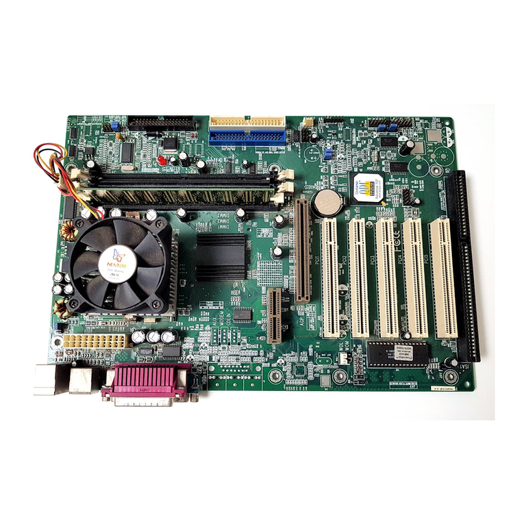
The KinetiZ 7T green mainboard utilizes the VIA Apollo KT-133 chipset, providing a cost-
effective PC/ATX platform with perfect capability and high performance to support Socket
A AMD® DuronTM/AthlonTM processors. The VIA® VT686A chipset integrates software
configurable AC’97 audio gives customers an advanced, multimedia solution at an ex-
tremelylowprice,alsotheKinetiZK7TmainboardintegratesCreativeCT5880PCIhardware
sound(Optional) to provide high quality 3D surrounding sound effect. The VIA® KT-133
chipset provide some new features such as AGP 4X mode and Ultra-Fast 200MHz FSB.
Equippedwiththreememorymodulesockets, 1.5GBPC66/100/133MHzSDRAMand PC100/
133ECCornon-ECCSDRAMDIMMs canbesupported.Italsoprovidesadvancedfeatures
such as wake-up on LAN and wake-up on internal/external modem function. Suspend to
RAM,theoptimalimplementationoftheAdvancedConfigurationandPowerInterface(ACPI)
specification, makes the PC’s power consumption drop to the lowest possible level and
enablequickwakeup.ManageEasy, oursystemmanagementapplicationis alsosuppliedto
enableremotemonitoring and configurationof the system.
Key Features
Form factor
l ATX form factor of 305mm x225mm.
Microprocessor
lSupportsAMDSocket AAthlonTM processorsat700/750/800/850/900/950MHz/
1GHz and further processors.
lSupports AMD Sokcet A DuronTM processors at 600/650/700MHz and further
processors.
lSupports200MHz FSB
lOn-board VDDQ(for AGP), 2.5V regulators and 3.3V switching power supply.
lThree channel power regulators for AMD Socket A AthlonTM/DuronTMProcessors.
Chipset
l Apollo KT-133 chipset: VT8363, VT82C686A.
System memory
lProvidesthree 3.3V 168pin DIMMsockets, supports 1.5GPC66/100/133 ECCor
non-ECCSDRAMDIMMS,VCMSDRAM.
lMinimummemorysizeis8MB,maximummemorysizeis1.5GB.
lSDRAM64bit datainterface with ECCsupport.
On-board IDE
lSupportstwo PCIPIOand BusMaster IDEports.
lTwo fast IDE interfaces supporting four IDE devices including IDE hard disks and
CD-ROMdrives.

Manual for KinetiZ 7T
Introduction
lSupports “Ultra DMA/33”SynchronousDMAmode transferringupto33Mbytes/sec.
lSupports “Ultra DMA/66”SynchronousDMAmode transferringupto66Mbytes/sec.
lIntegrated 16x32bit buffer for IDE PCI Burst Transfers.
On-chipI/O
lOne floppy port supporting up to two 3.5″or 5.25″floppy drives with
360K/720K/1.2M/1.44M/2.88Mformat.
lTwohighspeed16550fastcompatibleUARTs(COM1/COM2/COM3/COM4
selective) with 16-byte send/receive FIFOs.
lOneenabled parallelportat theI/O address378H/278H/3BCHwith additional
bi-directionI/Ocapabilityandmulti-modeasSPP/EPP/ECP(IEEE1284compliant).
lCircuit protection provided, preventing damage to the parallel port when a
connected printer is powered up or operated at a high voltage.
lSupports LS-120 floppy disk drive and Zip drive.
lAllI/Oports canbeenabled/disabled intheBIOS setup.
On-chipAudio
lBuild in VT82C686A
lDirectSound AC97Audio
l AC97 2.1 Compliant
*Creative® CT5880 PCI Hardware Sound(Manufacturing Option)
lPCI2.2compliant
l3D audio effects.
l32-voice XG wavetable synthesizer
lDirect Sound/Music Hardware Accelerator
lFull-Duplexstereo
lSupports four speakers output based on Speaker-out jack and Line-in jack.
AGPSLOT
lSupports4X mode&AGP 2.0compliant.
Advanced features
lPCI2.2Specificationcompliant.
lSupports 3.3V/5V PCI bus interface.
lProvides Trend ChipAwayVirus® On Guard and PC-Cillin software with killing virus
function.
lProvides four USB ports, on-board PS/2 mouse and PS/2 keyboard ports.
lProvides infrared interface.
lSupportPC99color- codingconnectorSpecification.
lSupports Windows 98/Windwos 2000 software power-down.
lSupports wake-up on LAN and wake-up on internal/external modem.
lSupports auto fan off when the system enters suspend mode.

Manual for KinetiZ 7T
lsupportssystemmonitoring(monitorssystemtemperature,CPUtemperature,voltages,
chassis intrusion and fan speed).
lProvidesmanagementapplicationsuchasManageEasy.
lProtects the system BIOS from being attacked by severe virus such as CIH, by
enabling“BIOS-ProtectEasy” inCMOS setupor closingthe Jumper“JAV”.
BIOS
lLicensed advanced AWARD BIOS, supports flash ROM with 2M bit memory size,
plug and play ready.
lSupportsIDECD-ROMorSCSIbootup.
Green function
lSupportsACPI (AdvancedConfigurationand PowerInterface) andODPM (OS
DirectedPowerManagement).
lSupports three green modes: Doze, Standby and Suspend.
lSupports ACPI power status: S0, S1, S3(STR), S5(Soft-off).
Expansion slots
l1 ISA slot
l5PCIslots
l1AGP
l1AMR
Chapter 1

Manual for KinetiZ 7T
Introduction to New Features
BIOS-ProtectEasy
TheBIOSofthemainboardis contained insidetheFlash ROM.Severeviruses suchasCIH
virus are so dangerous that it may overwrite the BIOS of the mainboard. If the BIOS has
been damaged, the system will be unable to boot. We provide the following solution which
protects the system BIOS from being attacked by such viruses.
There are two choices which can implement this function.
1. Set the jumper (JAV) as closed, the BIOS can not be overwritten.
2. Setthejumper(JAV)asopen,meanwhileset“BIOS-ProtectEasy”asEnabledinAWARD
BIOSCMOSSetup.Inthisway,theBIOScannotbeoverwritten,buttheDMIinformation
canbeupdated.
Refer to page 14 for detailed information on jumper setting, and page 22 for related BIOS
setting.
Ultra ATA/66
According to the previous ATA/IDE hard drive data transfer protocol, the signaling way to
send data was in synchronous strobe mode by using the rising edge of the strobe signal.
The Ultra ATA/33 protocol doubles the burst transfer rate from 16.6MB/s to 33.3MB/s, by
using both the rising and falling edges of the strobe signal, this time Ultra ATA/66 doubles
theUltra ATAburst transferrate onceagain (from33.3MB/s to66.6MB/s) byreducing setup
timesand increasingthe stroberate. Thefaster stroberate increasesEMI, whichcannot be
eliminated by the standard 40-pin cable used by ATA and Ultra ATA. To eliminate this
increasein EMI,a new40-pin, 80-conductorcable isneeded.This cableadds 40additional
groundlines betweeneachof theoriginal40 groundandsignal lines.Theadditional 40lines
helpshieldthe signal fromEMI, reduce crosstalkand improves signalintegrity.
Ultra ATA/33 introduced CRC (Cyclical Redundancy Check), a new feature of IDE that
providesdata integrityand reliability.Ultra ATA/66uses thesame process.TheCRCvalue
is calculated by both the host and the hard drive. After the host-request data is sent, the
hostsendsits CRCto the harddrive, and thehard drive comparesit toitsown CRCvalue.
If the hard drive reports errors to the host, then the host retries the command containing
theCRCerror.
Ultra ATA/66 technology increases both performance and date integrity. However there
are basically five requirements for your system to run in Ultra ATA/66 mode:
1. The system board must have a special Ultra ATA/66 detect circuit, such as
KinetiZ7Tmainboard.
2. The system BIOS must also support Ultra ATA/66.
3. The operating system must be capable of DMA transfers. Win95 (OSR2),
Win98 and WindowsNT are capable.
4. An Ultra ATA/66 capable, 40-pin, 80-conductor cable is required.
5. Ultra ATA/66 compatible IDE device such as a hard drive or CD-ROM drive.
Introduction

Manual for KinetiZ 7T
PC-133 Memory
PC133SDRAMUnbuffered DIMMdefinesthe electricalandmechanicalrequirements for
168-pin,3.3 Volt, 133MHz,64/72-bit wide, UnbufferedSynchronous DRAM DualIn-Line
MemoryModules (SDRAMDIMMs). Relatively, the peakbandwidthof PC-133memoryis
the 33% higher than PC-100 memory. These latest SDRAMs are necessary to meet the
enhanced133MHzbusspeedrequirement.
Suspend to RAM
Suspend to RAM is a cost-effective, optimal implementation of the Advanced Configura-
tion and Power Interface (ACPI) 1.0 specification, which makes a PC’s power consump-
tion drop to the lowest possible level and enables quick wakeup. When the system is in
Suspend-to-RAMstatus,the systemcontext is maintainedin system memory,the system
consumes only a small fraction of the power used for full operation. Instead of shutting
down the system to save power when not in use and then having to reboot later, Sus-
pend-to-RAM solution enables the system to quickly wake up, restoring all applications
and features, enabling operation in a few seconds.
Toimplement thisfunction, thefollowing requirmentsareessential:
1. Power supply requirements: The current of 5VSB line of the power supply should be
morethan0.75A.
2. Set the Jumper J13 with pin1&pin2 closed. Refer to page 13 for detailed information.
3. TheBIOS option“ACPIfunction”shouldbe enabled,and“ACPI SuspendType”should
be set as S3 in AWARD BIOS CMOS setup. Refer to page 28 for detailed information.
4. An ACPI-enabled operating system such as Windows 98 or Windows 2000 family is
needed.NavigatetotheCD-ROMdrivefromtheMS-DOSCommandPromptandenter
the following from the Win98 directory on the CD:
D:\SETUP /P J
(This manual assumes that your CD-ROM device driver letter is D:)
Windows 98 will be installed with ACPI enabled.
For Windows 98 SE and Windows 2000, just install them directly.
5. Three ways to enter Suspend-to-RAM status under ACPI-enabled Windows 98:
lClick Start -> Shut down -> Standby to enable the system to enter Suspend-to-
RAMstatus.
lClick Start -> Setup -> Control Panel -> Power Management -> Advanced and
choose Standby item, the system will enter Suspend-to-RAM status when you
press power button.
lFrom Power Management Properties in Control Panel, set the latency time in
System Standby, the system will enter Suspend-to-RAM status when time out.
The same ways used to power up the system can be used to wake up the system from
Suspend-to-RAM status. For example, pushing the power button, through the Wake-on-
LAN,Wake-on-Modemfunction orRTCAlarm.
Introduction Chapter 1

Manual for KinetiZ 7T
Creative CT5880 chipset
TheCT5880provideshigh-qualityaudioperformanceandlowCPUutiliaztionforyou.
Featuring 128-vioce wave-table synthesis with very high sample rate converters. In
addition, CT5880 supports localized three-dimensional sound immersion in headphone
andfour-speakerenvironments. The four-speakerbased on speaker-outand line-in jack.
the CT5880 also supports multiple algorithm levels of reverb and chorus effects on the
wave-table sounds as well as spatial sound enhancement on MIDI and wave sounds in
two speakers. Full duplex operation also allows simultaneous audio recording and play-
back.
The KinetiZ 7T mainboard has two solution for on-board sound.
Note: If Creative® CT5880 chip is onboard, the slave card must be installed in
the first PCI slot.
Installation of CT5880 driver
Beforeyou install CT5880chipset driver, pleasemake surethat CT5880chipset is onboard.
1.If CT5880 chipsetis onboard, theCD2000 willdetected itandthe option“ PCI Sound
Driver” will appear on screen, you click this option to install CT5880 chipset driver .
2. If CT5880 is not onboard, the CD 2000 will detected AC97codec and the option “ Audio
Codec Driver” will appear on screen, you click this option to complete the installation
Soft-sound(AC’97codec)
Hardware-sound(CT5880)(Option)
Note:After installation ofCT5880dirver, you
can select four speaker output function
Introduction

Manual for KinetiZ 7T
Chapter 2
Installation Instructions
Chapter 2
Installation Instructions
This section covers External Connectors and Jumper Settings. Refer to the mainboard
layout chart for locations of all jumpers, external connectors, slots and I/O ports. Further-
more, this section lists all necessary connector pin assignments for your reference. The
particular state of the jumpers, connectors and ports are illustrated in the following figures.
Before setting the jumpers or inserting these connectors, please pay attention to the direc-
tions.
Be sure to unplug the AC power supply before adding or removing expansion
cards or other system peripherals, otherwise your mainboard and expansion
cards might be seriously damaged.
External Connectors
PS/2 Keyboard Connector, PS/2 Mouse Connector
PS/2 keyboard connector is for the usage of PS/2 keyboard. If using a standard AT size
keyboard, an adapter should be used to fit this connector. PS/2 mouse connector is for the
usageof PS/2mouse.
USB1,USB2
Two USB ports are available for connecting USB devices.
USB3,USB4
Two USB ports are not available on the back panel. Therefore, we provide a 10-pin ribbon
cable with bracket to connect Built-in on-board USB header. ( manufacturing option)
chapter 2
PS/2 Mouse Connector
PS/2 Keyboard Connector
USB1
USB2
+5v
T1-
T1+
GND
GND
GND
GND
T0+
T0-
+5v

Manual for KinetiZ 7T
Parallel Port Connector and Serial Port Connector (UART1)
The parallel port connector can be connected to a parallel device such as a printer, while
the serial port connector can be connected to a serial port device such as a serial port
mouse. You can enable/disable them and choose the IRQ or I/O address in “Integrated
Peripherals”fromAWARD BIOS SETUP.
UART2
The serial port UART2 is not available on the back panel. Therefore, we provide a 9-pin
ribbon cable with bracket for UART2 port. (manufacturing option)
Line-in jack(or Rear out jack), Microphone-in jack, Speaker-out jack
and
MIDI/Joystick connector
The Line-in jack can be connected to devices such as a cassette or minidisc player for
playbackor recording.TheMicrophone-in jackcan beconnected toa microphone forvoice
input. The Speaker-out jack allows you to connect speakers or headphones for audio
outputfrom theinternal amplifier.
Note: if you choose four speaker output in CT5880 configuration, the Rear out
jack replaces Line-in jack to connects powered speakers for audio output.
The MIDI/Joystick connector allows you to connect a game joystick or a MIDI device.
Installation Instruction
MIDI/Joystick
Speaker outLine in(or Rear out ) jact
Microphonein
Parallel Port
UART1
1
UART2

Manual for KinetiZ 7T
ATX Power Supply Connector & Power Switch (POWER SW)
Be sure to connect the power supply plug to this connector in its proper orientation. The
power switch (POWER SW) should be connected to a momentary switch (power button).
When powering up your system, first turn on the mechanical switch of the power supply (if
one is provided), then push once the power button. When powering off the system, you
needn’t turn off the mechanical switch, just Push once*the power button.
Note: * If you change “soft-off by PWR-BTTN” from default “Instant-off” to “Delay
4 Secs” in the “POWER MANAGEMENT SETUP” section of the BIOS, the power
button should be pressed for more than 4 seconds before the system powers
down.
Hard Disk LED Connector (HD LED)
Theconnector connects tothe case’sIDE indicator LEDindicating theactivity status ofIDE
hard disk. The connector has an orientation. If one way doesn’t work, try the other way.
Reset Switch (RESET)
The connector connects to the case’s reset switch. Press the switch once, the system
resets.
Speaker Connector (SPEAKER)
The connector can be connected to the speaker on the case.
ACPI LED Connector (ACPI_LED)(Reserved)
TheACPI LEDisdouble-color lightswith threepins. Pin1&Pin2drive differentcolor lights.If
Pin1 drives the yellow light , Pin2 drives the green light, the following status will come out.
Whenthe systemisinpowerup status,the LEDisgreen on.When thesystemis insuspend
status, the LED is green blink. When the system is in suspend to RAM status, the LED is
orange on. When the system is in soft-off status, the LED is off.
GREENLED Connector(GREEN_LED)
The GREEN LED has five status. When the system is in three status (including power up,
suspend, soft-off), the LED is off. When the system is in suspend to RAM status, the LED
is on. When the system is in APM(advanced power management), the LED is on.
Hardware Green Connector (SLEEP)
Push once the switch connected to this header, the system enters suspend mode.
POWER
SW
ATX Power Supply Connector
1
20
3.3V -12V GND PSON GND GND GND -5V 5V 5V
3.3V 3.3V GND 5V GND 5V GND PS-OK 5VSB 12V
chapter 2

Manual for KinetiZ 7T
Power LED Connector (PWRLED)
The power LED has four status. When the system is in power up status, the LED is on.
Whenthesystem is in suspendstatus, the LED isblink. When thesystem is inSuspend to
RAM,the LEDisoff. Whenthe systemisin Soft-Offstatus, theLEDisoff.Theconnector has
anorientation.
Key-LockConnector(KEY_L)
The connector can be connected to the keyboard lock switch on the case for locking the
keyboard.
Fan Connector (CPUFAN, CHSFAN. FAN3)
These connectors support cooling fans of 35ma or less. Besides speed of the FAN3, The
speeds of the CPU fan and chassis fan can be detected and viewed in “PC Health Status”
sectionofthe BIOS, .They will beautomatically turned offafter thesystementers suspend
mode.
HDLED
SPEAKER
ACPI_LED
RESET
Power
SW SLEEP
GREEN_LED
POWER_LED
KEY_L
HDDLED +
HDDLED
SPKDATA
NC
GND
VCC
HDDLED
SPEAKER
GND
RE-
RESET
EMPTY
LED
LED
LED
Green_LED
KEYLOCK
GND
KEY_L
LED1 -
LED2 -
LED+(VCC)
POWER
GND
EMPTY
LED
LED -
LED -
SLEEP
GND
EMPTY
ACPI
LED Power SLEEP POWER
LED
FAN GND
+12V
SENSE
FNA3
CHSFAN
FAN GND
+12V
SENSE
FAN GND
+12V
SENSE
CPUFAN
Installation Instruction

Manual for KinetiZ 7T
Internal Audio Connectors (AUX, CDLIN, MODEM)
AUX and CDLIN connectors allow you to receive stereo audio input from such sound
sourcesasaCD-ROM,TVtuner,orMPEGcard.TheMODEMconnectorallowstheonboard
audio to interface with a voice modem card with a similar connector. It also allows the
sharing of mono_in (such as a phone) and mono_out (such as a speaker) between the
onboard audio and the voice modem card.
Audio/Modem Riser Interface Connector (AMR)
TheAMRInterfaceConnectoristheinterfacebetweenthemainboardandtheAudio/Modem
Riser card. The connector provides all necessary signals which supports several different
configurations of audio and modem in the system, such as audio and modem on the Riser,
audio on the mainboard and modem on the Riser, or no audio with modem on the Riser.
KinetiZ 7A mainboard provides you with audio onboard solution, onboard audio can be
enabled/disabled.EitherAMR(Audio/Modem Riser)cardorMR(Modem Riser)cardcanbe
used on this system. This software configurable AC’97 audio and modem system gives
customersanadvanced,multimediasolutionatanextremelylowprice.TheAC’97audioand
modemsystemcanbeenabled/disabledin“IntegratedPeripherals”inAWARDBIOSCMOS
Setup.
CDLIN
Common
CD Right Channel CD Left Channel
GNDPhone-In (from Modem)
Mono-Out (to Modem)
MODEM
Right Audio Channel
AUX
GND LeftAudioChannel
AMR Interface Connector
chapter 2

Manual for KinetiZ 7T
Wake-Up On Internal Modem (WOM)
Through the Wake-Up On Internal Modem function, the system which is in the power-off
statuscanbe poweredon by aring signal receivedfrom theinternalmodem. Ifthis function
is to be used, be sure an internal modem card which supports the function is used. Then
connect this header to the relevant connector on the modem card, set “Wake Up On LAN/
Ring” asEnabledinthe“POWERMANAGEMENTSETUP”sectionoftheBIOS.Save&exit,
then boot the operating system once to make sure this function takes effect.
Wake-Up On LAN (WOL)
Through the Wake-Up On LAN function, a wake event occurring from the network can
wake up the system. If this function is to be used, please be sure an ATX 2.01 power
supply of which 5VSB line is capable of delivering 720mA, and a LAN adapter which
supports this function are used. Then connect this header to the relevant connector on the
LANadapter,set“PowerOnbyRing/LAN”asEnabledinthe“POWERMANAGEMENTSETUP”
section of the BIOS. Save & exit, then boot the operating system once to make sure this
function takes effect.
Infrared Header (IrDA)
This connector supports wireless transmitting and receiving. If using this function, set
“UART 2 Mode” to HPSIR or ASKIR and configure the settings from the “INTEGRATED
PERIPHERALS”sectionoftheBIOS.
1
1
+5Vstandby
GND
Signal for waking up (active low)
+5Vstandby
GND
Signal for waking up (active high)
Installation Instruction
VCC
NC
IRRX
GND
IRTX
VCC
Table of contents
Other QDI Motherboard manuals