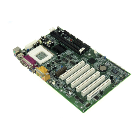
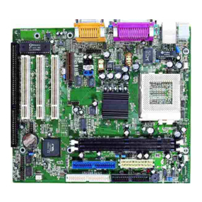
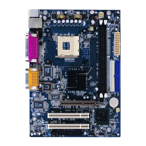
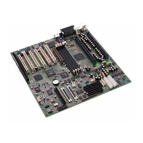
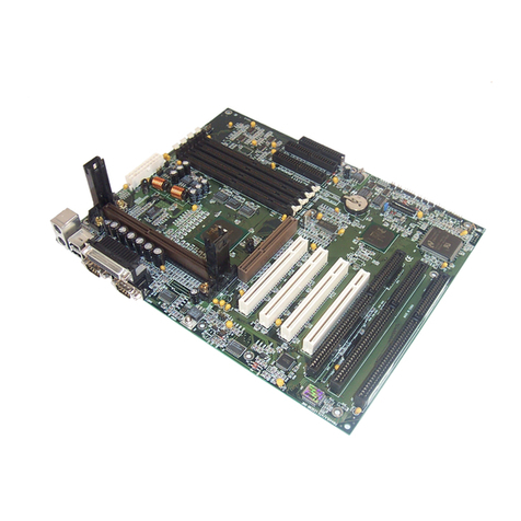
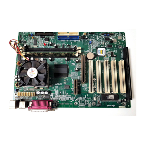
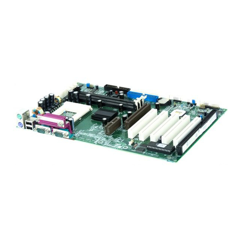
QDI SynactiX 2EP User manual

Notice
The information in this document is subject to change in order to improve reliability, design,
or function without prior notice and does not represent a commitment on the part of this
company. In no event will we be liable for direct, indirect, special, incidental, or consequen-
tial damages arising out of the use or the possibility of such damages.
All trademarks are the property of their respective owners.
If you require further information, please visit our web-site: “www.qdigrp.com”.
Item Checklist
Completely check your package. If you discover damaged or missing items, contact your
retailer.
SynactiX 2EP mainboard
QDI Driver Utility CD
I/O shield(optional)
1 ATA 100/66 cable
1 FDD cable
1 COM2 cable(optional)
QDI Serial Product R.M.A. Warranty Card
User’s manual

Declaration of conformity
QUANTUMDESIGNS(HK)LTD.
20th Floor, Devon House, TaiKoo Place 979 King’s Road,
Quarry Bay, Hong Kong
declares that the product
Mainboard
SynactiX 2EP
is in conformity with
(reference to the specification under which conformity is declared in
accordance with 89/336 EEC-EMC Directive)
þ EN 55022 Limits and methods of measurements of radio disturbance
characteristics of information technology equipment
þ EN 50081-1 Generic emission standard Part 1:
Residential, commercial and light industry
þ EN 50082-1 Generic immunity standard Part 1:
Residential, commercial and light industry
European Representative:
QDICOMPUTER(UK)LTD QDI COMPUTER ( SCANDINAVIA ) A/S
QDISYSTEMHANDELGMBH QDICOMPUTER(NETHERLANDS)B.V.
QDICOMPUTER(FRANCE)SARL QDICOMPUTERHANDELSGMBH
QDICOMPUTER(ESPANA)S.A. QDICOMPUTER(SWEDEN)AB
Signature : Place / Date : HONG KONG/2000
Printed Name : Lv Yan Position/ Title : Assistant President

Declaration of conformity
Trade Name: QDI Computer ( U. S . A. ) Inc.
Model Name: SynactiX 2EP
Responsible Party: QDI Computer ( U. S. A.) Inc.
Address: 41456 Christy Street
Fremont, CA 94538
Telephone: (510) 668-4933
Facsimile: (510) 668-4966
Equipment Classification: FCC Class B Subassembly
Type of Product: Mainboard
Manufacturer:Quantum Designs (HK) Inc.
Address: 20th Floor, Devon House, TaiKoo Place
979 King’s Road, Quarry Bay, HONG
KONG
Supplementary Information:
This device complies with Part 15 of the FCC Rules. Operation is subject to
the following two conditions : (1) this device may not cause harmful interfer-
ence, and (2) this device must accept any interference received, including
interference that may cause undesired operation.
Signature : Date : 2000

CONTENTS
BootEasy(English).................................................................................S.1
BootEasy .............................................................................S.2
SpeedEasyQuickSetup(English).................................................... S.3
SpeedEasy ............................................................... S.5
Facilitédevitesse Initialisation(Francais) .......................................... S.7
1. Introduction................................................................. 1
Overview............................................................................................ 1
KeyFeatures ...................................................................................... 1
Introduction to New Features .............................................................. 4
2. Installation Instructions .............................................. 7
External Connectors ................................................................. 7
PS/2Keyboard/MouseConnector ........................................................ 7
USB1& USB2and LANconnector ....................................................... 7
ParallelPort,SerialPort Connector ...................................................... 7
Line-in,Microphone-in,Speaker-outjackandMIDI/Joystickconnector.. 7
UART2,USB3,4 ................................................................................... 8
ATXPowerSupply Connector&Power Switch(POWERSW) .............. 8
HardDiskLEDConnector(HD_LED) .................................................... 9
ResetSwitch(RESET)......................................................................... 9
SpeakerConnector(SPEAKER)........................................................... 9
PowerLEDConnector(PWRLED) ....................................................... 9
ACPI LEDConnector(ACPILED) ......................................................... 9
GREENLEDConnector(GREENLED) ................................................... 9
HardwareGreenConnector(SLEEP SW) ............................................ 9
Key Lock Connector (KEY LK) ............................................................ 9
InfraredHeader (IrDA)....................................................................... 10
Fan Connector(PWRFAN,CPUFAN,CHSFAN) ................................... 10
Wake-UpOnLAN(WOL) ................................................................... 10
Wake-UpOnInternalModem(WOM) ...................................................11
AudioConnector(CDLIN1,MODEM) ....................................................11
SoundConnector(PC-PCI)..................................................................11
4pinSMBusConnector(SMBUS) ....................................................... 12
ChassisSecurity Switch(CHSSEC) .................................................. 12
CommunicationandNetworkingRiserInterfaceConnector(CNR) ....... 12
ExpansionSlots &I/O Portsdescription ............................................. 13
I

CONTENTS
Jumper Settings ...................................................... ....... 13
ClearCMOS ..................................................................................... 14
Enable/Disableon-boardaudio(JSD) ................................................. 14
Enable keyboard password power-on function(JKB) ...................... 14
ConnectPCI3.3VSBVoltageJumper(JSB) ........................................ 15
OverclockingJumperSetting(JFS0,JFS1)......................................... 15
BIOSProtectionJumper(JAV) ........................................................... 16
OnboardLanJumper(JP25) ............................................................... 17
EnableFront/BackPanelUSBDeviceWake-upFunction(JFUSB/JUSB)17
MemoryConfiguration........................................................................ 18
Installation of All Drivers (EASY!) ....................................................... 18
PC-cillin ............................................................................................. 19
QDIManageEasy ............................................................................... 19
AdditionalInformation ........................................................................ 19
3.BIOS Description .............................................................. 21
UtilitySupport ........................................................................... 21
AWDFLASH.EXE ............................................................................... 21
AWARD BIOS Description........................................................ 21
EnteringSetup................................................................................... 22
LoadOptimizedDefaults.................................................................. 22
StandardCMOSFeaturesSetup ...................................................... 22
CPUSpeedEasySetup ...................................................................... 26
AdvancedBIOS FeaturesSetup ...................................................... 27
AdvancedChipsetFeatures Setup .................................................. 29
PowerManagementSetup............................................................... 31
PNP/PCIConfigurationSetup ............................................................ 33
IntegratedPeripherals...................................................................... 34
PCHealthStatus................................................................................ 36
Password Setting............................................................................. 38
Boot with BIOS defaults .................................................................. 38
Appendix A QDI Driver UtilityCD ................................................ 39
Appendix B Boot Logo............................................................... 40
RecoveryEasy.................................................................41
II

Manual for SynactiX 2EP
Be sure to unplug the AC power supply before adding or removing
expansion cards or other system peripherals, especially the SDRAM
memory, otherwise your mainboard or the system memory might be
seriously damaged.
The power status of the system is indicated by the red LED near the battery.
If the LED is on, adding or removing devices like SDRAM memory is prohib-
ited.
Caution 1
Caution 2
Be sure to add some Silicone Grease between the PentiumIII
(Coppermine) CPU and the FAN to keep them fully contact , meanwhile
to meet the heat sink requirement.

Manual for SynactiX 2EP
QDI BootEasy
BootEasy is a new member of legend QDI Easy series, which is the latest
innovation comes from legend QDI.
Figure - 1 BootEasy Setup Menu
BootEasy technology enormously improves the long BOOT process time of com-
puters. Reducing the wait time every user has to suffer when starting their com-
puter. BIOS without BootEasy has to perform many routines every times when the
system starts, such as checking system core of the computer and initializing
system peripherals. Now with the BootEasy, BIOS will not run these repetitive
Processes any longer , PC can boot-up without any redundant waiting for the
displaying of starting OS. BootEasy is quite easy to use , choose the right option
in CMOS SETUP, ( refer to Advanced BIOS Features) it can be easily booted
quickly. BootEasy save all the information when PC first normally boot-up, and it
restores all the parameters for the system and thus let the PC boot freely and
rapidly.
Note:
1. Under the following conditions, PC will boot-up in normal way.
(1) PC boot-up for the first times after set option as Enabled.
(2) the system information saved by BIOS was damaged.
(3) PC fail to boot-up continually over three times.
2. Don’t power off or reset system while BootEasy initializing.
3. set “QDI BootEasy Feature” as “Disabled” before you replace system equipment.
set “QDI BootEasy Feature” as “Enabled” after you accomplished replacing.
S.1
SynactiX 2EP

Manual for SynactiX 2EP
QDI BootEasy
BootEasy QDI Easy QDI
BootEasy
BootEasy
BootEasy
BIOS BootEasy Advanced BIOS Features
QDI BootEasy Feature BootEasy
Enabled BIOS
BootEasy
BIOS
1 BootEasy Enabled
2BIOS
3
RESET
QDI BootEasy Feature
Disabled Enabled
1 BootEasy
S.2
BootEasy

Manual for SynactiX 2EP
SpeedEasy Quick Setup
Procedures :
1. CorrectlyinserttheIntel®PentiumIIIFC-PGA,CeleronFC-PGAor Celeron PPGA
370 processors.
2. Plug in other configurations and restore the system.
3. Switch on power to the system and press the <Del> key to enter BIOS Setup.
4. Enter“CPU SpeedEasySetup” menuto setuptheCPUspeed.
Note: If you do not set the CPU speed, your system will run at the default
setting (400MHz processor with 133MHz host bus speed, 300MHz
for processor with 100MHz host bus speed, 200MHz for processor
with 66MHz host bus speed, for bus ratio locked processor, run its
real speed.
5. Save and exit BIOS Setup, your system will now boot successfully.
S.3
SynactiX 2EP

Manual for SynactiX 2EP
CPU SpeedEasy Setup Menu
Select<CPUSpeedEasySetup>itemfrom themainmenuand enterthesub-menu:
Figure-1CPU SpeedEasySetupMenu
BIOS provides you with a set of basic values for your processor selection instead of the
jumpersettings.The processorspeed can bemanually selected onthe “CPUSpeedEasy
SETUP”menuscreen.
Warning:
Do not set CPU frequency higher than its working frequency. If you do, we will
not be responsible for any damages caused.
S.4
SpeedEasy Type Introduction

Manual for SynactiX 2EP
Intel®PentiumIIIFC-PGA,CeleronFC-PGA CeleronPPGA370
Del BIOS
CPU SpeedEasy Setup
133
CPU 400 100 CPU 300 66
CPU 200 CPU
BIOS
S.5
SynactiX 2EP

Manual for SynactiX 2EP
SpeedEasy
CPU SpeedEasy Setup
SpeedEasy
BIOS jumper
CPU SpeedEasy Setup
S.6
SpeedEasy

Manual for SynactiX 2EP S.7
SynactiX 2EP
Installation de la carte mère SynactiX 2EP
1. Assurez-vous que votre ensemble est complet: carte mère, câbles IDE et FLOPPY,
noticed’utilisationetCD-ROMd’installation.
2. Vérifiez que l’alimentation est débranchée et reliez-vous à la terre par une courroie
à votre poignet. A défaut, maintenez le contact de vos deux mains avec un objet lui-
même relié à la terre, ou une partie en métal de votre système.
3. Fixez la carte mère dans le boîtier grâce aux vis fournies avec celui-ci.
4. Si votre carte mère est munie de cavaliers, placez les en fonction des options que
vous souhaitez utiliser: réglage de la fréquence du processeur si votre carte n’est
pas SpeedEasy, fonction allumage par saisie du mot de passe…(voir le manuel,
rubrique «configuration des cavaliers» pages 16 à 19)
5. Insérez le processeur dans son logement avec son ventilateur que vous
brancherezauconnecteur«CPUFAN».
6. Insérezla/lesbarrette(s)mémoiredans lesslots DIMM.
7. Installez vos éventuelles cartes PCI et AMR dans les slots prévus à cet effet (voir
pagecentrale dumanuel).
8. Branchez vos périphériques IDE et FLOPPY sur les connecteurs prévus à cet effet
grâce aux nappes fournies avec la carte. Vérifiez que le sens de branchement est
correct (liseré rouge du câble sur la broche 1 du connecteur).
9. Reliez les câbles du boîtier aux connecteurs prévus à cet effet (Connecteur
d’alimentation,LEDdemarche/arrêt,disquedur,haut-parleur…voirmanuelpages 11
à15). Refermez leboîtier.
10. Branchez les périphériques externes sur les sorties du fond de panier: clavier,
sourisPS/2,périphériquesUSB, moniteur,imprimante…(voirmanuel pages9-10)
11. Lorsque tous les éléments du système sont installés physiquement, rebranchez
l’unitécentrale.
Installation du système.
1. Démarrezvotre systèmeen pressantle bouton«POWER».
2. Pressez la touche «Suppr» pour entrer dans le setup du BIOS.
3. Dans le menu «SpeedEasy CPU Setup», réglez la vitesse de votre processeur
(ATTENTION: ilest recommandéde nepas sélectionnerune fréquencesupérieure à
celle de votre processeur, nous déclinons toute responsabilité pour les dommages
quienrésulteraient)

Manual for SynactiX 2EP
Installation du SynactiX 2EP système
S.8
4. Effectuez les autres réglages du BIOS selon votre configuration (nous vous
conseillons fortement de maintenir les réglages par défaut afin d’éviter toute
manipulationhasardeusepouvant résulterenun dysfonctionnement).Pour plus
d’informations sur les fonctions du BIOS, vous pouvez consulter la version
françaisedu manuelsurle CD-ROM.
5. Pressez la touche F10 ou choisissez «Save and exit» pour enregistrer vos
paramètreset relancer lamachine.
6. Installezvotre systèmed’exploitation
7. Après installation, assurez-vous qu’il ne subsiste aucun conflit ou périphérique
inconnu dans votre système.
8. Installationdespilotes:
ØLogiciel Demo Shield
Un logiciel qui vous apporte une nouvelle interface plus conviviale et facile
à utiliser.
ØPoint-and-Click
Placez simplement la souris sur l’option que vous désirez et cliquez , le pilote
ou le logiciel dont vous avez besoin s’installe automatiquement.
ØIntelligently Recognition
Reconnaissance automatique du matériel et installation des pilotes
nécessaires pour les composants intégrés.
Express Install
Ilest recommandé d’installerles programmesavec lesoptionsles pluscommunes.
A. Intel INF
B. Piloteréseau
C. Piloteaudio
Redémarrez l’ordinateur après installation des pilotes son, le système trouvera un
périphériqueSon,cliquez sur« Suivant » jusqu’à« Terminer »et lepériphérique son
fonctionneranormalement. N’oubliezpas deredémarrer unenouvelle foisl’ordinateur !
Note : si vous cliquez sur « Annuler » au lieu de « Suivant » pendant la procédure ci-
dessus, le périphérique son risque de ne pas être détecté, redémarrez alors l’ordinateur
et reprenez la procédure ci-dessus.

Manual for SynactiX 2EP S.9
SynactiX 2EP
1. Accessory
Les logiciels contenus dans ce répertoire sont :
A. DirectX7.0
B. QDIManageEasy
C. PC-Cillin
2. Browse CD
Vouspouvez voir lecontenu duCD-ROM
Dansle répertoireUtility :
A. AWDFLASH.EXE
B. CBLOGO.EXE
C. LF.EXE
3. Dans le répertoire Documents :
A. Adobe Acrobat Reader V3.0 – Ar32e301.exe
B. Manuels français des cartes mères
QDI BootEasy
BootEasyest la dernièrenée destechnologies Legend QDI.
Voir figure 1 page S.1 du manuel en anglais.
BootEasypermet auPC dedémarrer plusrapidement lorsqu’onallume, resetou relancele
PC.
Ils’agitd’une véritabletechnologie «OnNow» et «Instantlyavailable PC»,conforme aux
spécificationsPC2001.
BootEasy est facile à utiliser, il suffit de choisir l’option correcte dans le menu «Advanced
BiosFeatures Setup».
BootEasysauvegarde toutesles informationslorsquelePCbootenormalementet
restaurelesparamètres pourle système, permettantainsi au PCde démarrerrapidement.
Note:
1. Le PC démarre de manière classique dans les cas suivants:
-Premier démarrageaprès activationde l’optionBootEasy
-Informationssauvegardéesendommagées
- Echec au démarrage du PC à 3 reprises
2. N’arrêtez pas ou ne redémarrez pas le système lorsque BootEasy s’initialise
3. Placez«QDIBootEasy Feature»sur «Disabled»avant dechanger uncomposantdu
système
Placez«QDI BootEasy Feature»sur «Enabled»après avoireffectuéle changement.

Manual for SynactiX 2EP
Installation du SynactiX 2EP système
S.10
Le menu SpeedEasy
I. Insérez le processeur correctement.
II. Connectez les autres éléments du système (voir Installation).
III. Au démarrage du système, pressez la touche <Suppr> pour entrer dans
le Bios
IV. Entrez dans le menu «CPU SpeedEasy setup»
Note: si vous ne déterminez pas la vitesse de votre unité centrale, votre
systèmefonctionnerapardéfaut( 200MHz pour les CPUavecune
fréquence de Bus de 100MHz et 133MHz pour les CPU à 66MHz).
V. Sauvegardez et quittez le Bios.
Le menu SpeedEasy vous fournit un ensemble de valeurs. Vous pouvez
sélectionner manuellement la vitesse de CPU dans ce menu soit en mode
“SpeedEasy” soit en mode “Jumper Emulation” (voir manuel).
ATTENTION: Nepassélectionner unefréquence defonctionnementduCPU
supérieure à celle indiquée par le constructeur. Nous déclinons toute
responsabilité pour tout dégât qui en résulterait.
CMOS Setup Utility – Copyright© 1984-1999 Award Software
SpeedEasy CPU Setup
CPU Model : Intel® Celeron™ Item Help
CPU Speed : 433 Mhz (66x6.5)
X Multiplier X2 Menu Level >
X Bus Clock 66MHz
Spread Spectrum Disabled

Manual for SynactiX 2EP
Chapter 1
Introduction
Chapter 1
Chapter 1
Introduction
Overview
SynactiX 2EP green mainboard utilizes Intel® 815EP chipset, 815EP contains two
components:the82815EP MemoryController Hub(MCH)and the82801BAI/OController
Hub2(ICH2). providing a fully compatible, high performanced and cost-effective PC/ATX
platform. The new integrated technologies, together with AGP 4X support, the software
configurable AC’97 audio(support up to 6 channels by CNR), integrated LAN(optional), 4
USB ports, and ATA100/66/33 give customers an advanced, multimedia solution at an
extremelylow price.Itprovides 66/100/133MHz systembus tosupport all Intel®Pentium
IIIFC-PGA, CeleronFC-PGA andCeleronPPGA370processors. 100/133MHzSDRAMs
are supported up to 512MB. It also provides advanced features such as Wake up by USB
devices, Wake-on-LAN, Wake-on-Modem and Keyboard Password Power-on functions.
Suspend to RAM, the optimal implementation of the Advanced Configuration and Power
Interface (ACPI) specification, makes the PC’s power consumption drop to the lowest
possibleleveland enablequickwakeup. ManageEasy,our system managementapplica-
tion is also supplied to enable remote monitoring and configuration of the system.
Key Features
Form factor
l ATX form factor of 305mm x 210mm.
Microprocessor
l Supports allIntel® PentiumIII(Coppermine) FC-PGAprocessorsat533/600/667/733/
800/866/933MHz/1GHz and future processors with 133MHz bus speed.
l Supports allIntel® PentiumIII(Coppermine) FC-PGAprocessorsat500/550/600/650/
700/750/800/850MHz and future processors with 100MHz bus speed.
l SupportsallIntel®Celeron™FC-PGAprocessorsat533/566/600/633/667/700/733MHz
and future processors with 66MHz bus speed.
l Supports all Intel® Celeron™ PPGA processors at 300/300A/333/366/400/433/466/
500/533MHzwith 66MHzbusspeed.
l Supports 66/100/133MHz host bus speed.
l CPU core frequency = Bus speed x3, x3.5, x4, x4.5, x5, x5.5, x6, x6.5, x7, x7.5, x8,
x8.5, x9, x9.5, x10, x10.5, x11, x11.5, x12.
l The CPU core voltage adjustable from 1.3V to 2.0V automatically through onboard
switching voltage regulator with VID(Voltage ID).
System memory
l Provides three 168 pin 3.3V unbuffered DIMM sockets.
l Supports64-bit wide DIMMmodules with100/133MHz SDRAMdevices.
l Supports32MBto256MBSDRAMusing16Mb/64Mb/128Mbtechnology.

Manual for SynactiX 2EP
Introduction
l Supports512MBSDRAM using256Mb technology.
l Supports up to three double-sided DIMMs(6 Rows) at 100MHz system memory bus.
l Supportsuptotwodouble-sided orthreesingle-sided DIMMs(4RowsMax) at133MHz
systemmemorybus(PC-133).
Onboard IDE
l Supports Independent timing of up to 4 drives.
l SupportsUltraATA/100/66/33,BMIDEand PIOmodes.
l Read transfers up to 100MB/s, Writes to 89MB/s.
l Seperate IDE connections for Primary and Secondary cables.
l Implements Write Ping-Pong Buffer for faster write performance.
l Two fast IDE interfaces supporting four IDE devices including IDE hard disks and CD-
ROMdrives.
l Integrated 16x32bit buffer for IDE PCI Burst Transfers.
OnboardLAN
l 10/100 Mbit/sec Ethernet support.
l 10/100M LAN interface built-in on-board(optional).
4 USB
l 2 UHCI Host Controllers with a total of 4 ports.
l USB 1.1compliant.
l Supports wake-up from sleeping states S1-S3.(depend on device)
Onboard I/O
l WinbondW83627HFLPCI/Ochip.
l One floppy port supporting up to two 3.5″or 5.25″floppy drives with 360K/720K/1.2M/
1.44M/2.88Mformat.
l Two highspeed 16550compatible UART (COM1/COM2/COM3/COM4selective) with
16-bytesend/receive FIFOs.
l One joystick port.
l Infrared interface.
l All I/O ports can be enabled/disabled in the BIOS setup.
Onboard Sound
l AC’972.1 SpecificationCompliant.
l 18bit stereo codec.
l Multiplestereo input mixer.
l Mono and stereo volume control.
l Provides onboard Line-in Jack, Microphone-in Jack, Speaker-out Jack and MIDI/Joy-
stickConnector.
AGP Interface
l AGP Universal Connector supports AGP 2.0 including 4x AGP data transfers.

Manual for SynactiX 2EP
Chapter 1
Advanced features
l PCI 2.2SpecificationCompliant.
l Provides Trend ChipAwayVirus On Guard.
l Provides PC-Cillin software with killing virus function.
l Supports Windows 95/98/2000 software power-down.
l SupportsWake-on-LAN andWake-on-Modem.
l Supports Keyboard Password Power-on function.
l Supports system monitoring(monitors CPU and system temperatures, system volt-
ages, chassis intrusion and fan speed).
l System status resumes after AC power failure.
l Provides onboard 3.3V regulator to support ATX power supply without 3.3V output.
(Optional)
l Provides onboard 1.5V, 1.8V, 2.5V and 3.3V standby regulator.
l Supports management applications such as QDI’s ManageEasy or LDCM (LANDesk
ClientManager).(optional)
l ProvidingQDI’sinnovationssuch asSpeedEasy,RecoveryEasy,BIOS-ProtectEasy(to
protectthesystem BIOSfrombeingattackedbyseverevirussuchasCIH),LogoEasy,
ManageEasy and BootEasy(new feature).
BIOS
l Licensed advanced AWARD BIOS, supports flash ROM with 4Mb memory size, plug
and play ready.
l SupportsIDECD-ROMorSCSIbootup.
Green function
l Supports ACPI (Advanced Configuration and Power Interface) and ODPM (OS
Directed Power Management).
l Supports five ACPI power status: Full-on, Stop Grant, Suspend to RAM, Suspend to
Harddisk(Windows Me, Windows 2000) and Soft-off.
Expansion slots
l 1 AGP slot.
l 6 PCI slots.
l 1 CNR slot.

Manual for SynactiX 2EP
ESD(Electrostatic discharge) Protection:
This mainboard provides a very high level of protection for sensitive electronic compo-
nentsthatmay besubjectedto electrostatic discharge(ESD),especially for I/Oports such
as PS2 connectors or USB port. The ESD components that complies with IED61000-4-2
(level 4) (up to 25kv) and MIL STD883C-Method 3015-6 Class-3 are populated on the
mainboard to prevent the system from resetting or hanging even serious damaging by
static electricity.
BIOS-ProtectEasy
TheBIOS ofthemainboardisinside theFWH. Somesevere virusessuch asCIH virusare
so dangerous that it may overwrite the BIOS of the mainboard. If the BIOS has been
damaged, the system will be unable to boot. We provide the following solution which
protects the system BIOS from being attacked by such viruses.
Here are two choices to implement this function,
1. Setthe jumper (JAV)as closed, theBIOS cannot beoverwritten and theDMI informa-
tion can not be updated either.
2. Set the jumper (JAV) as open, meanwhile set “Flash Write Protect” as Enabled in
AWARDBIOSCMOS Setup.In thisway, theBIOS cannot beoverwritten, butthe DMI
information can be updated.
Refer to page 16 for detailed information on jumper setting, and page 28 for related
BIOSsetting.
Suspend to RAM
Suspend to RAM is a cost-effective, optimal implementation of the Advanced Configura-
tion and Power Interface (ACPI) 1.0 specification, which makes a PC’s power consump-
tion drop to the lowest possible level and enables quick wakeup. When the system is in
Suspend-to-RAMstatus,the systemcontextis maintainedin system memory, thesystem
consumes only a small fraction of the power used for full operation. Instead of shutting
down the system when not in use and then having to reboot later, Suspend-to-RAM
solution enables the system to save power and to quickly wake up, restoring all applica-
tions and features, enabling operation in a few seconds.
To implement this function, the following requirments are essential:
1. Power supply requirements: The current of 5VSB line of the power supply should be
morethan 0.72A.
2. TheBIOSoption“ACPIfunction”shouldbeenabled,and“ACPISuspendType”should
beset asS3 inAWARD BIOSCMOSsetup.Referto page30 fordetailed information.
3. An ACPI-enabled operating system such as Windows 98 or Windows 2000 family is
needed.Setthe“ACPIFunction”as“Enabled”in“PowerManagementSetup”ofBIOS.
Navigate to the CD-ROM drive from the MS-DOS Command Prompt and enter the
following from the Win98 directory on the CD:
D:\SETUP /P J
(This manual assumes that your CD-ROM device driver letter is D:)
Windows 98 will be installed with ACPI enabled.
.
Introduction
Introduction to New Features
Table of contents
Other QDI Motherboard manuals

QDI
QDI K8VM800 User manual

QDI
QDI P5MVP3/A3 User manual

QDI
QDI PENTIUM II P6I440EX/ATX EXCELLENT 1 User manual

QDI
QDI Brilliant IV User manual

QDI
QDI P6I440LX/L6 User manual

QDI
QDI Advance 10TM User manual

QDI
QDI P2S User manual

QDI
QDI PlatiniX 1 User manual

QDI
QDI SynactiX 5EP User manual

QDI
QDI K7VM400M Pro Series User manual
Popular Motherboard manuals by other brands

ECS
ECS P4VXASD2+ user guide

Analog Devices
Analog Devices MICROCONVERTER ADUC812 reference guide

Texas Instruments
Texas Instruments LDC131 Series user guide

VIA Technologies
VIA Technologies P4MA PRO user manual

onsemi
onsemi Ezairo 7160 SL user manual

Fujitsu Siemens Computers
Fujitsu Siemens Computers D2470 Short description