QDI P6I440LX/DP User manual

PENTIUM®II
P6I440LX/DP
Legend - IV

Notice
The information in this document is subject to change in order to improve
reliability, design, or function without prior notice and does not represent a
commitment on the part of this company. In no event will we be liable for
direct, indirect, special, incidental, or consequential damages arising out of
the use or the possibility of such damages.
All trademarks are the property of their respective owners.
If you need any further information, please visit our web-site: “www.qdigrp.com”.

Contents
i
Chapter 1Chapter 1 ∼IntroductionIntroduction
Overview.....................................................................................1-1
Main Features............................................................................1-1
Chapter 2Chapter 2 ∼SystemSystem Setting by the JumpersSetting by the Jumpers
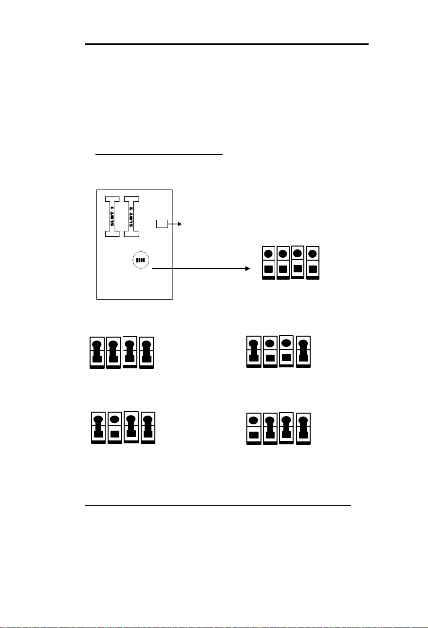
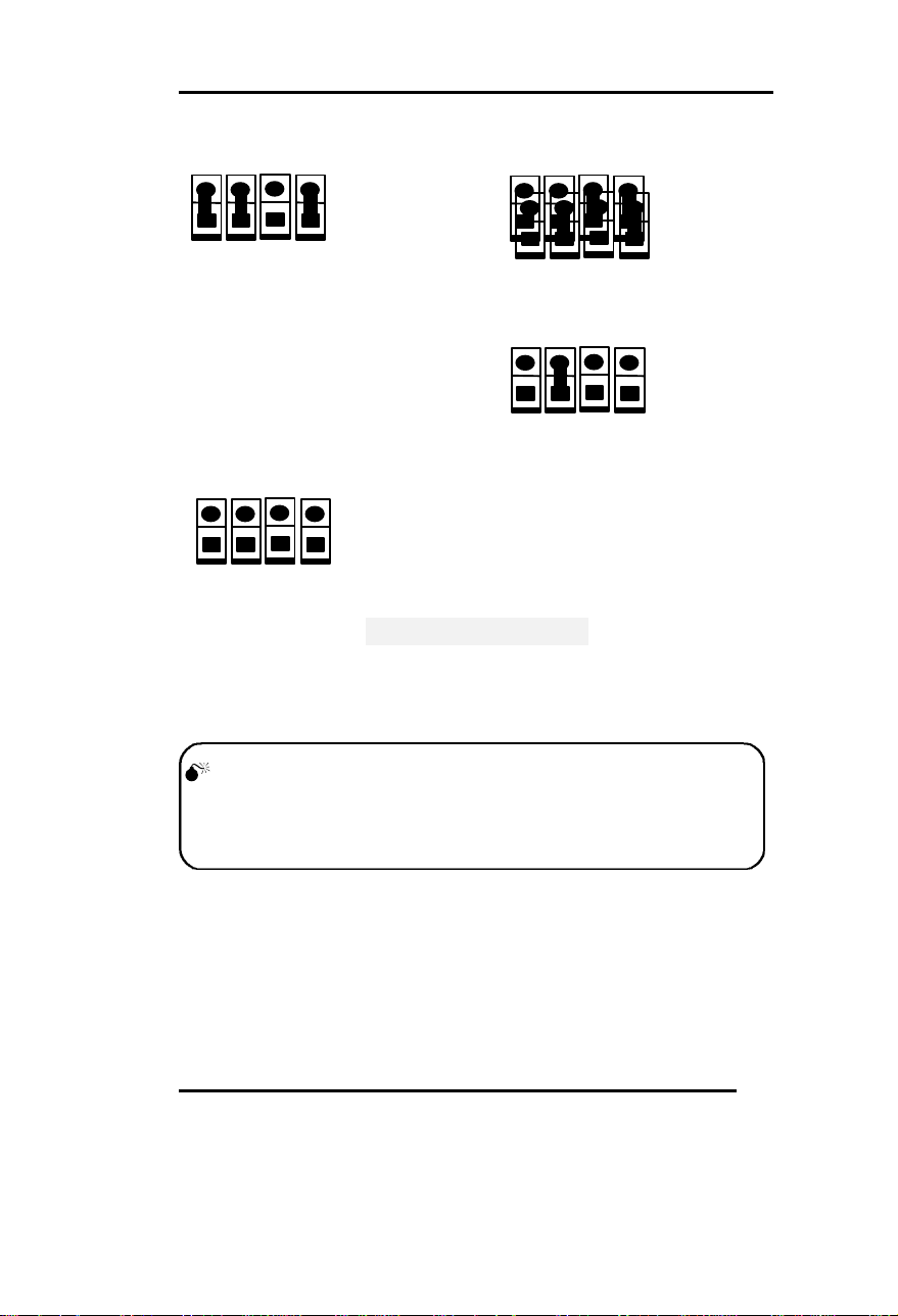
CPU Frequency Selection...........................................................2-1
Clear CMOS...............................................................................2-3
Memory Configuration...............................................................2-3
Wide SCSI Selection...................................................................2-4
SCSI Terminator Control...........................................................2-4
Chapter 3Chapter 3 ∼MainBoard ConnectorsMainBoard Connectors
Connectors using header
Power LED & Keyboard Lock Connector...................................3-1
Power Switch Connector ............................................................3-1
Hard Disk LED Connector.........................................................3-2
Speaker Connector .....................................................................3-2
Turbo LED Connector................................................................3-2
Reset Switch ...............................................................................3-2
Hardware Green Connector .......................................................3-2
Infrared Header..........................................................................3-3
Controller Fan Connector..........................................................3-3
Standard Fan Connector............................................................3-3
Chassis Security..........................................................................3-3
I/O Port and Slot
IDE1, IDE2, FLOPPY, PRINTER, UART1,UART2..................3-4
USB1, USB2, Keyboard, PS2 Mouse..........................................3-4
SLOT1, SLOT2, LAN, AGP .......................................................3-4
PCI1, PCI2, PCI3, PCI4.............................................................3-4

Contents
ii
RAIDPORT, ISA1,2,3, DIMM1, 2, 3, 4..................................... 3-5
Narrow SCSI, Wide SCSI, ATX Power.......................................3-5
Chapter 4Chapter 4 ∼Award BAward BIOS DescriptionDescription
EnteringSetup..........................................................................4-1
Load Setup Defaults.................................................................4-2
Standard CMOSSetup..............................................................4-2
BIOS FeaturesSetup................................................................4-5
Chipset FeaturesSetup...........................................................4-7
Power ManagementSetup........................................................4-9
PNP/PCI ConfigurationSetup...............................................4-12
Integrated Peripherals...........................................................4-14
System MonitorSetup...........................................................4-16
Supervisor/User Password.....................................................4-17
IDE HDD Auto Detection........................................................4-18
Power- On Boot.......................................................................4-20
AppendixAppendix.
Appendix∼∼A BIOS Upgrade Diskette...................................A-1
Appendix∼∼B Installation Procedures...................................A-2
Appendix∼∼C PCI Resource....................................................A-5

Chapter 1
1
-1
Chapter 1Chapter 1
IntroductionIntroduction
Overview
P6I440LX/DP Legend IV is a high-performance and powerful dual Pentium II
processor system, which provides on-board LAN for fast Ethernet network at
10/100Mbps, on-board Ultra Wide SCSI at 40MB/sec, RAID and health
system monitor support. Using the PCI/ISA architecture, the system provides a
highly integrated solution for fully compatible PC/AT platform, featuring the
industry standard ATX form factor. Flexible main memory size can be
installed from 8MB to 512MB SDRAM or 1GB EDO DIMM. The system also
offers a wide range of interface to support integrated on-board IDE and on-
board I/O functions. The system provides 3 modes of green function: Doze,
Standby and Suspend.
Main Features
CPU•Supports single/dual Intel Pentium II CPU at 233/266/300/333MHz
•System clock:66.66MHz
•CPU core frequency = system clock x2, x2.5,x3, x3.5, x4, x4.5,
x5
•Two sets of switching regulator supply CPU core voltage
independently, the voltage from 1.8V to 3.5V adjusted
automatically by CPU’s VID
Chipset
•Intel440LX (82443LX, 82371AB, PIIX4)
•NS82307 I/O chip
•Intel 82093AA I/OAPIC,Intel 82557 LAN controller, NS
P83840A PHY
•Adaptec AIC7880 PCI SCSI Controller.

Introduction
1 - 2
System memory
•Four 168 pin DIMM sockets, capacity of 8MB to 512MB SDRAM or
1G EDO space, 3.3V power supply
•Support memory EC (Error Checking) and ECC (Error Checking and
Correction) function
BIOS
•Licensed advanced AWARD BIOS, supports Flash ROM BIOS, plug
and play ready
On-board I/O
•Support 2 Fast IDE interfaces for up to 4 IDE devices including IDE
hard disks and CD-ROMs
•Support “Ultra DMA/33” Synchronous DMA mode transfers up to 33
Mbytes
•Two high speed serial ports(16550 Fast UART compatible)
•One floppy port supports up to 2 floppy drivers
(360K/720K1.2M/1.44M/2.88M)
Expansion slots
•4 PCI bus slots
•3 ISA bus slots
•1 AGP slot
•1 RAID port
On-board SCSI
•Adaptec AIC-7880 PCI to SCSI controller which is equivalent to
Adaptec AHA_2940UW PCI SCSI Controller.
•Both Ultra wide, narrow SCSI interface
•Data transfer rate up to 40MB/Sec
•Driver for Netware, Windows NT, OS/2, SCO Unix, Unixware. With 1
RAID port, RAID function(RAID 0,1, 0/1 and 5) is supported

Chapter 1
1
-3
•SCSI terminator can be powered up/down automatically or by manual
setting
On-board LAN
•Intel 10/100Mbps PCI to LAN controller 82557, NS DP83840A
and DP83223V physical layer.
•Auto-negotiation
Green function
•Advanced Configuration and Power Interface (ACPI) specification
and OS Directed Power Management
•Supports three green modes: (Doze, Standby and Suspend)
•Power LED will blink when the system is in green status
Advanced Features
•Health system (monitoring the system’s voltages, processor’s
temperature, chassis intrusion and Fan speed by LM78 and
LM75)
•Supports LDSM (LAN Desk Server Manager) software (Optional)
•Supports Windows 95 Software Power-Down
•Supports External Modem Ring Power-On
•Supports Auto Fan-Off when system entering suspend mode
•On-board two USB connectors
•On-board PS/2 mouse and PS/2 keyboard sockets
•All I/O ports can be enabled/disabled by BIOS setup
•Provides Anti-virus function
•Provides Infrared interface
•Green mode
•Supports IDE CD-ROM or SCSI bootup
Board size
•305 mm x 310mm

Introduction
1 - 4
--This page is intentionally left blank--

Chapter 2
2
-1
Chapter 2
System Setting by Jumper
The mainboard offers a set of jumper settings to facilitate clock frequency
adjustment and some important selections.
CPU Frequency Selection
According to CPU’s specification, set CPUs clock speed carefully. The
following illustration lists the jumper settings for the PentiumII CPUs:
JP2 JP3 JP4 JP5
PentiumII 133MHz =2x66MHz
PentiumII 200MHz =3x66.66MHz
PentiumII 333MHZ=5x66MHZ
PentiumII 166=2.5x66MHZ
Speed Table
JP2 JP3 JP4 JP5
JP2 JP3 JP4 JP5JP2 JP3 JP4 JP5
JP2 JP3 JP4 JP5
JP2 JP3 JP4 JP5

System Setting by the jumpers
2-2
PentiumII 266MHz =4x66MHZ:PentiumII 233=3.5x66MHZ
PentiumII 299MHz =4.5x66MHz
PentiumII 133MHz =2x66MHZ:
Remark: All other
Warning::
Set CPU’s clock speed according to its specification.
CPU over speed will be dangerous!
JP2 JP3 JP4 JP5
JP2 JP3 JP4 JP5 JP2 JP3 JP4 JP5
JP2 JP3 JP4 JP5
PentiumII 100=1.5x66MHZ
Combinations
Reserved.

Chapter 2
2 - 3
Clear CMOS Close Once
Normal
Clear CMOS
Note: You must shut down the power
supply first when you
want to clear the CMOS.
Memory Configuration
The P6I440LX/DP Legend IV mainboard supports up to four 168PIN 3.3V un-
buffered DIMM, provides a flexible size from 8MB up to 512MB SDRAM
memory or from 8MB up to 1GB EDO memory. The following set of rules
allows for optimum configurations.
Rules for populating a 440LX/DP Legend IV memory array:
DIMM sockets can be populated in any order. However, to take advantage of
potentially faster MA timing it is recommended to populate sockets in order.
SDRAM and EDO DIMMs can be mixed within the memory array.
The DRAM Timing register, which provides the DRAM speed grade
control for the entire memory array, must be programmed to use the
timings of the slowest DRAMs installed (Please refer to "Chipset
Features Setup" of BIOS).
Possible EDO DIMM memory size is 8MB, 16MB, 32MB, 64MB,
128MB, 256MB in each DIMM socket.
Possible SDRAM memory size is 8MB, 16MB, 32MB, 64MB, 128MB,
256MB in each DIMM socket.
Wide SCSI Selection
JP25 decides the on-board SCSI controller
whether to work in ultra wide SCSI mode or
ultra narrow SCSI mode. Please see the table
listed below.
JP15

System Setting by the jumpers
2 - 4
Wide
Device Narrow
Device
present absent Wide The mode is decided
absent present Narrow automatically by the
present present Wide SCSI Device installed
absent absent Narrow or not.
2-3 Close ignore ignore wide Force into wide mode
1-2 Close Reserved
SCSI Terminator Control
JP34 High byte terminator Low byte terminator
All Open Power-down Power-down
2-3 Close
Power-up if wide mode
selected;
Power-down if narrow mode
selected.
Power-up if only one type of
wide or narrow SCSI device
present;
Power-down if both type
present.
1-2 Close Reserved
JP25 Comment
Mode
All Open
JP34 decides the on-board SCSI
terminator to be power-down or power-up.
The terminator are divided into high byte
and low byte. Please see the table listed
below.

Chapter 3
3 - 1
Chapter 3Chapter 3
MainBoard ConnectorsMainBoard Connectors
This section lists all connector pin assignment and port description on the
main-board. The situations of the connectors and ports are illustrated in the
following figures. Before inserting these connectors, please pay attention to
the directions.
Connectors with HeaderConnectors with Header
Power LED & Keyboard Lock Connector (KEYLOCK)
PIN NUMBER FUNCTION
1LED Anode
2NC
3LED Cathode
4K.B. LOCK
5GND
The LED will blink when system in green status.
Power Switch (POWER)
1. If you want to power up your system, push the button once which connected
to JP16.
2. If you want to power off your system, just push once*again the button.
*Note:If you change “soft-off by PWR-BTTN” from default “Instant-off” to “Delay
4 Secs” in BIOS Setting, you will have to press the power button for more than
4 seconds before the system power down. For details, please refer to Page 4-9.
Hard Disk LED Connector(HD.LED)
1 2 3 4 5
J30
POWER
(JP16)

MainBoard Connector
3 - 2
PIN NUMBER
FUNCTION
1LED ANODE
2LED CATHODE
Hard disk LED indicator should be connected
to the LED of the front-panel.
Speaker Connector(SPEAKER)
PIN NUMBER
FUNCTION
1SPEAKER-
2NC
3GND
4SPEAKER+
Turbo LED Connector (TB. LED)
PIN NUMBER
FUNCTION
1LED ANODE
2LED CATHODE
Reset Switch (RESET)
SETTING
FUNCTION
CLOSE Reset the system
OPEN NORMAL
Hardware Green Connector (SLEEP)
SETTING
FUNCTION
CLOSE Hardware green
OPEN NORMAL
Infrared Header(IR1)
PIN NUMBER
FUNCTION
1 2
1 2 3 4
1 2
JP26
J31
J29
RESET (JP29)
SLEEP (JP31)

Chapter 3
3 - 3
1VCC
2NC
3IRRX
4GND
5IRTX
6VCC
Controlled Fan Connector(FAN2, FAN3, FAN4)
PIN NUMBER
FUNCTION
+FAN+
FAN
SSpeed
SPEED
Note1: FAN4 for CPU1 installed in SLOT1.
FAN3 for CPU2 installed in SLOT2.
FAN2 for other FAN.
Note2: Fan’s current should not be more
than 150 mA for FAN3 and FAN4,
and not be more than 300mA for FAN2
in +12V supply condition.
Standard Fan Connector (FAN1)
PIN NUMBER
FUNCTION
-GND
++12V
NC NC
Chassis Security (JP32):
Connected to the chassis’s Open/Close detecting switch. JP32 Close
means the chassis is close, while Open means it is open.
I/O Port and SLOT DescriptionI/O Port and SLOT Description
(See Figure 3-01)(See Figure 3-01)
1 2 3 4 5 6
-
+
S
-
+
S
NC
+
-
IR1
FAN2FAN2
FAN4 FAN3
FAN2 &
FAN4
- + S- + S
FAN3
FAN1
JP32
DIMM

MainBoard Connector
3 - 4
CONNECTOR FUNCTION
IDE1 Primary IDE Port
IDE2 Secondary IDE Port
FLOPPY Floppy Drive Port
PRINTER Parallel Port
UART1 COM1/COM2/COM3/COM4
UART2 COM2/COM3/COM4/COM1
USB1 First USB Port
USB2 Second USB Port
Keyboard For PS2 Keyboard
PS2 Mouse For PS2 Mouse
SLOT1, SLOT2 Slots for CPU1 and CPU2. When single CPU is needed,
you can select any one of the two slots to install the CPU,
while another slot is for GTC (GTL Terminator Card). It's
necessary to install GTC when single CPU mode is
selected.
LAN On-board LAN I/O Connector. The on-board LAN adapter
occupies PIRQB of the PCI interrupter.
AGP For AGP cards. Since the on-board LAN occupies PIRQB
of PCI interrupter, you must select PIRQA for AGP Card
to avoid the resource’s conflicting.
PCI1 A PCI slave device can be installed, such as VGA card
which does not need interrupter. A PCI master device also
can be installed which needs PCI interrupter, such as a
LAN adapter. If a master device is installed, PIRQA must
be selected and there's no AGP card available.
PCI2 For those PCI slave devices which do not need PCI
interrupter.
PCI3 For those PCI slave devices which do not need PCI
interrupter.
PCI4 It's the same as PCI1 except the PCI interrupter should be
set to PIRQD when a master device is installed. In most
cases, PCI4 combining with the RAID port slot is used for
RAID port card (See RAID port).
RAID port Turn this SCSI embedded Motherboard to be hardware
assist RAID ready by adding the Adaptec ARO-1130

Chapter 3
3 - 5
adapter.
This RAID port option by adding the Adaptec ARO-1130
adapter can support:
Bus Master DMA
Up to 133 Mbyte/Sec Burst rate
RAID 5, 1, 0 and 0/1
Fully Netware 3.11, 3.12, 4.x & WinNT
3.51/4.0 supported by Adaptec
ISA 1, 2, 3 General using for ISA cards.
DIMM 1-2, 3, 4 Memory for SDRAM or EDO.
Narrow SCSI For ultra narrow SCSI peripherals. Be sure the red side of
the cable should align to the end of the connector which is
signed with " ".
Wide SCSI For ultra wide SCSI peripherals.
Note1:Ultra narrow SCSI peripherals and ultra wide SCSI
peripherals can be used at the same time.
Note2:You must assign a different SCSI ID to each device
on the SCSI bus connected to the system board. See your
SCSI device documentation for directions on how to
determine the ID and change it.
Ultra Wide SCSI devices connected to this mainboard’s
SCSI connector can be assigned ID from 0 to 15 (for 68
pin Wide SCSI connection). Normally, ID7 will be used
by the on-board host.
The SCSI ID0 is the best one for SCSI hard disk to be
used as your computer’s boot device; ID1 is best reserved
for a secondary SCSI hard disk. (Only when you use the
SCSI hard disks and devices.)
ATX Power ATX power supply connector.

MainBoard Connector
3 - 6
Figure 3-01 Illustration I/O and slots on board

Chapter 4
4 - 1
Chapter 4Chapter 4
AWARD BIOS DescriptionAWARD BIOS Description
Entering Setup
Power on the computer, when the following message appears briefly at
the bottom of the screen during the POST (Power On Self Test), press
<Del> key or simultaneously press <Ctrl> + <Alt> + <Esc> keys.
Press <Del> to enter SETUP
Once you enter Award BIOS CMOS Setup Utility, the Main Menu
(Figure 1) will be appeared on the screen. The main menu allows you to
select from twelve setup functions and two exit choices. Use arrow keys
to select among the items and press <Enter> to accept or enter the sub-
menu.
ROM PCI/ISA BIOS (2A69JQ19)
CMOS SETUP UTILITY
AWARD SOFTWARE, INC.
STANDARD CMOS SETUP INTEGRATED PERIPHERALS
BIOS FEATURES SETUP SYSTEM MONITOR
CHIPSET FEATURES SETUP SUPERVISOR PASSWORD
POWER MANAGEMENT SETUP USER PASSWORD
PNP/PCI CONFIGURATION IDE HDD AUTO DETECTION
LOAD BIOS DEFAULTS SAVE & EXIT SETUP
LOAD SETUP DEFAULTS EXIT WITHOUT SAVING
Esc :Quit ↑↓→←:Select Item
F10 :Save & Exit Setup ( Shift) F2 :Change Color
Time, Date, Hard Disk Type ...
Figure-1 Main Menu

AWARD BIOS Description
4 - 2
Load Setup Defaults
The Setup Defaults is common and efficient setting.
Standard CMOS Setup
Use the arrow keys to highlight the item, then use the < PgUp> or <PgDn>
keys to select the value you want in each item.
ROM PCI/ISA BIOS (2A69JQ19)
STANDARD CMOS SETUP
AWARD SOFTWARE, INC.
Date (mm:dd:yy) : Fri, Jun 20 1997
Time (hh:mm:ss) :10:10:10
HARD DISKS TYPE SIZE CYLS HEAD PRECOMP LANDZ SECTOR MODE
Primary Master :Auto 000000AUTO
Primary Slave :Auto 0 0 0 0 0 0 AUTO
Secondary Master: Auto 0 00 0 0 0 AUTO
Secondary Slave :Auto 0 0 0 0 0 0 AUTO
Drive A :1.44M, 3.5in
Drive B :None Base Memory :640K
Extended Memory :15360K
Video :EGA/VGA Other Memory :384K
Halt On :All Errors Total Memory :16384K
ESC :Quit ↑↓→←:Select Item PU/PD/+/- :Modify
F1 :Help (Shift)F2 :Change Color
Figure-2 Standard CMOS Setup Menu
Hard Disk
Primary Master/Primary Slave/Secondary Master/Secondary Slave
The categories identify the types of 2 IDE channels that have been installed in
the computer. There are 45 predefined types and 4 user definable types are
used for Enhanced IDE BIOS. Type 1 to Type 45 are predefined. Type “User” is
This manual suits for next models
1
Table of contents
Other QDI Motherboard manuals

QDI
QDI PlatiniX 2D User manual

QDI
QDI Superb 3L User manual

QDI
QDI P6I440EX/MATX EXCELLENT II User manual

QDI
QDI Legend-III P6I440LX/AV User manual

QDI
QDI K8VM800 User manual

QDI
QDI K7VM400M Pro Series User manual

QDI
QDI WinneX 3 User manual

QDI
QDI K8V800 User manual

QDI
QDI GeniuX 1 User manual

QDI
QDI Pentium P5I430TX/IIB TITANIUM IIB User manual