Rabe Aquila User manual

Operating instructions
Mulch seed drill
Aquila
Order no. 9900.01.34GB01

2
We reserve the right to make technical changes.
Read and follow the safety instructions!

3
Read carefully through these operating instructions and safety precautions (“For your safety”) before operating
the implement for the first time, and ensure that they are observed at all times.
The person operating the machine must be trained and qualified in the operation, maintenance and safe use
of the machine, and made fully aware of the hazards involved. Ensure that a copy of the safety precautions is
passed on to all subsequent users.
Ensure that all relevant local accident-prevention regulations are observed, along with generally accepted safety
procedures and any legislation that may apply with respect to health and safety in the workplace.
Observe all warning notices. (DIN 4844-W9)
Instructions in this manual accompanied by this symbol are used to indicate
danger, along with warning notices fixed to the implement.
(See the appendix for details of warning signs.)
The CAUTION symbol indicates safety precautions that must be observed to
prevent danger to the machine or its functions.
The NOTE symbol indicates specific procedures that must be observed to
ensure the smooth and trouble-free operation of the machine.
Loss of warranty
The mulch seed drill is designed exclusively for normal agricultural use. Any use for a purpose other than this
shall be regarded as incorrect operation, and no liability will be accepted for the resulting loss or damage.
The definition of “use for intended purpose” also covers observance of the specified operating, maintenance and
servicing instructions, along with the exclusive use of original spare parts. The use of non-original accessories,
spares and/or consumables that do not carry specific approval from Rabe shall void all warranty liabilities.
We can accept no liability whatsoever for damage, loss or injury resulting from the carrying out of unauthorised
repairs and/or modifications to the implement, or from the inadequate monitoring of its operation.
Claims for missing or damaged items detected at the moment of delivery (transit damage, missing parts) should
be made immediately and in writing.
Warranty claims and our liability exclusions are based on our general terms and conditions.
Mulch seed drill
Aquila
Operating instructions
04.2003

4
We reserve the right to make technical changes.
5
6-7
8
9
9
9
9
9
9
9
9
9
9
10
10
10
10
10
11
11
11
11
12
13
13
14
15
16
17
17
18
19
20
21
List of contents
Brief description
Machine data
Safety precautions
1. Towing
1.1 Coupling the implement
1.2 Brakes
1.3 Electrical connections
1.4 Hydraulic connections
2. Transport position
2.1 The implement
2.2 Folding in the sowing rail and soil
preparation tools / rollers
2.3 Safety
3.Parking the implement
3.1 Uncoupling the brakes
3.2 Hydraulic connections
3.3 Electrical connections
4. Changing to working position
5. Use and adjustment
5.1 Previous soil tillage
5.1.1 Mulching-disc assembly
5.2 Sowing rail
5.2.1 Adjustment of sowing depth / pressure roller
5.3 Lane marker
5.4 Radar system
5.5 Power supply
5.6 Fan speeds
5.7 Recommended dosage settings for Rabe pneum. drilling
machine with hydraulic blower drive
6. Distributor head/tramline
7. Checking of sowing accuracy on drilling machines with
elec. dosing wheel drive.
7.1 Tips for correct usage
8. Maintenance instructions
8.1 Fuses
9. Caution / transport
10. Arrangement of warning signs on the implement
Explanation of warning notices
For your safety

5
We reserve the right to make technical changes.
5.1
Brief description
Aquila - the trailer drilling machine for mulch
sowing and mulching/direct sowing. This compact
version of the machine combines extra-lightweight
frame construction with a carefully-balanced centre
of gravity. The operating widths are 3 m, 4.50 m
or 6 m. With its MegaDrill, Ceria, MegaSeed and
Aquila units, Rabe now offers a new range of seed-
drill machines designed to cover the needs of both
conventional seeding and mulch sowing.
The front of the Aquila is fitted with a Field Bird
two-row disc mulcher (5.1/1). The tyre-mounted
packing roller (5.1/2) (Ø 780x264) running behind
it covers the entire operating width of the machine.
This ensures that the sowing coulters (5.1/3) have
a smoothly-levelled and firm surface to sow on.
A hydraulic system lowers an integrated twin-tyre
running mechanism for the packing roller to allow
transport by road.
The mulch-sowing coulters are a particularly
reliable combination of tilling coulter (5.1/4) and
trailing coulter with 12.5 cm line clearance. Maxi-
mum coulter pressure is 80 kg. A wide, trailing
pressure roller (5.1/5) with soft rubber tyres reliably
guides each of the two coulters to the required
depth in a parallelogram pattern. This machine
makes running speeds of about 15 km/h with
consistently high operating accuracy a practical
possibility.
The centrally-located seed hopper has a volume of
approx. 3000 litres. The large opening (2.50 long)
with hinged flap and wide loading platform ensure
easy filling from a front-loader shovel, worm feed
or Big Bag.
The Artemis electronic module controls the dosing
system and tramline settings, while monitoring all
important machine functions.
1 2 34 5

6
We reserve the right to make technical changes.
Machine data
Dimensions and weights of basic version.
Aquila
Basic type Aquila 4,5m Aquila 6m
Dry weight in kg (approx.) 5600 6800
Tractor from KW/PS 103/140 147/200
Working width D in mm
(approx.) 4500 6000
Lengths A in mm (approx.) 6870
Transport width B in mm
(approx.) 3000
Transport height C in mm
(approx.) 2880 3640
Max. supported load 1500
Max. overall weight 6200 6600
B
C
A
D

7
We reserve the right to make technical changes.
Machine data
Increased noise level perceived by tractor driver (during operation) < “70 dB(A)”.
Aquila hose connections
Aquila
Basic type Aquila 4,5m Aquila 6m
Seed hopper capacity 3000L
Number or rows (space bet-
ween rows 125 mm) 36 48
Tyres 10.0/75-15.3 10PR BKT - AS
Brake system Compressed-air braking system
Seed distribution Pneumatic
Dosing, drive Electronically-controlled electric motor
Fan blower, drive Paddle-blade fan with hydraulic motor
Towing Lower arms cat III, short or twin-axle counterweight
pendant Ø 41
Required hydraulic connec-
tions
2x twin-action, 1x single-action, 1x non-pressurized
return conduit
Hydraulic pressure max. 200 bar
Control / monitoring Electronic
Operating speed up to 15 km/h
Transport speed
25 or 40 km/h*
* depending on operating permit
65432150/ -,+2*),+('0'0
&'%3$)' #*5,"! ,"3254
2+*'*"
(0"32'0*'*"'5/'
-5*20*'('*
31(0/..4*0.,53(2(0
'3(2/'..5(3)
20.*'))5*'.!.*'5*0
5*%(0'.*'))(0!.*'5*
21.0.,53'*.%2*
(0.10,*2/'.1'.32.*2'
*20)*.+''3)
,+2*(.1'.*20)*
*2,".2*"'*)
*2'5*)

8
We reserve the right to make technical changes.
Safety precautions
Do not allow anyone to stand between the tractor and the imple-
ment during coupling or uncoupling, even if this is to allow opera-
tion of the external hydraulic controls. Danger of injury!
Always set the tractor’s hydraulic control mechanism to “attitude
control” before coupling or uncoupling.
Check the tractor and implement before each startup to ensure
that they are in perfect working order for driving and operation.
Observe the maximum axle loads (with full hopper) and maximum
permitted total weight.
Ensure that all safety devices are present and fitted before the
machine is transported.
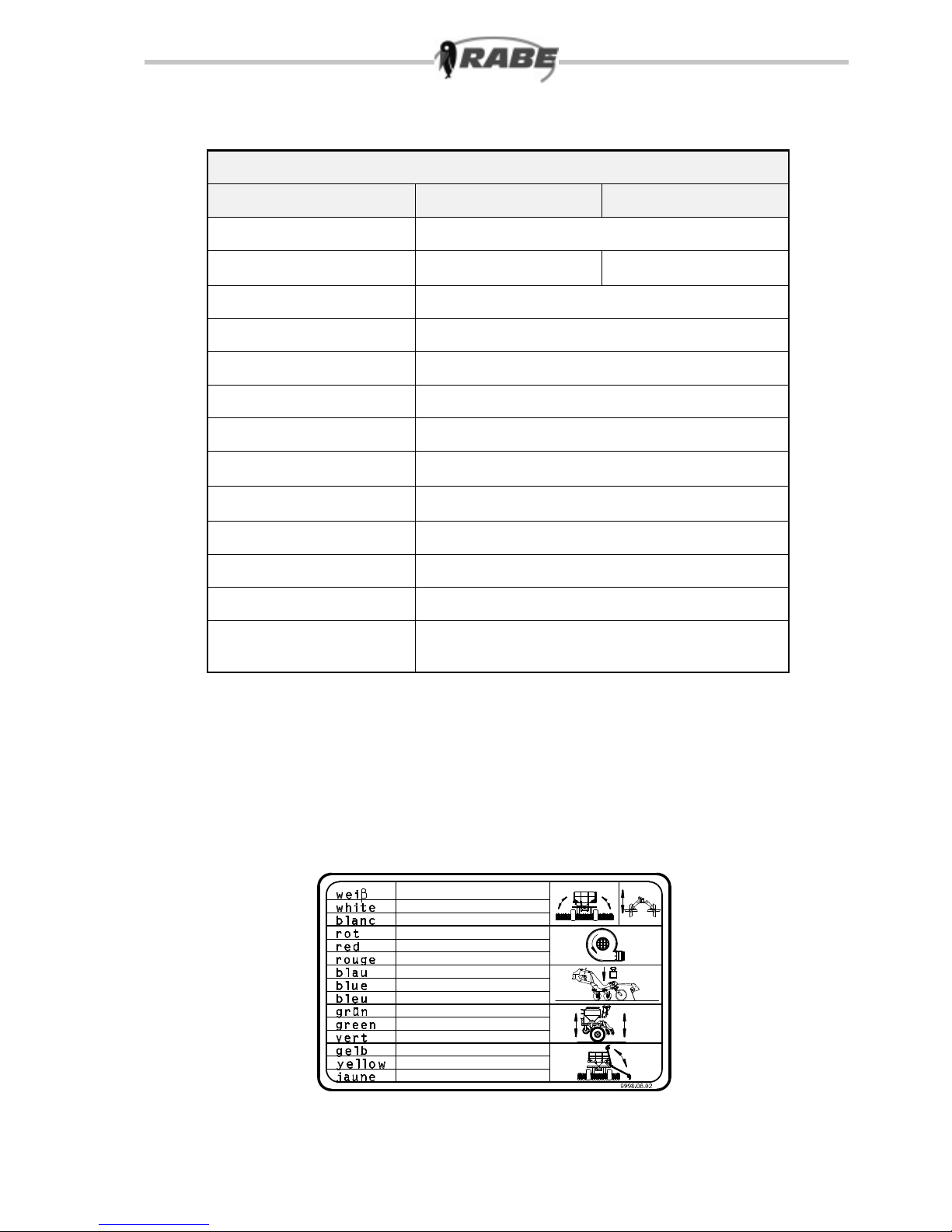
Clear the working and turning area of bystanders before mano-
euvring or operating the implement. (This also applies to the lane
markers.)
DO NOT stand or ride on the implement or remain within its tur-
ning circle or operating area.
Before leaving the tractor unattended, and also before carrying
out adjustments, lower the implement, switch off the engine and
remove the ignition key.
Note that there is a danger of crushing and cutting injuries occur-
ring in the area of the three-point attachment and the hydraulic
lifting and folding mechanism, and during lane marker operation.
Beware of after-running coulters and rollers when the implement
is lifted at the end of a fast run; do not approach until the coulters
and/or rollers have come to a complete stop.
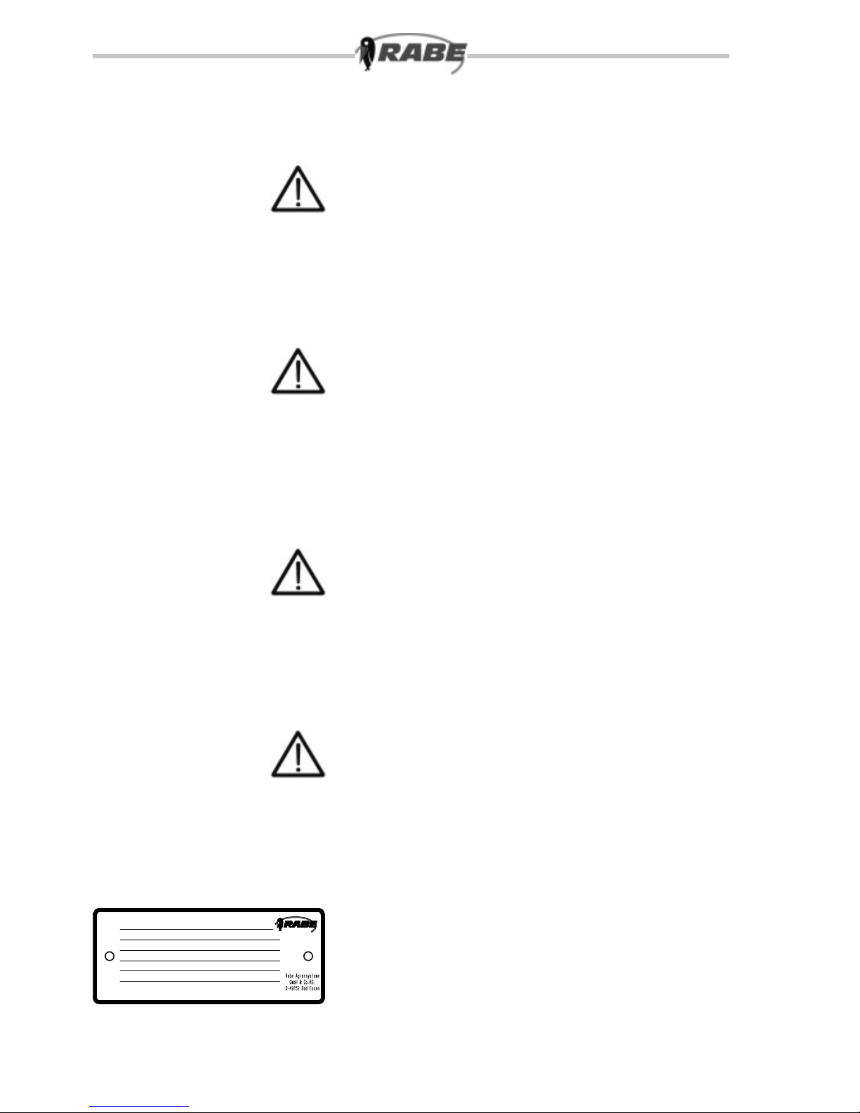
Handle hydraulic components and conduits with care, as they
become hot during operation.
If the blower begins to rattle or vibrate, shut down the hydraulic
system immediately and check the blade wheel of the blower for
correct dynamic balancing.
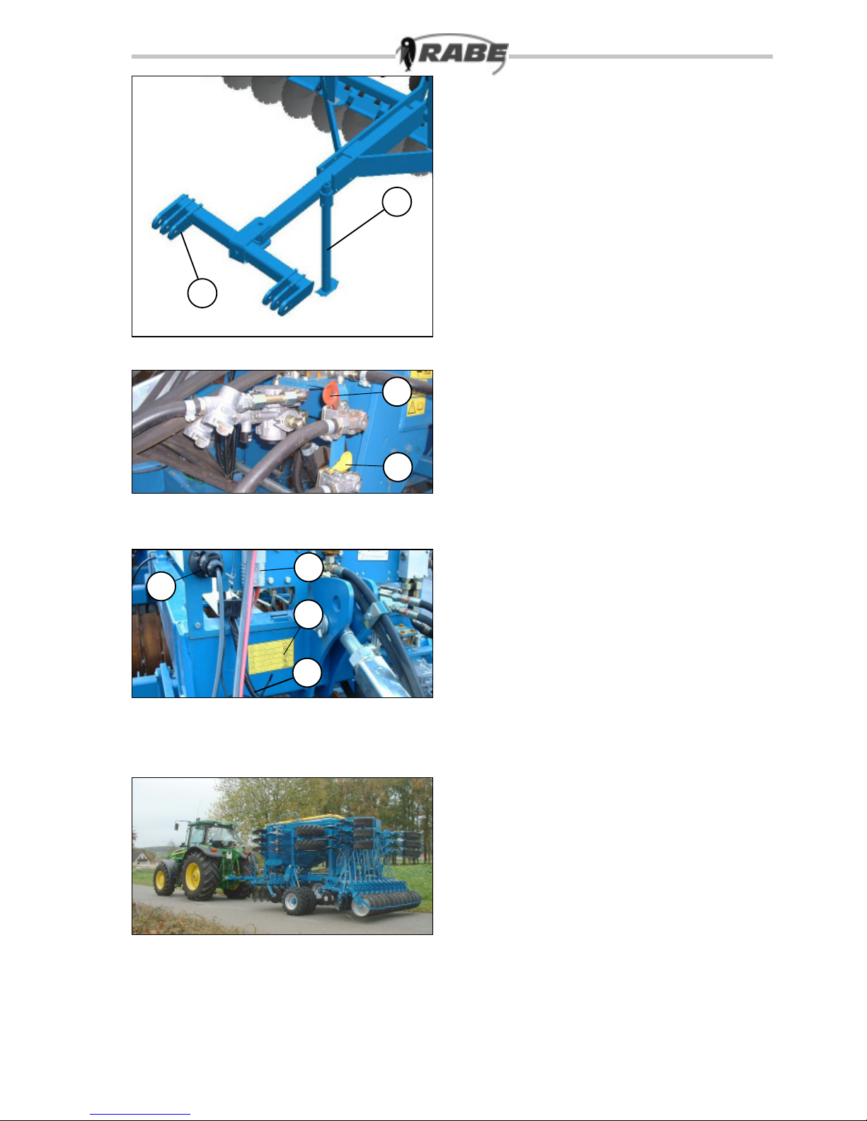
Note that incorrect balancing is dangerous, and can result in irre-
parable damage to the blower. Before carrying out maintenance
or adjustment work on the dosing devices – or driving on public
roads – switch off the electronic system (position “0”) and discon-
nect the system from the power supply (by pulling out the plug-in
connection for the power supply/implement cable loom).
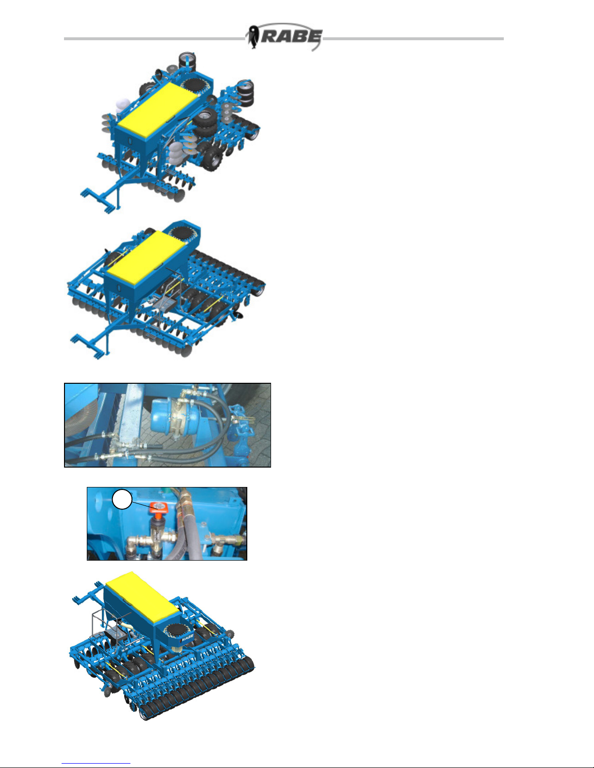
Disable the tractor’s hydraulic control system to prevent accidental
operation while the implement is being towed along public roads.
Always lower the implement at both front and back BEFORE car-
rying out adjustment or any other work.
When filling with treated seed and cleaning the machine with com-
pressed air, note that seed dressing agent is a toxic irritant. Keep
sensitive body parts well protected (e.g. goggles, face mask and
gloves).
Before operating for the first time – or after a long period out of
use – check all screws and bolts for tightness, make sure that all
bearings are sufficiently greased, examine the hydraulic system
for leaks and check tyre pressures.
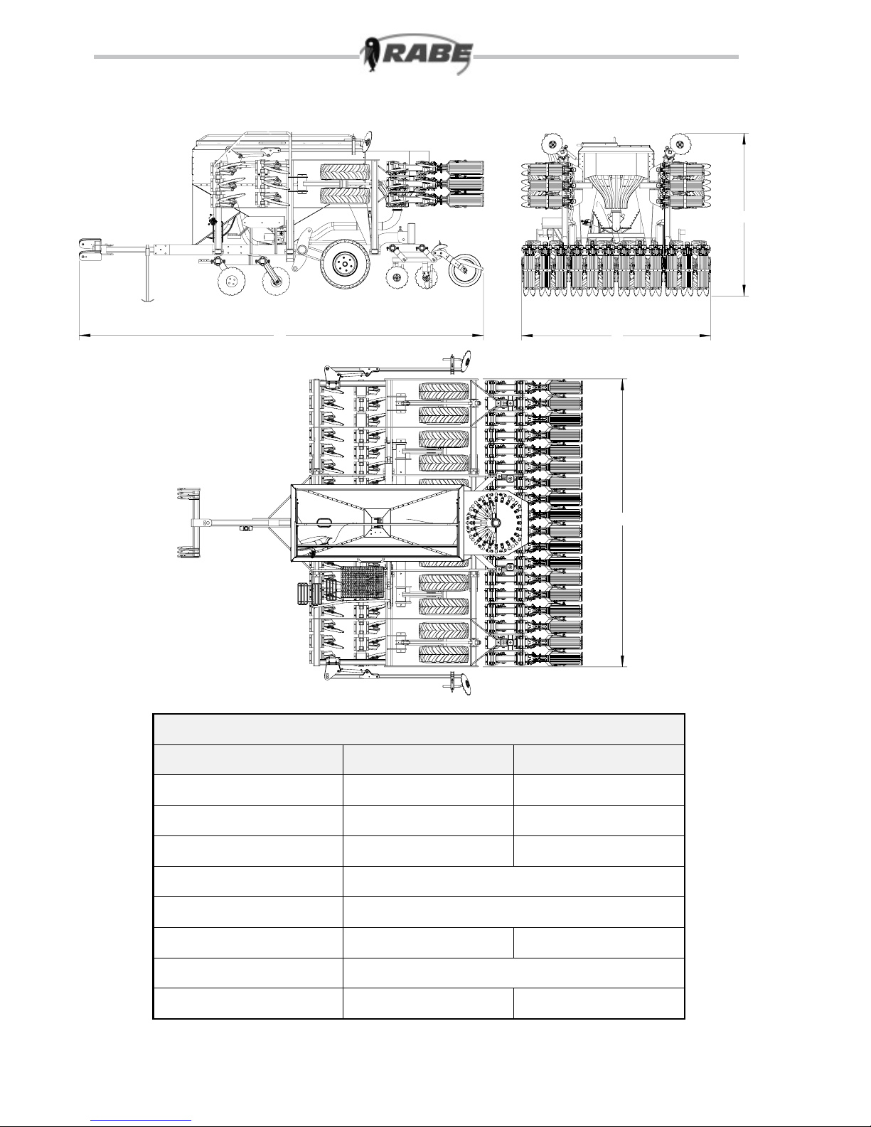
- Maximum length of combination (tractor + implement) 18 m
- Maximum width 3 m
- Maximum height 4 m
- Maximum total weight of combination 16t, of which 20% on front
axle.
The operating pressure of the hydraulic system must not exceed
200 bar.
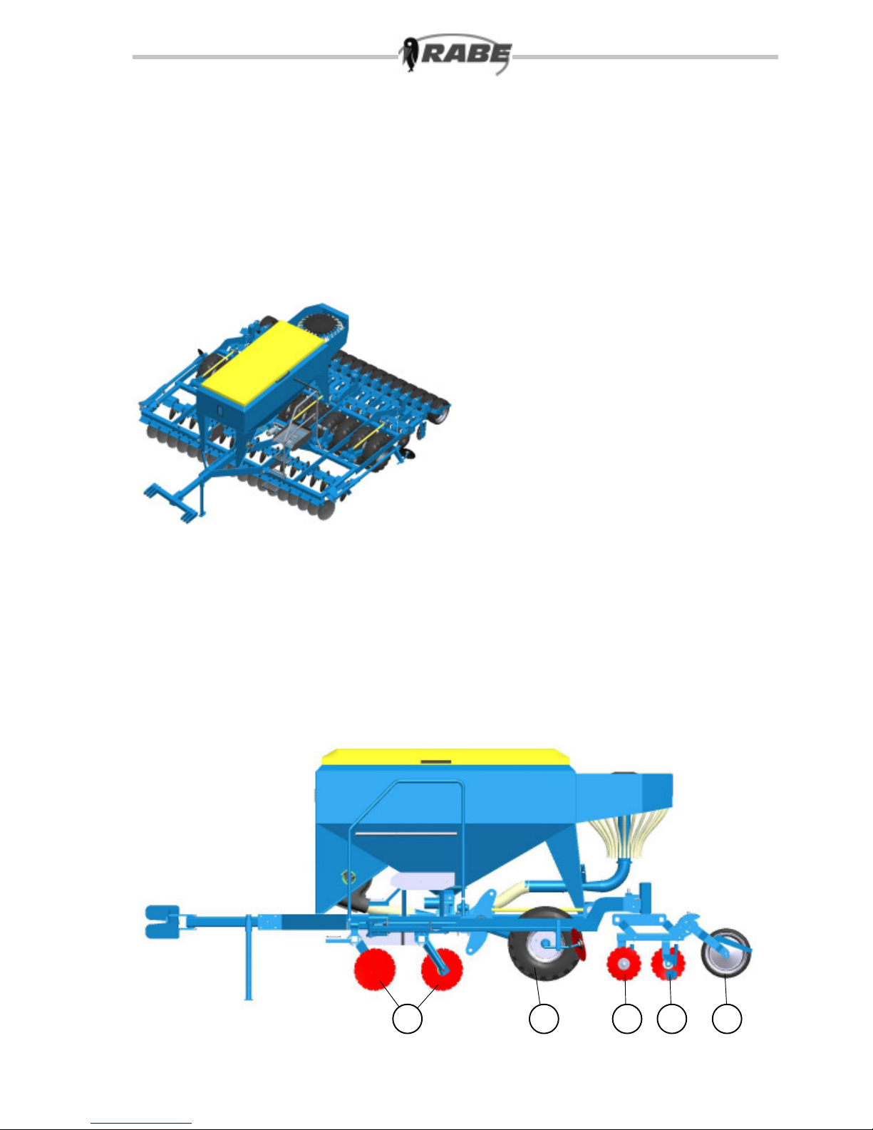
The machine identification plate (8.1) contains certification details,
and must not be altered or made illegible.
8.1
Fz.-Ident.-Nr.
zul. Stuetzlast
kg
kg
kg
kg
zul. Gesamtgewicht
Typ:
Baujahr: Nr.
zul. Achslast
Eigengewicht

9
We reserve the right to make technical changes.
1. Towing
1.1 Coupling the implement
Couple the lower-arm floating axle (9.1/1). Cor-
rectly secure the coupling assembly.
Secure the tractor’s lower arm in the centre.
Retract the support stands (9.1/2).
1.2 Brakes
Connect the yellow brake line (9.2/2). Connect the
red brake line (9.2/1).
The spring-loaded brake is released as pressure
builds up in the braking system.
1.3 Electrical connections
There are three electrical connection points at the
front of the machine:
- Power lead (9.3/1) for the electrical dosing-
mechanism drive.
- Control lead (9.3/2) to act as connection for the
drill computer.
- Connection lead (9.3/3) for the lighting system on
the trailer drilling machine.
1.4 Hydraulic connections (9.3/4)
Depending on the configuration of the implement,
the following hydraulic connections are required:
- Single-action control device with Ø 22 mm non-
depressurized return conduit for the hydraulic
blower drive
(Plug-in coupling subass. 4).
- Twin-action control device for the running gear.
- The twin-action control device for the lane marker
can be switched over, when required, to alter the
receiver pressure of the hydraulic coulter rail load.
2. Transport position
2.1 The implement
Raise the implement at the back and front so that
the frame is lifted horizontally. (9.4)
2.2 Folding in the sowing rail and soil
preparation tools / roller
Note that the implement must be fully raised for
folding in and out. (9.4)
Fold in the folding parts with the twin-action con-
trol device. The folding half-sections are locked
hydraulically in their retracted position.
Caution: Block the tractor‘s onboard control unit to
prevent accidental operation during transport ope-
rations. Switch off the electronic system and/or pull
out the plug.
2.3 Safety
Before transporting on public roads, ensure that
the safety devices are attached and that the road
lights are in working order.
Observe the transport procedures.
9.1
9.2
9.3
9.4
1
2
1
2
1
3
2
4

10
We reserve the right to make technical changes.
3. Lowering the implement
The implement can be parked in either its retracted
(10.1) or extended position.
We recommend putting the implement in its folded-
out position (10.2) and lowering it completely
before storing it for the winter.
Parking in retracted position (10.2):
Lower the running gear as far as possible.
You should also prop up the implement frame on
both sides to prevent accidental lowering.
Chock the machine to prevent it rolling away.
3.1 Uncoupling the brakes
Uncouple the red brake line and hang it in its
holder (9.2/1);
Uncouple the yellow brake line and hang it in its
holder (9.2/2);
The spring-loaded brakes act on the running gear.
When the pressure vessel is full, pressing the red
button on the brake valve (10.4/1) releases the
brake once (even if the brake line is disconnected).
3.2 Hydraulic connections
Uncouple all hydraulic connections from the tractor.
Protect the hydraulic plug from dirt with the sealing
caps and place in the holder provided for this pur-
pose.
3.3 Electrical connections
Disconnect all cables from the tractor. Store the
removable electronic control box and its cables in
a dry place.
Carefully cover the plug sockets on the implement
and tractor.
4. Changing to working position (10.5)
Extend the folding tools and sowing rails with twin-
action control device.
Fully extend the cylinder. Horizontal position of the
tools.
Switch on the electronic operating system.
10.2
10.3
10.1
1
10.5
10.4

11
We reserve the right to make technical changes.
5. Use and adjustment
5.1 Previous soil tillage
5.1.1 Mulching-disc assembly
The working depth of the disc coulters (11.1/1) is
set by the tyre-mounted roller (11.1/2).
Adapt the drill speed to the nature of the mulching
operation. This also increases sowing perfor-
mance.
5.2 Sowing rail
Coulter pressure adjustment: Coulter pressure is
adjusted to a fixed setting. This is based on the
proportional weight of the machine, as transferred
to the coulters and pressure rollers. The paralle-
logram arrangement of coulter elements can be
directed upwards. The disc coulters are spring-
mounted on rubber elements (11.2/2).
5.2.1 Adjustment of sowing depth /
pressure roller
Start by adjusting the pressure rollers (11.4) to the
required sowing depth with the eccentric me-
chanism (16-position) secured in the gauge hole
(11.2/1). - Adjust all pressure rollers to the same
setting.
...for “normal sowing depth”: on a firm, even sur-
face, set the pressure rollers to the coulter level
(11.3/1). (4th or 5th hole 11.5/1). Sowing depth
may have to be corrected for field operation (by
means of the eccentric mechanism and gauge hole
11.2/1)
2
1
11.2
11.3
1
Deep
Flat
11.4
1
11.5
1
2
11.1

12
We reserve the right to make technical changes.
5.3 Lane marker
The disc lane markers can be centred up with respect
to the tractor. Setting: move the extension arms into
their operating positions. Adjust the disc contact point
(12.1/1) correspondingly; (depending on working width
and row distance of the drilling machine and the tractor-
lane width during lane marking).
The lane marker is switched over by means of a
hydraulic shuttle valve on the drilling machine. A single-
action control valve must be fitted to the tractor for this
purpose.
Fine adjustment is carried out by displacing the mar-
king disc.
Centring-up with respect to tractor (12.2.1), measured
from outer share:
Working width + row distance = A
2
Example: 3 m operating width (B = 300 cm)
12 cm space between rows (R = 12 cm)
170 cm tractor lane (S = 170 cm)
B + R 300 + 12 = 156 cm = A
2 2
Turn the disc axle (12.1/2) to give the disc more or less
grip on heavy or light soil accordingly.
The lane markers are switched over at the forward
furrow by means of a single-action tractor control
device
... Set to “raise” at the end of the traverse – both lane
markers are now raised,
... When starting the “lower” traverse – during operation,
the control device must always be left set to “lower”
(floating setting).
12.2
12.1
1
2
S
A
B
R

13
We reserve the right to make technical changes.
5.4 Radar (13.1/1)
The radar device supplies the control system with
traverse-related data. Tracking detection is carried
out without contact. The dosing system stops if the
fan speed is too low (to prevent blockages).
5.5 Power supply (13.2)
Operating power is taken directly from the tractor
battery. The power-supply cable loom, including
main fuses, master switch (13.2/ 1) and plug sok-
kets, is permanently installed on the tractor.
13.2
1
13.1
1

14
We reserve the right to make technical changes.
5.6 Fan speeds
The corresponding blower speed should be
selected to provide an appropriate stream of
air for the operating width and seed type.
The current fan speed is displayed at the computer
terminal (14.1).
An oil capacity of approx. 30 litres/ min is required for
operation at max. fan speed.
A hydraulic valve (14.2/2) regulates fan speed. For
operation at min. fan speed, the hand wheel (14.2/1)
should be turned outwards until the desired turning
speed is reached.
-turn out = reduced volume (lower turning speed)
-turn in = increased volume (higher turning speed)
For operation at max. fan speed, the hand wheel
should be turned inwards until the desired turning
speed is reached.
The hand wheel should then be locked in place.
Hydraulic blower drive requires the following tractor-
mounted items:
- With open hydr. system, a separate oil circuit with a
min. feed rate of 35 l/min.
- Single-action control device or twin-action control
device with oil quantity adjustment and float setting.
On load-sensing or closed hydr. system, a single- or
double-action control device with priority switching
and oil-flow adjustment. Before initial startup of the
blower, the flow rate should be adjusted at the tractor-
mounted control device to approx. 30 l/min. At redu-
ced blower speeds, the flow rate should be increased.
- Non-pressurized return with NW 22 tube and size-4
hydraulic system.
- Hydraulic-oil cooler to prevent damage to the
tractor’s hydraulic system: If the blower is operated
with a twin-action control device, it must be possible
to switch the control device directly from operating to
fl o at setting at switch-off.
Control device to “lower” = blower op.
Control device to “float setting” = blower switched off.
IMPORTANT !!!
In order to prevent fluctuations in fan speed when
towing with the load-sensing system, all further powe-
red items (coulter-pressure adjustment, lane markers,
etc.) should be adjusted at the corresponding control
device to run with the lowest possible quantity of
oil. For long-term operation of the blower, follow the
indications in the operating manual supplied with the
tractor, or consult with the tractor manufacturer.
Fan speeds
Operating
width
Fan speed
min max
from 4m 2500 3500
Operating
position
Pressure range
Approximate values
from 4m
Coarse
seed 80 - 100 bar
Fine seed 30 - 50 bar
14.1
14.2
1
2

15
We reserve the right to make technical changes.
5.7 Seed wheel settings for pneumatic
seed drills with hydraulic fan drive
X Standard setting
O Use possible
* Use the reduced fan drive setting (R) for seed rates below 20 kg/ha. The kg/ha figures are only
approximate
Fan rpm
Fan setting up to 3m > 3m
Normal (N) 3000 3500
Reduced (R) 2300 2800
I without agitating
fingers
Seed
Variety
Seed wheels
Bottom
flap posi-
tion
Fan
setting
Standard seed wheels Coarse seed
wheel(100%
fi l led)
Order No.
9001.24.30
Coarse seed
wheel (50%
fi l led)
Order No.
9001.24.31
Coarse
seed wheel
engaged
2 small
seed
wheels
engaged
1 small
seed wheel
engaged
Wheat XO O 1 N
Barley XO1 N
Rye XO O 1 N
Triticale XO O 1 N
Oats XO O 1 N
Spelt (Grain) XO1 N
Oil seed rape X I O I(<2,5kg/ha) O I2 R
Foder rape O I X I 2 R
Red clover O I X I 1 R
Lucerne OX1 R
Turnips X I O I1 R
Lupins O I X I 3 N
Mustard O I X I 1 R
Radish O I X I 1 R
Phacelia OX1 R
Vetches XO1 N
Grass seed X (>20 kg/ha) O (<12 kg/ha) O (>10 kg/ha) 1 N/R*
Peas O I X I 4 N
Beans OI X I 4 N
Flax OX1 N
Linseed X1 R
Sunflower O I X I 2 N
Soja O I X I 3 N

16
We reserve the right to make technical changes.
6. Distributor head/tramline
The dosed seed is evenly allocated by the distri-
butor head, and fed to the coulters via the spiral
hoses.
Note that the hoses should slope downward
towards the coulters Sagging hoses should be
made to slope downwards and/or shortened accor-
dingly.
With the tramline function activated, the seed is
“fed back” from the outlets concerned and the
dosing quantity is automatically reduced by this
amount.
At the tramline outlets, the lower flap lever is linked
to the servomotor by a screw-mounted spring
(16.1/1);
“spring length” must be set with the cable clamp so
that the flap lies at the top on the outlet wall with
the tramline activated.
The upper flap lever (16.1/2) (left) on the tramline
outlets MUST NOT be fixed in position.
16.1
Tramline seed return
2
1

17
We reserve the right to make technical changes.
7.1 Tips for correct usage
- Preparing the combined implement for work:
soil preparation tools, running gear, lane mar-
kers, fan speed / hydraulic motor.
- Check settings (as in turning test): Dosing-
wheel setting (coarse-dosing wheel blocked
when using fine seed), agitator shaft (agitator
fingers removed when handling rapeseed),
turning cover, seed-quantity settings,
- Switch on the electronic system.
- When starting up prior to use, run the motor
at half-speed at least, then maintain a constant
turning speed,
- Start sowing operation. Note that seed takes a
certain time to get from the dosing mechanism
to the sowing coulters (approx. 1 s / 2 m). This
should also be taken into account when stop-
ping briefly. Raise the implement and carry out
a reset (see “Pre-dosing”).
- Check all coulters for blockages before star-
ting to sow, and re-examine at regular intervals.
- Check sowing depth
- Match drive speed to working conditions so
that the seed is evenly spread.
- Always leave the hydraulic control device for
the lane markers in “float” mode during opera-
tion (see also “Lane markers”),
- When filling up, ensure that no foreign bodies
(waste paper, sack ties) get into the hopper.
Keep the hopper cover closed during opera-
tion. Monitor the filling level (low-level indica-
tor),
- Given the hygroscopic characteristics of seed
(including dressing agent), the hopper should
be emptied before a long period without opera-
tion. Note that dressing agent is a toxic irritant.
- Emptying the remains: Lower the drilling
machine and place a collection container
under the discharge hopper. After emptying,
turn all dosing wheels slightly (with star grip)
and/or press the button to run the fan briefly to
remove all remains of seed (so as not to attract
rodents and other pests).
7. Checking of sowing accuracy on
drilling machines with elec. dosing
wheel drive.
Rule 1
The electrical turning system and manual
turning system at the tail wheel must always
produce the same turn readings.
(Only slight fluctuations are permitted)
(Only possible on machines with tail wheel)
Rule 2
The electronic Ha counter setting
must match the working width of the
machine.
Rule 3
The turning procedure should only be carried
out without enabling the additional amount.
Rule 4
Select the recommended dosing-wheel setting.
Rule 5
Use calibrated scales (domestic scales). Do
not use a spring balance or sack scales.
The above points must be observed if best-
possible performance is to be guaranteed.

18
We reserve the right to make technical changes.
8. Maintenance instructions
Sensor adjustment: The inductive sensors are set to a
gap of 1-3 mm. To adjust the fan sensor (18.1/1), pro-
ceed as follows: Rotate the fan shaft (18.1/2) so that the
shaft groove is not aligned with the threaded hole of the
sensor. Rotate the sensor by hand up to the fan shaft,
then rotate it back by 3½ turns and lock with the nut. The
sensor is fitted with an LED function indicator so that
“Function of sensor” is displayed whenever a correction
adjustment or test activation takes place.
Use a soft cloth and mild household detergent to remove
any dirt from the drill computer-box (DO NOT use sol-
vents).
DO NOT immerse the housing in liquid.
Disconnect all wires to the electronic terminal box before
carrying out welding work on the tractor or attached
devices, or when charging the tractor battery or connec-
ting a second battery (for carrying out a jump-start).
Given the hygroscopic characteristics of seed (including
dressing agent), the hopper (and dosing wheels) should
be emptied before a long period without operation. Run
the blower briefly to complete the emptying of the seed
conduits. After cleaning, leave the emptying outlet and
rotating cover open, so as not to attract rodents and
other pests. When carrying out cleaning operations,
note that dressing agent is a toxic irritant. Protect such
sensitive parts of the body as the mucous membranes,
eyes and respiratory organs. Do not allow earth or mud
to dry on the coulters. Apply a grease gun to the lubrica-
tion nipples of the bearings at regular intervals (i.e. every
100 hours). A toothed pressure roller will remain in good
condition if it is cleaned after each operation and pro-
tected from corrosion.
Park the Aquila machine in a dry, undercover location,
with its coulters and lane discs clean and protected to
prevent corrosion. Protect the electronic terminal box
(with connection cables) from moisture and store in a dry
place.
Cover the plug socket for the supply cable loom (to
protect from possible soiling). Check the hydraulic hose
conduits at regular intervals and replace any damaged
or brittle items (see list of spare parts). Hose conduits
are subject to a natural ageing process and should be
replaced at intervals of no more than six years. Avoid
directing the hose at the bearings for any length of time,
especially when cleaning the implement with high-pres-
sure water. (The inductive sensors on the monitoring
devices are set to a gap of 1 - 3 mm (18.2). The sensor
is fitted with an LED function indicator so that “Function
of sensor” is displayed whenever a test activation takes
place. For details of sensor adjustment, (see mainte-
nance instructions).
1 - 3mm
18.2
1 - 3 mm
18.1
1
2

19
We reserve the right to make technical changes.
19.1
19.2
8.1 Fuses
Residual risks
Danger zone Note
Folding side sec-
tions Operating instructions
Transport position Operating instructions
Fuse overview
Place of
installation Fuse designation
Rabe arti-
cle no.
Supply cable
loom
(19.1/1)
Flat vehicle-type
fuse
20A
9012.14.34
Switch box
(19.2/1)
Flat vehicle-type
fuse
10 A
9012.14.10
1
1

20
We reserve the right to make technical changes.
9. Caution / transport
Bring device into position for transporting; check for
transport readiness.
Do not carry passengers, and keep away from the
danger area.
The tractor can tow trailer implements weighing up to 3
t in weight; trailers with an axle weight of over 3 t must
be fitted with brakes.
Maximum speed, depending on the type of operating
permit, is 25 km/h or 40 km/h.
Observe the relevant speed limits and traffic regulations
when transporting the implement by road. Always take
the centre of gravity into account.
Observe the corresponding road traffic regulations
(StVZO or local equivalent). These specify that the user
is responsible for the correct hitching of the tractor and
implement for driving on public roads and rights of way.
Attached implements must not affect the safe driving of
the tractor-trailer combination. The attachment of the
implement must not result in the maximum permitted
axle weight of the tractor, the maximum permitted total
weight, or the load capacity of the vehicle tyres (regard-
less of air pressure) being exceeded. For safe steering,
the front axle of the tractor must bear at least 20% of
the vehicle‘s unladen weight.
The maximum permitted width of the load is three
metres. The tractor and trailer must not exceed a total
length of 18 m.
A special permit is normally required if the maximum
permitted dimensions are exceeded.
No avoidably overhanging item must endanger other
traffic or road users (sect. 32 StVZO or your local
equivalent). Overhanging items that cannot be avoided
must be covered and fitted with warning notices. Safety
devices include appropriate lighting and signs around
all sides and the rear of the vehicle and towed imple-
ment, e.g. red/white striped warning signs (423 x 423
mm) and triangles (stripes of 100 mm in width, angled
at 45°, running from outside to bottom).
Towed implements and semi-trailers must be fitted
with rear red revolving flashing lights and lateral amber
flashing revolving lights, and must be driven with the
vehicle lights switched on at all times – even in daytime
(additional warning lights must be fitted if the implement
protrudes by more than 400 mm outside the normal
trailer lights).
RABE can supply, as optional extras, the safety covers
required for transport on public roads.
RABE can also supply the TÜV certificate required for
issue of an operating permit in certain jurisdictions.
When transporting on public roads in Poland, the war-
ning triangle (20.1/1) must be fixed to the centre of the
machine.
1
20.1
Table of contents
Other Rabe Farm Equipment manuals

Rabe
Rabe Packer CR User manual

Rabe
Rabe Digger HA User manual

Rabe
Rabe ADLER DS18 800 User manual

Rabe
Rabe KORMORAN PL V 180 User manual

Rabe
Rabe KORMORAN SF 180 User manual

Rabe
Rabe Pavo V 140 User manual

Rabe
Rabe COMBIBIRD CB User manual

Rabe
Rabe Raven Avant Series User manual

Rabe
Rabe Albatros Variant User manual

Rabe
Rabe Combi-Digger Series User manual
Popular Farm Equipment manuals by other brands

New Holland
New Holland FR480 Forage Cruiser Service manual

Tatu Marchesan
Tatu Marchesan COP 15 user guide

Art's-Way Manufacturing
Art's-Way Manufacturing 660800 Operator's manual

Te Pari
Te Pari EasyDose quick start guide

Heiniger
Heiniger ONE/G Translation of the original instructions

Baroness
Baroness LS62 Owner's operating manual