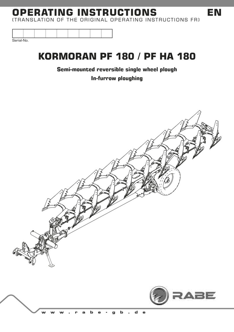
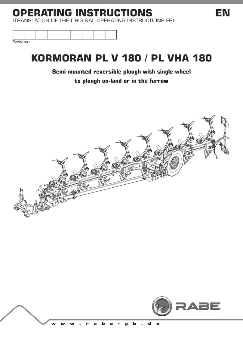
Rabe KORMORAN PL V 180 User manual

ADDENDUMS
OPERATING INSTRUCTIONS EN
(TRANSLATION OF ORIGINAL VERSION DE)
www.rabe-gb.de
KORMORAN PF V 180 / PF V HA 180
Contains important information on start-up.
5HDGEHIRUHWKH¿UVWVWDUWXS
and
EHIRUHWKH¿UVWIROGLQJWRJHWKHU
CONTENT
Addendum to the operating instructions 9901.00.17EN04
SECTION: INTRODUCTION ..................... 3
1 Supplement to Chapter 2 - “Safety instructions
and rules” .................................................. 3
2.1.9 Safety stickers ...........................................................3
SECTION: USE....................................... 3
2 Supplement to Chapter 3 - “Description of the
implement” ................................................. 3
3.5a Technical characteristics - accumulator
3.5L ........................................................ 3
3 Supplement to Chapter 10 - “Field adjustment”
4
10.10a Adjusting the Vari Heavy Duty skimmers.. 4
10.10a.1 Vari Heavy Duty - adjusting the working depth .........4
10.10a.2 Vari Heavy Duty skimmers - lateral overlap...............4
SECTION: MAINTENANCE...................... 5
4 Supplement to Chapter 14 - “Troubleshooting
and repair” ................................................. 5
14.2a Replacing the Vari Heavy Duty (VHD)
shear bolt ............................................... 5
14.5 Adjust undercut ...................................... 6
5 New Chapter 15 - „Replacing wear parts” ..... 9
15.1 Replacing mouldboards ......................... 9
15.2 Replace the stripes ................................ 9
15.3 Replace the tine ..................................... 9
15.4 Replace the tines with reversible points10
15.5 Replace the trash board....................... 10
15.6 Replace the subsoiler .......................... 10
15.7 Replace the skimmer tines and
mouldboard .......................................... 11
15.8 Replace the disc coulter....................... 11

7KLVDGGHQGXPLVRQO\YDOLGLQFRQMXQFWLRQZLWKWKHVSHFL¿HGRSHUDWLQJ
LQVWUXFWLRQV
• Follow the safety instructions of the operating instructions for the basic
machine.
• Before start-up, read and take note of the operating instructions
and addendum.
• Retain for future reference.

- 3 -
Status 2017-02
327
ø175
M22x1.5
M28x1.5
ADDENDUM TO KORMORAN PF V / VHA OPERATING INSTRUCTIONS
6XEMHFWWRWHFKQLFDOPRGL¿FDWLRQV
9901.00.17A-EN04 - 02/2017
SECTION: INTRODUCTION
1 SUPPLEMENT TO CHAPTER 2 - “SAFETY INSTRUCTIONS AND
RULES”
SECTION: USE
2 SUPPLEMENT TO CHAPTER 3 - “DESCRIPTION OF THE
IMPLEMENT”
6DIHW\VWLFNHUV
5HWLJKWHQDOOEROWVVWLFNHU 6WLFNHU 'HVFULSWLRQ
9998.06.40
Re-tighten all bolts every 50 operating hours.
3.5a Technical characteristics - accumulator 3.5L
'HVFULSWLRQ 7HFKQLFDOGDWD
Type E1, rechargeable
Volume 3.5 Litres
Charging pressure 70 bar
Maximum allowable working pressure 210 bar
Gas Nitrogen
:RUNLQJÀXLG Hydraulic oil
Working temperature -10°C to +80°C

- 4 - Status 2017-02
ADDENDUM TO KORMORAN PF V / VHA OPERATING INSTRUCTIONS
Subject to technical modifications 9901.00.17A-EN04 - 02/2017
3 SUPPLEMENT TO CHAPTER 10 - “FIELD ADJUSTMENT”
10.10a Adjusting the Vari Heavy Duty
skimmers
D 9DUL+HDY\'XW\DGMXVWLQJWKHZRUNLQJ
depth
Adjustment instructions
H
a
H = factory setting: approx. 18 cm
ÂThe Vari Heavy Duty working depth is calculated from the gap
to the blade tip (H)
ÂAdjust H so that the cutting edge (a) works in the soil across
the entirety of its width.
ÂEnsure that all skimmers are adjusted evenly.
Adjustment - Vari Heavy Duty skimmers
T
H
0
5
10
15
20
25
30
35
40
cm
cm0 5 10 15 20 25 30 35 40
Pflugkörper Arbeitstiefe T
Vari-Fix Abstand H
Beispiel:
Arbeitstiefe T 22 cm = Vari-Fix Abstand H 16 cm
- Use the diagram to determine gap H.
I
II
1.
4.2.
3.
- 1. Remove the retaining ring.
- 2. Remove the locking pin and ...
- 3. ... adjust working depth by aligning the hole in the rod (I)
with the pawls in the bracket (II).
- 4. Insert the locking pin (2) in the required hole and secure
with the retaining ring.
- Adjust all skimmers to the same working depth.
D 9DUL+HDY\'XW\VNLPPHUVODWHUDORYHUODS
B
The lateral overlap (B) for the Vari Heavy Duty is preset to
between 2 and 3 cm in the factory.

- 5 -
Status 2017-02
ADDENDUM TO KORMORAN PF V / VHA OPERATING INSTRUCTIONS
6XEMHFWWRWHFKQLFDOPRGL¿FDWLRQV
9901.00.17A-EN04 - 02/2017
SECTION: MAINTENANCE
4 SUPPLEMENT TO CHAPTER 14 - “TROUBLESHOOTING AND
REPAIR”
14.2a Replacing the Vari Heavy Duty
(VHD) shear bolt
Attachment
1
2
3
4
/HJHQG
0VKHDUEROW
0VHOIORFNLQJQXW
0SLYRWEROW
0VHOIORFNLQJQXW
Repair instructions
ÂSystematically insert th e shear bolt (3) from the link arm side.
ÂAlways use the original shear bolts.
ÂReplace damaged bolts with OEM bolts.
Repair
1.
2.
- 1. Loosen the nut of the pivot bolt (WAF 24 mm).
- 2. Swing the skimmer into position.
5.
3.
4.
- 3. Insert the new shear bolt from the link arm side.
- 4. Tighten the shear bolt fastening nut (WAF 19 mm).
- 5. Block the shear bolt nut and the pivot bolt nut, observe the
tightening torque.
Tightening torque - shear bolt
Dimension
%ROWVWUHQJWK :LGWKDFURVVÀDWV
(*DIN ISO 272)
Nm Ib-ft
M12 137 101 19 (18*)
Tightening torques - pivot bolt
Dimension
%ROWVWUHQJWK :LGWKDFURVVÀDWV
(*DIN ISO 272)
Nm Ib-ft
M16 338 250 24

- 6 - Status 2017-02
ADDENDUM TO KORMORAN PF V / VHA OPERATING INSTRUCTIONS
Subject to technical modifications 9901.00.17A-EN04 - 02/2017
$GMXVWXQGHUFXW
Safety information
WARNING
Risk of accident from crushing during set-up and
adjustment work.
Care must be taken during all work to ensure that
the implement is stable and has been secured to
prevent it rolling away.
Protect raised machines from lowering.
Tool required
2 x ring / open-ended spanner, 24 mm
1 x ring / open-ended spanner, 19 mm
Alignment rails
Torque wrench
Preparation
:RUNLQJSRVLWLRQ
- Turn plough in working position.
- 3ODFHSORXJKRQÀDWVROLGJURXQG
- Switch off tractor, secure against rolling away and
unauthorised use.
Set-up information
U
1U
If plough cannot easily pull into the ground make the undercut (U)
larger = (1) lower coulter tip slightly.
U
2
1
Changing the coulter
1RVHFRXOWHUŻŹ&RXOWHUZLWKUHSODFHDEOHWLS&KHFN
undercut (U) as in chapter «Undercut - Check / adjust factory
setting» - Page 7.
1234
M
1234
M
4
U
4
U
3
4
U
The undercut (U) is measured vertically below the limit stop (3)
between the system plate (4) and attachment.

- 7 -
Status 2017-02
ADDENDUM TO KORMORAN PF V / VHA OPERATING INSTRUCTIONS
6XEMHFWWRWHFKQLFDOPRGL¿FDWLRQV
9901.00.17A-EN04 - 02/2017
Set-up - Expanding the undercut
1.
2.
- 1. Loosen beam screw (24).
- 2. Loosen system screw (19).
3.
U
- 3. Adjust the undercut (U) by turning the nuts (24) on the
eyebolts and by tightening the counternuts.
M
E
E
E
E
E
E
E
E
E
- 4. Measure the distance (M) between the coulter tip of the
head and plough frame or intermediate beam.
- 5. Adjust the measured distance for all plough bodies (E).
- 6. Tighten the beam and system screws to the tightening
torque.
Undercut - Check / adjust factory setting
c
1. 1.
- 1. Position alignment rails (c) above coulter tips.
M
1234
1234
M
a
a
c
U
2.
2.
- 2. Undercut (U) = Measure distance between system plate (a)
and alignment rails (c) and compare with factory setting.
)DFWRU\VHWWLQJV
0RXOGERDUG 8QGHUFXW
BP-351O WS= 38mm
S = 24mm
BP-322P WS = 38mm
S = 24mm
BP-320 W WS = 30mm
S = 24mm
BP-341W WS = 35mm
S = 24mm
BP-351W WS = 30mm
S = 24mm
BP- 365P WS§PP
S§PP
6ODWWHGPRXOGERDUG 8QGHUFXW
BP-331WS WS = 30mm
S = 24mm
BP-322 PS WS = 30mm
S = 24mm
BP-323 PS WS = 38mm
S = 24mm
BP-355RS WS = 38mm
S = 28mm
BP-351WS WS = 30mm
S = 24mm
6 1RVHFRXOWHU
:6 &RXOWHUZLWKUHSODFHDEOHWLS

- 8 - Status 2017-02
ADDENDUM TO KORMORAN PF V / VHA OPERATING INSTRUCTIONS
Subject to technical modifications 9901.00.17A-EN04 - 02/2017
- 3. If value deviates from factory setting, adjust distance to
alignment rail.
Set all plough bodies uniformly.
4.
5.
- 4. Loosen beam screw (24).
- 5. Loosen system screw (19).
6.
U
7.
- 6. Adjust the undercut (U) by turning the nuts (24) on the
eyebolts.
- 7. Tighten the beam and system screws to the tightening
torque.
Tightening torques
Size
4XDOLW\JUDGH :LGWKDFURVVÀDWV
(*DIN ISO 272)
Nm Ib-ft
M12 137 101 19 (18*)
M16 338 250 24

- 9 -
Status 2017-02
ADDENDUM TO KORMORAN PF V / VHA OPERATING INSTRUCTIONS
6XEMHFWWRWHFKQLFDOPRGL¿FDWLRQV
9901.00.17A-EN04 - 02/2017 Status 21/09/2012
5 NEW CHAPTER 15 - „REPLACING WEAR PARTS”
5HSODFLQJPRXOGERDUGV
Fastening
2
2
1
1
2
/HJHQG
&RXQWHUVXQNVFUHZVZLWKVTXDUHVKDIW0[
+H[DJRQQXW0PP
Torque
Size
4XDOLW\JUDGH :LGWKDFURVVÀDWV
(*DIN ISO 272)
Nm OEIW
M12 137 101 19 (18*)
5HSODFHthe stripes
Fastening
1
1
2
.
9
1
2
.
9
1
/HJHQG
7DSHUHGVFUHZ0
Note
Do not tighten the tapered screw to the standard
tightening torque.
Excess torque causes damage to the components.
Torque
In contrast to the torques for the standard threads, the tapered
screws may only be tightened to 80 Nm.
Size
4XDOLW\JUDGH
:LGWKDFURVVÀDWV
(*DIN ISO 272)
Nm OEIW
M12 80 66.5 19 (18*)
5HSODFHthe tine
Fastening
1
2
/HJHQG
&RXQWHUVXQNVFUHZVZLWKVTXDUHVKDIW0[
+H[DJRQQXW0PP

- 10 - Status 2017-02
ADDENDUM TO KORMORAN PF V / VHA OPERATING INSTRUCTIONS
Subject to technical modifications 9901.00.17A-EN04 - 02/2017
Torque
Size
4XDOLW\JUDGH :LGWKDFURVVÀDWV
(*DIN ISO 272)
Nm OEIW
M12 137 101 19 (18*)
5HSODFHWKHtines with reversible
points
Fastening
1
2
.
9
1
2
.
9
1
2
3
4
/HJHQG
&RXQWHUVXQNVFUHZVZLWKVTXDUHVKDIW0[
+H[DJRQQXW0PP
7DSHUHGVFUHZ0
+H[DJRQQXW0PP
Torque - tine screws (1)
Size
4XDOLW\JUDGH :LGWKDFURVVÀDWV
(*DIN ISO 272)
Nm Ib-ft
M 12 137 101 19 (18*)
Torque - reversible point screws (3)
Size
4XDOLW\JUDGH :LGWKDFURVVÀDWV
(*DIN ISO 272)
Nm Ib-ft
M 12 80 66.5 19 (18*)
5HSODFHthe trash board
Fastening
3
2
1
/HJHQG
&RXQWHUVXQNVFUHZVZLWKVTXDUHVKDIW0[
2 Washer
+H[DJRQQXW0PP
Torque
Size
4XDOLW\JUDGH :LGWKDFURVVÀDWV
(*DIN ISO 272)
Nm OEIW
M12 137 101 19 (18*)
5HSODFHWKHVXEVRLOHU
Fastening
1
3
2
4
/HJHQG
'RZHOSLQ¡;PPORQJ
'RZHOSLQ¡;PPORQJ
3 Tines
6OLGLQJULQJ

- 11 -
Status 2017-02
ADDENDUM TO KORMORAN PF V / VHA OPERATING INSTRUCTIONS
6XEMHFWWRWHFKQLFDOPRGL¿FDWLRQV
9901.00.17A-EN04 - 02/2017
5HSODFHWKHVNLPPHUWLQHVDQG
PRXOGERDUG
Fastening
5RXQGURGVNLPPHU
2
2
1
1
9DUL)L[
2
1
9DUL+HDY\'XW\
2
1
/HJHQG
&RXQWHUVXQNVFUHZVZLWKVTXDUHVKDIW0[
+H[DJRQQXW0
Torque
Size
4XDOLW\JUDGH :LGWKDFURVVÀDWV
(*DIN ISO 272)
Nm OEIW
M10 54 40 16 (17*)
5HSODFHWKHGLVFFRXOWHU
Fastening
12
/HJHQG
+H[DJRQEROWV0[
+H[DJRQQXW0
Torque
Size
4XDOLW\JUDGH :LGWKDFURVVÀDWV
Nm OEIW
M8 40 29.5 13

RABE
Am Rabewerk 1
49152 Bad Essen
Germany
Tel: +49 (0) 54 72 771 - 0
Fax +49 (0) 54 72 771 -195
www.rabe-gb.de
9901.00.17A-EN04 - 02/2017
Other manuals for KORMORAN PL V 180
1
This manual suits for next models
1
Table of contents
Other Rabe Farm Equipment manuals

Rabe
Rabe KORMORAN PL V 180 User manual

Rabe
Rabe Raven Avant Series User manual

Rabe
Rabe ADLER DS18 800 User manual

Rabe
Rabe Combi-Digger Series User manual

Rabe
Rabe Digger HA User manual

Rabe
Rabe Albatros Variant User manual

Rabe
Rabe Pavo V 140 User manual

Rabe
Rabe Aquila User manual

Rabe
Rabe TURBOSEED PRO User manual

Rabe
Rabe Corvus PKE User manual