manuals.online logo
Brands
  1. Home
  2. •
  3. Brands
  4. •
  5. rav
  6. •
  7. Lifting System
  8. •
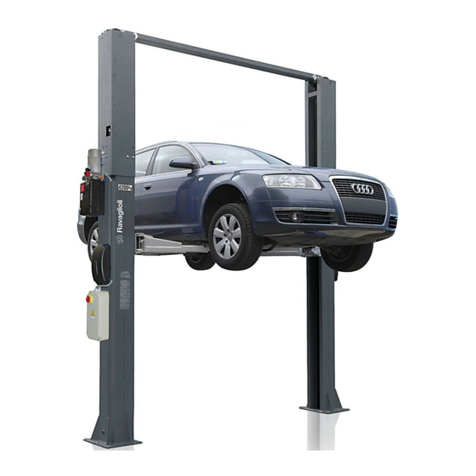
  9. rav KPH 370.42LLK User manual

rav KPH 370.42LLK User manual

Redatto da ESSEBI (Bologna)
ITALIANO: ISTRUZIONI ORIGINALI
ENGLISH: TRANSLATION OF THE ORIGINAL INSTRUCTIONS
DEUTSCH: ÜBERSETZUNG DER ORIGINALANLEITUNG
FRANÇAIS: TRADUCTION DES INSTRUCTIONS ORIGINALES
ESPAÑOL: TRADUCCIÓN DE LAS INSTRUCCIONES ORIGINALES
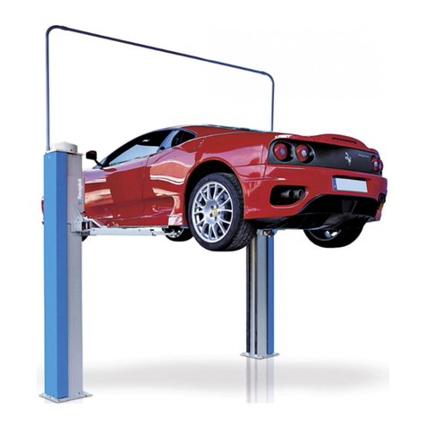
KPH 370.42LLK
SOLLEVATORE A 2 COLONNE
2 POST LIFT
HEBEBÜHNE MIT 2 SÄULEN
ELEVATEUR A 2 COLONNES
ELEVADOR DE 2 COLUMNAS
0484-M015-1
0484-M015-1 Rev. n. 1 (05-2018)
- Per eventuali chiarimenti interpellare il più vicino rivenditore oppure rivolgersi direttamente a
Servizio assistenza tecnica: RAVAGLIOLI S.p.A - 40037 Pontecchio Marconi - Bologna Italia - Via 1° Maggio, 3
Tel. (+39) 051 6781511 - fax (+39) 051 846349 - e-mail: [email protected]
- For any further information please contact your local dealer or call:
RAVAGLIOLI S.p.A. - After Sales Service - Via 1° Maggio, 3 - 40037 Pontecchio Marconi - Bologna - Italy
Phone (+39) 051 6781511 - Fax (+39) 051 846349- e-mail: [email protected]
- Im Zweifelsfall ober bei Rückfragen wenden Sie sich bitte an den nächsten Wiederverkäufer oder direkt an:
RAVAGLIOLI S.p.A. - Kundendienst - Via 1° Maggio, 3 - 40037 Pontecchio Marconi - Bologna - Italien
Telefon (+39) 051 6781511 - Fax (+39) 051 846349 - e-mail: [email protected]
- Pour tout renseignement complémentaire s’adresser au revendeur le plus proche ou directement à:
RAVAGLIOLI S.p.A. - Service Après-Vente - Via 1° Maggio, 3 - 40037 Pontecchio Marconi - Bologna - Italie
Tél. (+39) 051 6781511 - Fax: (+39) 051 846349 - e-mail: [email protected]
- En caso de dudas, para eventuales aclaraciones, póngase en contacto con el distribudor más próximo ó diríjasie directamente a:
RAVAGLIOLI S.p.A. - Servicio Post Venta - Via 1° Maggio, 3 - 40037 Pontecchio Marconi - Bologna - Italia
Tel. (+39) 051 6781511 - Fax (+39) 051 846349 - e-mail: [email protected]
All manuals and user guides at all-guides.com
2
¡ATENCIÓN!
- El presente manual forma parte integrante del producto y por lo tanto deberá seguir toda la vida
operativa del elevador.
Conservarlo, por lo tanto, en un sitio conocido, fácilmente accesible y consultarlo cada vez que
surjan dudas. Todos los operadores que utilizan el elevador tienen que poder leer el manual.
Cualquier daño derivado de la falta de respeto de las indicaciones contenidas en este manual y
de un uso impropio del elevador exime al fabricante de cualquier responsabilidad.
ATTENTION!
- La présente notice est partie intégrante du produit; elle devra accompagner l’élévateur pendant
toute la durée de son fonctionnement. Elle doit donc être conservée dans un endroit connu et
facilement accessible et être consultée au moindre doute. Tous les opérateurs qui utilisent le
pont doivent pouvoir lire la notice. Tout dommage résultant de la non observation des indications
contenues dans le présent manuel et suite à une utilisation impropre de l’élévateur dégage le
fabricant de toute responsabilité.
ACHTUNG!
- Diese Anleitung ist ergänzender Bestandteil des Produktes und muss zusammen mit der
Hebebühne sorgfältig aufbewahrt werden.
DieAnleitung an einem bekannten und leicht zugänglichen Ort aufbewahren und bei Bedarf zu Rate ziehen.
Alle Bediener des Geräts müssen zwecks Einsichtnahme Zugang zurAnleitung haben. JedeArt von Schaden,
der auf Nichtbeachtung der in diesem Handbuch enthaltenen Anweisungen und auf unsachgemäßen
Gebrauch der Hebevorrichtung zurückzuführen ist, entbindet den Hersteller von jeder Verantwortung.
CAUTION!
-This manual is an integral part of the product and must be kept together with the lift throughout
its lifetime.
It should therefore be kept in an easily accessible and familiar place and consulted when in doubt.
All product operators must be able to read the manual. The manufacturer is exempted from any
responsibility for damage caused by failing to follow the indications in this manual and by improper
use of the lifting device.
ATTENZIONE!
-Il presente manuale costituisce parte integrante del prodotto, dovrà seguire tutta la vita operativa
del sollevatore.
Conservarlo, quindi, in luogo noto e facilmente accessibile e consultarlo ogni qualvolta sorgano
dubbi. Tutti gli operatori al prodotto devono poter leggere il manuale. Ogni danno derivante dalla
mancata osservanza delle indicazioni contenute nel presente manuale e da un uso improprio del
sollevatore esime il costruttore da ogni responsabilità.
0484-M015-1
All manuals and user guides at all-guides.com
3
S
SIMBOLI SYMBOLS ZEICHEN SYMBOLES SIMBOLOS
Sollevamento
dall’alto
Lifting from above Anheben von oben Levage par le haut Elevación por la
parte superior
Movimentazione
con carrello
elevatore o
transpallets
Moving with fork lift
truck or transpallets
Transport mit
Gabelstapler
oder auf
Palettenhubwagen
Déplacement avec
chariot élévateur ou
transpalette
Desplazamiento con
carretilla elevadora
o transpaletas
Indossare guanti da
lavoro
Wear working
gloves
Der Arbeit
angemessene
Handschuhe tragen
Porter des gants de
travail
Colocarse guantes
de trabajo
Calzare scarpe da
lavoro
Wear working shoes Der Arbeit
angemessene
Schuhe tragen
Mettre des
chaussures de
travail
Usar zapatos de
trabajo
Non passare nè
sostare sotto carichi
sospesi
Do not walk or stay
beneath suspended
loads
Sich nicht unter
gehobener Last
aufhalten oder
durchgehen
Ne pas passer
ni s’arrêter
au-dessous
des charges
suspendues
No pasar ni
permanecer
debajo de cargas
suspendidas
Personale
specializzato
Specialist sta󰀨 Qualiziertes
Fachpersonal
Personnel qualié Personal
especializado
Attenzione! Caution! Achtung! Attention ! iAtención!
Organi meccanici in
movimento
Working
mechanical parts
Mechanische
Organe in
Bewegung
Organes
mécaniques en
mouvemen
Órganos mecánicos
en movimiento
Schiacciamento Crushing Quetschgefahr Risques
d’écrasement
Aplastes
Obbligo Obligation Picht Obligation Obligación
SIMBOLOGIA UTILIZZATA NEL MANUALE
SYMBOLS USED IN THE MANUAL
IN DER BEDIENUNGSANLEITUNG VERWENDETE ZEICHEN
SYMBOLES UTILISES DANS LA NOTICE
SIMBOLOS UTILIZADOS EN EL MANUAL
0484-M015-1
All manuals and user guides at all-guides.com
4
INDICE I
4.3 BETRIEBSTÜCHTIGKEIT
5. KONTROLLE DER
MINDESTERFORDERNISSEN FÜR DEN
AUFSTELLUNGSORT
6. INSTALLATIONSANWEISUNGEN
6.1 INSTALLATIONSANFORDERUNGEN
6.2 KLEINTEILE UND ZUBEHÖRTEILE
FÜR DIE INSTALLATION
6.3 INSTALLATIONSANLEITUNG
6.4 KONTROLLE DER SPANNUNG
6.5 NETZANSCHLUSS
6.6 PRÜFEN DER KORREKTEN
PHASENSE QUENZ
6.7 KOMPLETTIERUNG UND KONTROLLE
6.8 ARMFESTSTELLVORRICHTUNG
6.9 ÖLPEGELKONTROLLE
6.10 LUFT AUS DEM HYDRAULIKSYSTEM
6.11 DEMONTAGE
7. ANWEISUNGEN FÜR DIE BEDIENUNG DER
HEBEBÜHNE
7.1 UNSACHGEMÄSSE BEDIENUNG DERN
HEBEBÜHNE
7.2 GEBRAUCH VON ZUBEHÖRTEILEN
7.3 SCHULUNG DES
BEDIENUNGSPERSONALS
7.4 VORSICHTSMASSNAHMEN
7.5 DIE STEUERUNGEN UND IHRE
FUNKTIONEN
7.6 NOT-AUS-PROZEDUR SENKEN BEI
STROMAUSFALL
8. BETRIEBSSTÖRUNGEN
9. WARTUNG
9.1 GLEITBAHNEN
9.2 KABEL UND RIEMENSCHEIBEN
9.3 PEGELKONTROLLE
9.4 KONTROLLE DER
SICHERHEITSKLINKEN
10. EINLAGERUNG
10.1 VERSCHROTTUNG
11. ELEKTROANLAGE
12. HYDRAULIKANLAGE
KENNZEICHNUNGSDATENDERMASCHINE
ERSATZTEILELISTEN
KONFRMITÄTSERKLÄRUNG
0. ALLGEMEINE
SICHERHEITSVORSCHRIFTEN
1. SICHERHEITSEINRICHTUNGEN
1.1 VERRIEGELBARERHAUPTSCHALTER
1.2 TOTMANN-SYSTEM
1.3 EINRICHTUNG GEGEN ZUFÄLLIGES
ABSENKEN
1.4 VORRICHTUNG GEGEN
ELEKTRISCHE ÜBERLASTUNG
1.5 ÜBERLASTUNGSSCHUTZVENTIL
1.6 ARMDREHSPERRVORRICHTUNG
1.7 HINWEISE ZU DEN RESTRISIKEN
1.8 AUF DER HEBEBÜHNE VORHANDENE
GEFAHRENZEICHEN
2. BESTIMMUNGSGEMÄSSE
VERWENDUNG
3. TECHNISCHE DATEN
3.1 TRANSPORT UND VORINSTALLATION
4. BESCHREIBUNG DER HEBEBÜHNE
4.1 TECHNISCHE
HAUPTEIGENSCHAFTEN
4.2 STEUERUNGEN DER HEBEBÜHNE
INHALTSVERZEICHNIS
4.3 SUITABILITY FOR USE
5. CHECKING THE MINIMUM
REQUIREMENTS FOR THE PLACE OF
INSTALLATION
6. INSTALLATION INSTRUCTIONS
6.1 INSTALLATION REQUIREMENTS
6.2 COMPONENTS AND ACCESSORIES
FOR INSTALLATION
6.3 INSTALLATION INSTRUCTIONS
6.4 VOLTAGE CHECK
6.5 CONNECTING UP TO THE MAINS
6.6 PHASE SEQUENCE CHECK
6.7 COMPLETION AND CHECK
6.8 ARM STOP
6.9 CHECKING THE OIL LEVEL
6.10 AIR BLEEDING OUT THE
HYDRAULIC CIRCUIT
6.11 DISMANTLING
7. INSTRUCTIONS FOR USING THE LIFT
7.1 IMPROPER USE OF THE LIFT
7.2 USE OF ACCESSORIES
7.3 STAFF TRAINING
7.4 IMPORTANT CHECKS TO BE MADE
7.5 DESCRIPTION AND FUNCTION OF
CONTROLS
7.6 EMERGENCY PROCEDURE:
EMERGENCY DROP WITH POWER
OFF
8. TROUBLESHOOTING
9. MAINTENANCE
9.1 SLIDEWAYS
9.2 CABLES AND PULLEYS
9.3 CHECKING OIL LEVEL
9.4 CHECKING THE SAFETY CATCHES
10. STORAGE
10.1 SCRAPPING
11. ELECTRICAL INSTALLATION
12. HYDRAULIC SYSTEM
MACHINE IDENTIFICATION DATA
SPARE PARTS TABLES
DECLARATION OF CONFORMITY
0. GENERAL SAFETY PRECAUTIONS
1. SAFETY DEVICES
1.1 PADLOCKABLE MAIN SWITCH
1.2 DEADMAN DEVICE
1.3 DEVICE TO PREVENT ACCIDENTAL
DESCENT
1.4 DEVICE TO PREVENT ELECTRIC
OVERCHARGES
1.5 OVERLOAD VALVE
1.6 ARM ANTI-ROTATION DEVICE
1.7 INDICATION OF OUTSTANDING
RISKS
1.8 PICTOGRAMS ON LIFT
2. INTENDED USE
3. TECHNICAL DATA
3.1 PRE-INSTALLATION AND
MOVEMENT
4. DESCRIPTION OF LIFT
4.1 MAIN TECHNICAL SPECIFICATIONS
4.2 LIFT CONTROLS
CONTENTS
4.2 COMANDI DEL SOLLEVATORE
4.3 ATTITUDINE ALL’IMPIEGO
5. VERIFICA DEI REQUISITI MINIMI
RICHIESTI PER LUOGO DI
INSTALLAZIONE
6. ISTRUZIONI PER L’INSTALLAZIONE
6.1 REQUISITI PER L’INSTALLAZIONE
6.2 COMPONENTI E ACCESSORI PER
INSTALLAZIONE
6.3 ISTRUZIONI DI MONTAGGIO
6.4 CONTROLLO TENSIONE
6.5 ALLACCIAMENTO ALLA RETE
6.6 VERIFICA CORRETTA SEQUENZA
FASI
6.7 COMPLETAMENTO E CONTROLLO
6.8 ARRESTO BRACCIO
6.9 CONTROLLO LIVELLO OLIO
6.10 SPURGO DELL’ARIA IMPIANTO
IDRAULICO
6.11 SMONTAGGIO
7. ISTRUZIONI PER L’USO DEL
SOLLEVATORE
7.1 USO IMPROPRIO DEL SOLLEVATORE
7.2 USO DI ACCESSORI
7.3 ADDESTRAMENTO DEL
PERSONALE PREPOSTO
7.4 PRECAUZIONI D’USO
7.5 IDENTIFICAZIONE DEI COMANDI E
LORO FUNZIONE
7.6 PROCEDURA DI EMERGENZA:
DISCESA IN ASSENZA DI TENSIONE
8. INCONVENIENTI
9. MANUTENZIONE
9.1 GUIDE DI SCORRIMENTO
9.2 CAVI E PULEGGE
9.3 CONTROLLO LIVELLO OLIO
9.4 CONTROLLO DISPOSITIVO
MECCANICO DI SICUREZZA
10. ACCANTONAMENTO
10.1 ROTTAMAZIONE
11. IMPIANTO ELETTRICO
12. IMPIANTO IDRAULICO
DATI DI IDENTIFICAZIONE DELLA
MACCHINA
TAVOLE PEZZI DI RICAMBIO
DICHIARAZIONE DI CONFORMITÀ
0. NORME GENERALI DI SICUREZZA
1. DISPOSITIVI DI SICUREZZA
1.1 INTERRUTTORE GENERALE
LUCCHETTATO
1.2 SISTEMA A UOMO PRESENTE
1.3 DISPOSITIVO CONTRO LADISCESA
ACCIDENTALE
1.4 DISPOSITIVO CONTRO I
SOVRACCARICHI ELETTRICI
1.5 VALVOLA DI SICUREZZA CONTRO I
SOVRACCARICHI
1.6 DISPOSITIVO ANTIROTAZIONE DEI
BRACCI
1.7 RISCHI RESIDUI
1.8 PITTOGRAMMI PRESENTI SUL
SOLLEVATORE
2. DESTINAZIONE D’USO
3. DATI TECNICI
3.1 MOVIMENTAZIONE E
PREINSTALLAZIONE
4. DESCRIZIONE DEL SOLLEVATORE
4.1 CARATTERISTICHE TECNICHE
PRINCIPALI
0484-M015-1
All manuals and user guides at all-guides.com
5
I
5. COMPROBACIÓN DE LA EXISTENCIA DE
LOS REQUISITOS MÍNIMOS REQUERIDOS
PARA EL SITIO DE LA INSTALACIÓN
6. INSTRUCCIONES PARA LA INSTALACIÓN
6.1 REQUISITOS PARA LA INSTALACIÓN
6.2 COMPONENTES Y ACCESORIOS
DE INSTALACIÓN
6.3 INSTRUCCIONES DE INSTALACIÓN
6.4 CONTROL DE TENSIÓN
6.5 ENLACE A LA RED
6.6 CONTROL CORRECTA SECUENCIA
FASES
6.7 TERMINACIÓN DE LA INSTALACIÓN
Y CONTROL
6.8 BLOQUEO BRAZO
6.9 CONTROL NIVEL ACEITE
6.10 SALIDA DEL AIRE DEL SISTEMA
HIDRÁULICO
6.11 DESMONTAJE
7. INSTRUCCIONES PARA EL USO DEL
ELEVADOR
7.1 USO IMPROPIO DEL ELEVADOR
7.2 USO DE ACCESORIOS
7.3 FORMACIÓN DEL PERSONAL
AUTORIZADO
7.4 PRECAUCIONES DURANTE EL USO
7.5 IDENTIFICACIÓN DE LOS MANDOS
Y SUS FUNCIONES
7.6 PROCEDIMIENTO DE EMERGENCIA:
DESCENSO EN AUSENCIA DE
TENSIÓN
8. INCONVENIENTES
9. MANTENIMIENTO
9.1 GUÍAS DESLIZANTES
9.2 CABLES Y POLEAS
9.3 CONTROL NIVEL
9.4 CONTROL PALANCA ROTATORIA
10. DESUSO
10.1 REDUCCIÓN A RESIDUOS
11. ESQUEMA ELECTRICO
12. INSTALACIÓN HIDRÁULICA
DATOS DE IDENTIFICACION DE LA
MAQUINA
TABLAS DE LAS PIEZAS DE REPUESTO
DECLARACIÓN DE CONFORMIDAD
ÍNDICE
COMPOSICIÓN DEL MANUAL
82 páginas (incluidas las portadas)
0. NORMAS GENERALES DE SEGURIDAD
1. DISPOSITIVOS DE SEGURIDAD
1.1 INTERRUPTOR GENERAL BAJO
CANDADO
1.2 SISTEMA “HOMBRE MUERTO”
1.3 DISPOSITIVO CONTRA EL
DESCENSO ACCIDENTAL
1.4 DISPOSITIVO CONTRA LAS
SOBRECARGAS ELÉCTRICAS
1.5 VÁLVULA DE SEGURIDAD CONTRA
LAS SOBRECARGAS
1.6 DISPOSITIVO ANTIRROTACIÓN DE
LOS BRAZOS
1.7 INDICACIONES DE LOS RIESGOS
RESIDUOS
1.8 ICTOGRAMAS EN EL ELEVADOR
2. DESTINACIÓN DE USO
3. DATOS TÉCNICOS
3.1 DESPLAZAMIENTOYPREINSTALACIÓN
4. DESCRIPCIÓN DEL ELEVADOR
4.1 CARACTERISTICAS TÉCNICAS
PRINCIPALES
4.2 MANDOS DEL ELEVADOR
4.3 APTITUD PARA EL EMPLEO
CARACTÉRISTIQUES TECHNIQUES
4.2 COMMANDES DU PONT ÉLÉVATEUR
4.3 APTITUDE À L’EMPLOI
5. VERIFICATION DES CARACTERISTIQUES
MINIMES D’INSTALLATION
6. INSTRUCTIONS POUR L’INSTALLATION
6.1 CONDITIONS REQUISES POUR
L’INSTALLATION
6.2 DÉPLACEMENT ET PRÉ-
INSTALLATION
6.3 INSTRUCTIONS DE MONTAGE
6.4 CONTRÔLE DE LA TENSION
6.5 CONNEXION AU RÉSEAU
6.6 VÉRIFI CATION SÉQUENCE
PHASES
6.7 COMPLÈTEMENT DE
L’INSTALLATION ET CONTRÔLE
6.8 BLOCAGE DU BRA
6.9 CONTRÔLE DU NIVEAU D’HUILE
6.10 EXPULSER L’AIR DU CIRCUIT
HYDRAULIQUE
6.11 DÉMONTAGE
7. MODE D’EMPLOI DU PONT ELEVATEUR
7.1 UTILISATION INCORRECTE DU
PONT ÉLÉVATEUR
7.2 UTILISATION D’ACCESSOIRES
7.3 FORMATION DU PERSONNEL
PRÉPOSÉ
7.4 PRÉCAUTIONS POUR L’EMPLOI
7.5 IDENTIFICATION ET FONCTION DES
COMMANDES
7.6 PROCEDURE DE SECOURS:
DESCENTE EN CAS D’ABSENCE DE
TENSION
8. PANNES EVENTUELLES
9. ENTRETIEN
9.1 GLISSIÈRES
9.2 CÂBLES ET POULIES
9.3 CONTRÔLE NIVEAU
9.4 CONTRÔLE MARTELETS
10. STOCKAGE
10.1 MISE À LA FERRAILLE
11. INSTALLATION ÈLECTRIQUE
12. INSTALLATION HYDRAULIQUE
DONNÉES D’IDENTIFICATION DE LA
MACHINE
PLANCHES DES PIECES DE RECHANGE
DÉCLARATION DE CONFORMITÉ
0. NORMES GENERALES DE SECURITÈ
1. DISPOSITIFS DE SECURITE
1.1 INTERRUPTEUR PRINCIPAL
VERROUILLABLE
1.2 SYSTÈME DE SÉCURITÉ “HOMME
MORT”
1.3 DISPOSITIF DE SÉCURITÉ CONTRE
LA DESCENTE ACCIDENTELLE
1.4 DISPOSITIF CONTRE LES
SURCHARGES ÉLECTRIQUES
1.5 VANNE DE SÉCURITÉ CONTRE LES
SURCHARGES
1.6 DISPOSITIF DE PROTECTION
CONTRE LA ROTATION DES BRAS
1.7 INFORMATIONS SUR LES RISQUES
RÉSIDUELS
1.8 PICTOGRAMMES PRÉSENTS SUR
L’ÉLÉVATEUR
2. DESTINATION D’USAGE
3. DONNEES TECHNIQUES
3.1 DÉPLACEMENT ET PRÉ-
INSTALLATION
4. DESCRIPTION DU PONT ELEVATEUR
4.1 PRINCIPALES
INDEX
COMPOSITION DU MANUEL
82 pages (y compris les couvertures)
ZUSAMMENSETZUNG DER ANLEITUNG
82 Seiten (inkl. Deckblätter)
THIS MANUAL CONSISTS OF
82 pages (covers included)
COMPOSIZIONE DEL MANUALE
82 pagine (comprese le copertine)
0484-M015-1
All manuals and user guides at all-guides.com
6
0
0. NORMAS GENERALES DE SEGURIDAD
El uso del elevador sólo está permitido a personal
capacitado a propósito y sólo después de haber leído y comprendido
el presente manual; el operador tiene que estar autorizado por quien
desempeña el cargo de responsable de la instalación.
Están prohibidas las alteraciones o modi caciones del elevador
y de los dispositivos de seguridad; en caso de que se verique lo
descrito anteriormente, se considera al constructor no responsable
de los daños derivados.
Además, hay que seguir las siguientes indicaciones:
- usar únicamente accesorios y repuestos del fabricante;
- la instalación tiene que ser realizada única y exclusivamente por
personal autorizado y cualicado.
- controlar que durante la fase de subida y bajada no se veri quen
condiciones de peligro: de ser así, detener la máquina y eliminar las
causas de emergencia;
- los brazos tienen que estar colocados en los puntos predispuestos
en el vehículo; antes de la subida, comprobar la estabilidad del
vehículo, comprobar durante la fase de subida y bajada el punto de
apoyo del vehículo;
- Está terminantemente prohibido subirse o pararse en los órganos
de elevación.
- después de la elevación colocar el interruptor en “O”
- antes de la elevación, comprobar con el adhesivo “diagrama de
carga” que la carga esté correcta.
0. NORMES GENERALES DE SECURITÈ
Le pont élévateur ne peut être utilisé que par un
personnel ayant suivi une formation appropriée et ayant lu et compris
le contenu de la présente notice; l’opérateur doit être autorisé par la
personne responsable de l’installation.
Il est strictement interdit de manipuler ou de modi er l’élévateur et
les dispositifs de sécurité; toute dérogation à ces instructions décline
le fabricant de toute responsabilité.
Respecter entre autres les instructions suivantes:
- n’utiliser que des accessoires et pièces de rechange Originales;
- l’installation doit être prise en charge par un personnel autorisé et
qualié;
- contrôler l’absence de toute condition de danger pendant les
manoeuvres de montée et de descente; en cas de danger, arrêter
immédiatement l’élévateur et éliminer les causes à l’origine de la
condition d’urgence;
- les bras doivent être positionnés aux points prévus par le fabricant
du véhicule: véri er la stabilité du véhicule avant d’entreprendre la
manoeuvre de levage; pendant les phases de montée et de descente,
véri er le point d’appui du véhicule;
- Il est strictement interdit de monter ou de s’arrêter sur les organes
de levage;
- une fois le levage terminé, positionner l’interrupteur sur le “0”;
- avant d’e󰀨ectuer le levage, contrôler à l’aide du “diagramme de
chargement” que le chargement soit correct.
0. ALLGEMEINE SICHERHEITSVORSCHRIFTEN
Die Hebebühne darf ausschliesslich von geschultem
Fachpersonal
bedient werden und erst nachdem die Bedienungsanleitung
aufmerksam gelesen und verstanden worden ist. Der Bediener muss
zur Bedienung der Hebebühne von der Person autorisiert werden,
die die Verantwortung für die Anlage trägt.
Unbefugtes Betätigen und Änderungen an der Hebebühne sowie an
den Sicherheitseinrichtungen sind verboten. Bei Verstoss gegen diese
Vorschriften lehnt der Hersteller jede Verantwortung für die daraus
entstehenden Schäden ab.
Darüber hinaus sind folgende Verhaltensmassregeln einzuhalten:
- Es dürfen nur Originalzubehör- und Ersatzteilebenutzt werden;
- die Hebebühne ist durch autorisiertes Fachpersonal aufzustellen;
- sicherstellen, dass beim Hoch- und Herunterfahren der Hebebühne
keine gefährliche Situationen entstehen; ggf. die Hebebühne sofort
anhalten und die Gefährdungen beseitigen;
- die Arme sind auf die Punkte zu positionieren, die auf dem Fahrzeug
vorgesehen sind; vor dem Hublauf die Stabilität des Fahrzeugs
kontrollieren;
während des Hoch- und Herunterfahrens den Aufnahmepunkt des
Fahrzeugs kontrollieren;
- Es ist verboten, auf die Hubelemente zu steigen oder sich auf
diesen aufzuhalten.
- nach der Hochfahrt den Schalter auf “0” setzen;
- vor dem Anheben des Fahrzeugs durch Einsichtnahme des
Klebeschildes “Lastschema”
0. GENERAL SAFETY PRECAUTIONS
The lift should only be used by properly trained
personnel and onlyafter reading and understanding this manual. The
operator must be authorised by the person in charge of the plant.
Tampering with or making changes to the lift and safety devices is
forbidden. Failure to comply will result in the manufacturer being
released from all liability for any resulting damages.
Also follow these instructions:
- only use manufacturer’s accessories and spares;
- installation must be performed by authorised and professional
personnel;
- make sure no hazardous situations occur during up or down
movement
of the lift. If they do, stop the lift immediately and remedy the causes
of the emergency;
- the arms must be positioned at the vehicle points provided. Before
lifting, check vehicle stability. During up or down movement, check
the vehicle load bearing point;
- standing on the lifting mechanisms is forbidden;
- after lifting, position the switch on “0”;
- before lifting, check the load is correct by means of the “load
diagram” adhesive.
0. NORME GENERALI DI SICUREZZA
L’uso del sollevatore è consentito solo a personale
appositamente addestrato e solo dopo aver letto e compreso il
presente manuale;
l’operatore deve essere autorizzato da chi ricopre il ruolo di
responsabile dell’impianto.
Sono vietate manomissioni o modiche al sollevatore e ai dispositivi di
sicurezza; nel caso in cui si verichi quanto sopra scritto il costruttore
si ritiene sollevato dai danni derivati.
Seguire inoltre le seguenti indicazioni:
- usare solo accessori e ricambi del costruttore;
- l’installazione deve essere fatta da personale autorizzato e
qualicato;
- controllare che durante la fase di salita e discesa non si verichino
condizioni di pericolo; in tal caso arrestare immediatamente il
sollevatore e rimuovere le cause di emergenza;
- i bracci devono essere posizionati sui punti predisposti del veicolo;
prima della salita vericare la stabilità del veicolo; vericare durante
a fase di salita e discesa il punto di appoggio del veicolo;
- è vietato salire o sostare sugli organi di sollevamento;
- dopo il sollevamento posizionare l’interruttore sullo “0”;
- prima di sollevare vericare con l’adesivo “diagramma di carico”
che il carico sia corretto.
0484-M015-1
All manuals and user guides at all-guides.com
7
0
0484-M015-1
All manuals and user guides at all-guides.com
8
1
1. DISPOSITIVOS DE SEGURIDAD
1.1 Interruptor general bajo candado
1.2 Sistema “hombre muerto”
El elevador tiene un sistema de tipo “hombre muerto”, las operaciones
de subida o descenso son interrumpidas de immediato al soltar el
de mando.
1.3 Dispositivo contra el descenso accidental
El puente cuenta con un dispositivo a inserción automática.
Este impide al elevador de descender por más de 100 mm en el
caso exista cualquier defecto o pérdida en el circuito hidráulico del
elevador.
1.4 Dispositivo contra las sobrecargas eléctricas
El puente cuenta con un dispositivo megnetotérmico.
Se puede también verificar la desactivación del dispositivo
megnetotérmico el rearme se efectúa manualmente automático en
el panel electrico.
1. DISPOSITIFS DE SECURITE
1.1 Interrupteur principal verrouillable
1.2 Système de sécurité “homme mort”
Le pont est équipé d’un système de fonctionnement de type “homme
mort”: les manoeuvres de montée ou de descente s’interrompent
immédiatement lorsque de commande est relâché.
1.3 Dispositif de sécurité contre la descente accidentelle
Le pont est équipé d’un dispositif à enclenchement automatique.
Ce dernier empêche le pont élévateur de descendre de plus de 100
mm en cas de défaut quelconque ou de perte au niveau du circuit
hydraulique de levage.
1.4 Dispositif contre les surcharges électriques
Le pont est doté d’un interrupteur magnétothermique.
Si l’interrupteur magnétothermique se déconnecte le réarmement
doit être e󰀨ectué manuellement à l’intérieur du panneau électrique.
1. SICHERHEITSEINRICHTUNGEN
1.1 Verriegelbarer Hauptschalter
1.2 Totmann-System
Die Hebebühne funktioniert mit dem Totmann-System. Die Auf- und
Abwärtsbewegungen werden beim Loslassen der Steuerung sofort
unterbrochen.
1.3 Einrichtung gegen zufälliges Absenken
Die Hebebühne ist mit einer automatisch einsetzenden Einrichtung
ausgerüstet. Diese Einrichtung verunmöglicht der Hebebühne, bei
einem beliebigen Mangel oder undichtem Hubhydraulikkreis mehr
als 100 mm herunterzufahren.
1.4 Vorrichtung gegen elektrische Überlastung
Die Bühne ist mit einem magnetothermischem Schalter ausgestattet.
Sollte der magnetothermische Schalter ausgeschaltet werden, muss
die Rückstellung manuell über das elektrische Bedienpult erfolgen.
1. SAFETY DEVICES
1.1 Padlockable main switch
1.2 Deadman device
The lift is equipped with a “deadman” type operative system so that
the rise or descent operations are immediately stopped when the
command is released.
1.3 Device to prevent accidental descent
The lift is equipped with an automatically activated device.
This prevents the lift descending more than 100 mm when there is
a defect or leak in the hydraulic lifting circuit.
1.4 Device to prevent electric overcharges
The lift is equipped with a magneto-thermal switch.
The magneto-thermal switch might be disabled. This cab be manually
reset inside the electric panel.
1. DISPOSITIVI DI SICUREZZA
1.1 Interruttore generale lucchettabile
1.2 Sistema a uomo presente
Il ponte è dotato di un sistema operativo del tipo “uomo presente”,
le operazioni di salita o di discesa, sono immediatamente interrotte
al rilascio del comando.
1.3 Dispositivo contro la discesa accidentale
Il ponte è dotato di un dispositivo ad inserimento automatico.
Questo impedisce al sollevatore di scendere per più di 100 mm
qualora ci sia un qualunque difetto o perdita nel circuito idraulico di
sollevamento.
1.4 Dispositivo contro i sovraccarichi elettrici
Il ponte è dotato di un interruttore magnetotermico.
Se si verica il disinserimento dell’interruttore magnetotermico il
riarmo deve essere e󰀨ettuato manualmente all’interno del pannello
elettrico.
0484-M015-1
All manuals and user guides at all-guides.com
9
1
1.5 Válvula de seguridad contra las sobrecargas
Impide el levantamiento de cargas que exceden la capacidad
del elevador.
1.6 Dispositivo antirrotación de los brazos
El dispositivo bloquea automáticamente la rotación de los brazos en
el momento en que comienza la carrera de subida.
1.5 Vanne de sécurité contre les surcharges
Empêche le levage de charges excédant la capacité du pont-
élévateur.
1.6 Dispositif de protection contre la rotation des bras
Le dispositif bloque la rotation des bras automatiquement dès que
l’élévateur commence sa course de montée.
1.5 Überlastungsschutzventil
Hindert an einem Heben von der Tragleistung der Hebebühne
übermäßigen Lasten.
1.6 Armdrehsperrvorrichtung
Diese Vorrichtung blockiert automatisch die Armdrehung, sobald die
Hebebühne hochfährt.
1.5 Overload valve
Prevents lifting of loads exceeding lift capacity.
1.6 Arm anti-rotation device
This device automatically stops arm rotation as soon as elevation
starts.
1.5 Valvola di sicurezza contro i sovraccarichi
Impedisce il sollevamento di carichi eccedenti la portata del
sollevatore.
1.6 Dispositivo antirotazione dei bracci
Il dispositivo blocca automaticamente la rotazione dei bracci appena
inizia la corsa di salita.
0484-M015-1
All manuals and user guides at all-guides.com
10
1
1 99990492 TARGHETTA PORTATA 3000 Kg PLATE
2 TARGA MATRICOLA PLATE
3 99990758 TARGHETTA PERICOLO PLATE
4 999909850 TARGHETTA ISTRUZIONI PLATE
5 999912530 TARGHETTA 220V 60Hz 1Ph PLATE
999912430 TARGHETTA 230V 60Hz 1Ph PLATE
999912520 TARGHETTA 380V 60Hz 3Ph PLATE
999912510 TARGHETTA 220V 60Hz 3Ph PLATE
999912390 TARGHETTA 230V 50Hz 3Ph PLATE
999912380 TARGHETTA 400V 50Hz 3Ph PLATE
6 999908141 TARGHETTA RIPARTIZIONE CARICO (3000 kg) PLATE
9(,&+/(6/,)7
02'(/
&$3$&,7<.*

3257$7$
0$;









4 33
NJ
3
NJ
3
NJ
&
PP
5,3$57,=,21('(/&$5,&2
/2$'',675,%87,21
*(:,&+79(57(,/81*
5(3$57,7,21'(&+$5*(
5(3$57,&,21'(/$&$5*$
33
33
4
&




9(,&+/(6/,)7
02'(/
5$(< 6(5,$/1q
5$(<
6(5,$/1q












0484-M015-1
All manuals and user guides at all-guides.com
11
1
1.7 Indicaciones de los riesgos residuos
NUESTRO ELEVADOR SE HA CONSTRUIDO APLICANDO NORMAS SEVERAS PARA RESPONDER A LOS REQUISITOS EXIGIDOS
POR LAS NORMATIVAS PERTINENTES.
EL ANÁLISIS DE LOS RIESGOS SE EFECTÚO CON EL MÁXIMO CUIDADO Y LOS PELIGROS FUERON, EN LO QUE FUE POSIBLE
ELIMINADOS.
EVENTUALES RIESGOS RESIDUOS SE EVIDENCIAN EN EL PRESENTE MANUAL Y EN LA MÁQUINA MEDIANTE PICTOGRAMAS
DE CUIDADO.
1.8 Pictogramas en el elevador
VER FIG.
EN EL CASO DE QUE ESTOS PICTOGRAMAS SE ESTROPEEN, ES NECESARIO SUSTITUIRLOS, SOLICITÁNDOLOS ALAEMPRESA.
1.7 Informations sur les risques résiduels
L’ÉLÉVATEUR OBJET DE LA PRÉSENTE NOTICE A ÉTÉ FABRIQUÉ DANS LE RESPECT DE NORMES SÉVÈRES POUR RÉPONDRE
AUX QUALITÉS REQUISES PAR LES DIRECTIVES RÉGISSANT CES APPAREILS.
UNE ANALYSE ATTENTIVE DES RISQUES A ÉTÉ RÉALISÉE ET LES DANGERS ONT ÉTÉ ÉLIMINÉS DANS LA MESURE DU POSSIBLE
LES RISQUES RÉSIDUELS ÉVENTUELS ONT ÉTÉ SIGNALÉS DANS LA PRÉSENTE NOTICE ET SUR LA MACHINE AU MOYEN DE
PICTOGRAMMES.
1.8 Pictogrammes présents sur l’élévateur
VOIR FIGURE
LES PICTOGRAMMES ENDOMMAGÉS DOIVENT ÊTRE REMPLACÉS. S’ADRESSER DIRECTEMENT À LA SOCIÉTÉ.
1.7 Hinweise zu den Restrisiken
BEI DER ENTWICKLUNG UNSERER HEBEBÜHNE WURDEN STRENGE NORMEN ZUR ÜBEREINSTIMMUNG MIT DEN IN DEN
EINSCHLÄGIGEN RICHTLINIEN VORGESCHRIEBENEN ANFORDERUNGEN ANGEWANDT.
DIE ANALYSE DER RISIKEN WURDE MIT GRÖSSTER SORGFALT AUSGEFÜHRT UND DIE GEFÄHRDUNGEN WURDEN, SOWEIT
MÖGLICH, BESEITIGT.
EVENTUELLE RESTRISIKEN WERDEN IN DIESER BEDIENUNGSANLEITUNG UND AUF DEN GEFAHRENZEICHEN AUF DER
AUSRÜSTUNG ANGEZEIGT.
1.8 Auf der Hebebühne vorhandene Gefahrenzeichen
SIEHE ABB.
EVTL. BESCHÄDIGTE GEFAHRENZEICHEN SIND BEI DER FIRMA ANZUFORDERN UND ZU ERSETZEN.
1.7 Indication of outstanding risks
OUR LIFT HAS BEEN MANUFACTURED ACCORDING TO THE MOST STRINGENT STANDARDS REQUIRED BY APPLICABLE
DIRECTIVES.
RISK ANALYSIS HAS BEEN CAREFULLY MADE AND ALL HAZARDS HAVE, AS FAR AS POSSIBLE, BEEN ELIMINATED. ANY
OUTSTANDING RISKS ARE EVIDENCED IN THIS MANUAL AND ON THE MACHINE BY PICTOGRAMS.
1.8 Pictograms on lift
SEE FIG.
IN THE EVENT OF THESE PICTOGRAMS BEING DAMAGED, THEY MUST BE REPLACED BY NEW ONES AVAILABLE FROM THE
MANUFACTURER.
1.7 Indicazioni dei rischi residui
IL NOSTRO SOLLEVATORE È STATO REALIZZATO APPLICANDO SEVERE NORME PER LA RISPONDENZAAI REQUISITI RICHIAMATI
DALLE DIRETTIVE PERTINENTI.
L’ANALISI DEI RISCHI È STATA EFFETTUATAACCURATAMENTE ED I PERICOLI SONO STATI, PER QUANTO POSSIBILE, ELIMINATI
EVENTUALI RISCHI RESIDUI SONO EVIDENZIATI NEL PRESENTE MANUALE E SULLA MACCHINA MEDIANTE PITTOGRAMMI DI
ATTENZIONE.
1.8 Pittogrammi presenti sul sollevatore
VEDI FIGURA.
NEL CASO CHE QUESTI PITTOGRAMMI SI DANNEGGINO È NECESSARIO SOSTITUIRLI RICHIEDENDOLI AL FABBRICANTE.
0484-M015-1
All manuals and user guides at all-guides.com
12
2
P2
P1 P2
P2 P1
(P1)
P2
(P1)
3000 kg
C
0484-M015-1
All manuals and user guides at all-guides.com
13
2
2. DESTINACIÓN DE USO
El producto está destinado a la elevación de autovehículos; la
capacidad está indicada en la placa de matrícula.
Está permitida la elevación de autovehículos que respondan a las
siguientes características:
- peso no superior a la capacidad del elevador
- distribución de la carga en los puntos de apoyo –VEASE LA TABLA
en la pág. 12
- distancia mínima de los puntos de elevación (carril): (mm.1000 -
3000kg)
Para valores de distancia inferiores, la capacidad del elevador se
reduce. Por tanto, en esos casos y para otros no contemplados en
el presente manual, será conveniente ponerse en contacto con el
fabricante.
- El uso del elevador está permitido exclusivamente en el interior de
locales cerrados, en los que no exista peligro de explosión o incendio.
- El elevador no es adecuado para usos que prevean el lavado de
vehículos.
2. DESTINATION D’USAGE
Le pont élévateur est destiné au levage de véhicules; la portée est
celle indiquée sur la plaque matricule.
Il ne peut être utilisé que pour le levage de véhicules répondant aux
caractéristiques suivantes:
- le poids ne doit pas dépasser la portée du pont élévateur,
- distribution de la charge sur les points d’appui - VOIR TABLEAU
page 12
- distance minimale entre les points de levage (voie):(mm.1000 -
3000kg)
Pour des valeurs de distance inférieures, la portée du pont élévateur
est réduite. Dans ce cas ou d’autres qui ne sont pas prévus dans la
présente notice, il sera opportun de prendre contact avec le fabricant.
- le pont élévateur ne peut être utilisé qu’à l’intérieur de locaux fermés,
à l’abri de tout risque d’explosion ou d’incendie.
- le pont élévateur ne peut être utilisé pour laver les véhicules.
2. BESTIMMUNGSGEMÄSSE VERWENDUNG
Das Produkt ist zum Heben von Fahrzeugen vorgesehen. Die
entsprechende Tragfähigkeit ist auf dem Seriennummernschild
angegeben.
Gestattet wird das Heben von Fahrzeugen, die den folgenden
Anforderungen entsprechen:
- Gewicht, das die Tragfähigkeit der Hebebühne nicht überschreitet.
- Lastverteilung auf den Abstützpunkten – SIEHE TABELLE Seite 12
- Mindestabstand der Hebepunkte (Spurweite): (mm.1000 - 3000kg)
Bei geringerem Abstand wird die Tragfähigkeit der Hebebühne
reduziert.
In solchen und anderen, nicht von dieser Anleitung vorgesehenen
Fällen den Hersteller zu Rate ziehen.
- Die Hebebühne darf ausschliesslich in geschlossenen Räumen,
wo weder Explosions- noch Brandgefahr besteht, gefahren werden.
- Die Hebebühne ist nicht zum Waschen von Fahrzeugen eeignet.
2. INTENDED USE
The product is designed for lifting vehicles. The capacity is indicated
on the serial number plate.
Vehicles having the following characteristics may be lifted:
- weight not exceeding lift capacity
- load distribution on supporting points -SEE TABLE page 12
- minimum distance of pickup points (track):(mm.1000 - 3000kg)
For lower distance values, the lift capacity will be reduced. In this
case or in other cases not covered by this manual, the manufacturer
should be contacted.
- The lift may only be used in enclosed areas where there is no danger
of explosion or  re.
- The lift is not suitable for use where vehicle washing is contemplated.
2. DESTINAZIONE D’USO
Il prodotto è destinato al sollevamento di autoveicoli; la portata è
quella indicata nella targhetta matricola.
E’ consentito il sollevamento di autoveicoli rispondenti ai seguenti
requisiti:
- peso non superiore alla portata del sollevatore
- ripartizione del carico sui punti di appoggio -VEDI TABELLA pag. 12
- distanza minima dei punti di sollevamento (carreggiata): (mm.1000
- 3000kg)
Per valori di distanza inferiori, la portata del sollevatore viene ridotta.
Pertanto in questi casi o per altri non contemplati nel presente
manuale, sarà opportuno contattare il costruttore.
- l’uso del sollevatore è consentito esclusivamente all’interno di locali
chiusi, ove non sussistano pericoli di esplosione o incendio.
- il sollevatore non è idoneo ad un utilizzo che preveda il lavaggio
dei veicoli.
0484-M015-1
All manuals and user guides at all-guides.com
14
3
2922
inside column
3658Overall Width
4105 [4005]
4162 [4062]
2003
135 max
75 min
220
2615
drive-thru
100
802
1262
1262
802
ø
B
C
A
0484-M015-1
A B C
KPH 370.42 LLK 4162
4062 4105
4005 2003
All manuals and user guides at all-guides.com
15
3
0484-M015-1
KPH 370.42 LLK
3. DATI TECNICI Portata Motore trifase Motore monofase Peso Rumorosità
3000 Kg 230/400 V - 50 Hz - 2.6 kW 230 V - 50 Hz -1.5 kW 750 kg ≤70 dB (A)
3. TECHNICAL DATA Capacity Three-phase motor Single-phase motor Weight Noise level
3. TECHNISCHE
DATEN Tragkraft Dreiphasenmotor Einphasenmotor Gewicht Geräus-
chpege
3. DONNEES
TECHNIQUES Portée Moteurs triphasés Moteurs monophasés Poids
Niveau de
bruit
3. DATOS
TÉCNICOS Capacidad Motor Trifásico Motor monofásico Peso Nivel de ruido
All manuals and user guides at all-guides.com
16
4
1 COLONNA COMANDO
2 COLONNA OPPOSTA
3 CARRELLI
4 BRACCI
5 SCATOLA COMANDO
6 MOTORE CENTRALINA IDRAULICA
7 PORTALE
1 CONTROL POST
2 OPPOSITE POST
3 CARRIAGES
4 ARMS
5 CONTROL BOX
6 HYDRAULIC CONTROL UNIT MOTOR
7 GANTRY
1 STEUERSÄULE
2 NEBENSÄULE
3 HUBWAGEN
4 ARME
5 SCHALTSCHRANK
6 MOTOR DER HYDRAULIKZENTRALE
7 PORTAL
1 COLONNE DE COMMANDE
2 COLONNE OPPOSEE
3 CHARIOTS
4 BRAS
5 BOITIER DE COMMANDE
6 MOTEUR CENTRALE HYDRAULIQUE
7 PORTIQUE
1 COLUMNA DE MANDO
2 COLUMNA OPUESTA
3 CARROS
4 BRAZOS
5 CAJA DE MANDO
6 MOTOR CENTRAL HIDRÁULICA
7 PORTAL
2
6
7
4
3
4
5
1
0484-M015-1
All manuals and user guides at all-guides.com
17
4
4. DESCRIPCIÓN DEL ELEVADOR
Elevador electro-hidraulico de dos columnas con brazos telescópicos.
4.1 Caracteristicas técnicas principales
Desplazamiento carros sobre patines en tecnopolímero de elevada
resistencia y bajo coe ciente de roce.
Movimientos de elevación y descenso obtenidos mediante dos
cilindros hidráulicos y transmisión del movimiento entre los carros
a través de un cable de acero.
Sincronización de los carros, independientemente de la distribución
de la carga.
Válvulas de seguridad en caso de sobrecargas y rotura de los tubos
hidráulicos.
Válvula de control de la velocidad de bajada.
Dispositivo de soporte mecánico con conexión automática y
desconexión neumática, para garantizar la máxima seguridad
durante la fase de estacionamiento.
Dispositivo de recuperación estiramientos elásticos del cable bajo
carga.
4.2 Mandos del elevador
- Caja de mandos con interruptor de subida.
- Palanca de mando bajada elevador sobre centralita
- Palanca de desganche dispositivos de seguridad sobre la columna.
4. DESCRIPTION DU PONT ELEVATEUR
Pont élévateur electro-hydraulique à deux colonnes avec bras
télescopiques.
4.1 Principales caractéristiques techniques
Translation chariots sur patins en technopolymère à haute résistance
et faible coe󰀩 cient de frottement.
Mouvements de montée et descente obtenus grâce à deux vérins
hydrauliques avec transmission du mouvement par chariots au
moyen d’un câble en acier.
Synchronisation des chariots indépendamment de la répartition de
la charge.
Soupapes de sécurité en cas de surcharges et rupture des tuyaux
hydrauliques.
Soupape de contrôle de la vitesse de descente.
Dispositif d’appui mécanique à activation automatique et désactivation
pneumatique a n de garantir une sécurité maximale en phase de
stationnement.
Dispositif de récupération allongements élastiques du câble sous
charge.
4.2 Commandes du pont élévateur
- Boîtier de commande avec interrupteur de montée.
- Un levier de commande de descente de l’élévateur sur la centrale
- Un levier de décrochage des martelets sur la colonne.
4. BESCHREIBUNG DER HEBEBÜHNE
Elektrohydraulische 2-Säulen-Hebebühne mit Teleskoparmen.
4.1 Technische Haupteigenschaften
Das Verfahren der Wagen erfolgt auf Gleitschuhen aus
hochwiderstandsfähigem Tecnopolymer-Material mit einem niedrigen
Reibungskoe󰀩 zienten.
Die Hebe- und Senkbewegungen erfolgen durch zwei hydraulische
Zylinder mit synchronisierter Bewegung zwischen den Wagen über
ein Stahlseil.
Die Wagensynchronisierung erfolgt unabhängig zur Lastverteilung.
Sicherheitsventile für den Fall von Überlastungen und Rissen der
Hydraulikleitungen.
Kontrollventil für die Senkgeschwindigkeit.
Mechanische Ablagevorrichtung mit automatischer Zuschaltung und
pneumatischer Abschaltung garantieren die maximale Sicherheit in
der Haltephase.
Rückgewinnungsvorrichtung der Dehnverlängerungen des unter
Belastung stehenden Seils.
4.2 Steuerungen der Hebebühne
- Schaltschrank mit Schalter Heben.
- Ein Steuerhebel für die Abwärtsbewegung der Hebebühne an der
Steuereinheit
- Ein Auslösehebel für die Hämmer an der Säule.
4. DESCRIPTION OF LIFT
Two-post electro-hydraulic lift with telescopic arms.
4.1 Main technical specications
Carriage shift on sliders in high-resistant technopolymer featuring
low friction factor.
Upstroke and downstroke movements ensured by two hydraulic,
synchronized cylinders between the carriages through a steel cable.
Carriage synchronization regardless of load distribution.
Safety valves for overloads and hydraulic pipes breakage.
Valve checking downstroke speed.
Mechanical stop device featuring automatic enabling and air-operated
disabling, ensuring maximum safety when in parking mode.
Take-up device for spring elongation of the loaded cable.
4.2 Lift controls
- Control box with up switch.
- Control lever for lift down on control box
- Release lever of safety latches on column
4. DESCRIZIONE DEL SOLLEVATORE
Sollevatore elettroidraulico a due colonne con bracci telescopici.
4.1 Caratteristiche tecniche principali
Traslazione carrelli su pattini in tecnopolimero ad alta resistenza e
basso coe󰀩ciente di attrito.
Movimenti di sollevamento e abbassamento ottenuti tramite due
cilindri idraulici e sincronia del moto tra i carrelli tramite fune di acciaio.
Sincronizzazione dei carrelli indipendentemente dalla ripartizione
del carico.
Valvole di sicurezza nei confronti dei sovraccarichi e rottura di tubi
idraulici.
Valvola di controllo della velocità di discesa.
Dispositivo di appoggio meccanico ad inserimento automatico e
disinserimento manuale, a garanzia della massima sicurezza in fase
di stazionamento.
4.2 Comandi del sollevatore
- Scatola comando con interruttore che aziona la salita.
- Una leva di comando discesa sollevatore sulla centralina
- Una leva di sgancio martelletti sulla colonna
0484-M015-1
All manuals and user guides at all-guides.com
18
4
SI
NO
SI
4.3 Aptitud para el empleo
Este producto ha sido examinado en fábrica y por el tipo de producto no
se necesitan pruebas adicionales pues su instalación no es ja. Cuando
se necesitan pruebas adicionales hay que considerar que este producto
ha sido construido de conformidad con la Directiva Europea 2006/42/CE.
En virtud del artículo 4.1.2.3 (Annex 1) de dicha Directiva, los coecientes
utilizados para las pruebas son los siguientes:
1.10 para la prueba Dinámica
1.25 para la prueba Estática
Estas pruebas deben ser efectuadas por personal especializado.
4.3 Aptitude à l’utilisation
Ce produit est déjà testé à l’usine et pour sa typologie il ne requiert
pas d’essais car il n’est pas installé de manière fixe. Au cas où
on voudrait effectuer également des essais, ce produit a été
fabriqué conformément à la Directive Européenne 2006/42/CE . En vertu
de l’article 4.1.2.3 (Annex 1) de cette même Directive, les coe󰀩cients
adoptés pour les essais sont les suivants:
1.10 pour l’essai dynamique,
1.25 pour l’essai statique.
Ces essais doivent être réalisés par un personnel spécialisé.
4.3 Betriebstüchtigkeit
Dieses Produkt ist von uns schon geprüft worden und dieser Produkttyp
braucht keine weiteren Prüfungen, weil er nicht fest installiert wird. Sollten
Prüfungen auf jeden Fall ausgeführt werden, ist dieses Produkt gemäß
der Europäischen Richtlinie 2006/42/CE gebaut worden. Gemäß dem
Artikel 4.1.2.3 (Annex 1) der o.g. Richtlinie sind folgende Koe󰀩zienten
für die Prüfungen angesetzt worden:
1.10 für die dynamische Prüfung
1.25 für die statische Prüfung
Diese Prüfungen sind durch spezialisiertes Fachpersonal auszuführen.
4.3 Suitability for use
This product has been tested at the factory and, considering the type
of product and its mobile installation, it does not require any additional
tests. However, additional tests should be necessary, we grant that it was
manufactured in compliance with the European Directive 2006/42/CE.
According to Article 4.1.2.3 of this Directive (Annex 1), the coe󰀩cients
used for the tests are as follows:
1.10 for the Dynamic test
1.25 for the Static test
These tests must be performed by specialised personnel.
4.3 Attitudine all’impiego
Questo prodotto è stato costruito conformemente alla Direttiva Europea
2006/42/CE. In virtù dell’articolo 4.1.2.3 (Allegato 1) della suddetta
Direttiva, i coe󰀩cienti adottati per le prove sono i seguenti:
1.10 per la prova Dinamica
1.25 per la prova Statica
Queste prove devono essere fatte da personale specializzato.
0484-M015-1
All manuals and user guides at all-guides.com
19
5
5. COMPROBACIÓN DE LA EXISTENCIA DE LOS REQUISITOS
MÍNIMOS NECESARIOS PARA EL SITIO DE LA INSTALACIÓN
Asegurarse que el sitio donde se instalará la máquina disponga de
las siguientes características:
- iluminación suciente (pero sin presentar encandilados o luces
intensas). Norma de referencia: UNI 10380;
- no expuesto a la intemperie;
- provisto de adecuada ventilación;
- sin contaminantes;
- nivel de ruido inferior a las prescripciones de las normativas vigentes
70 db (A);
- el lugar de trabajo no debe estar expuesto a movimientos peligrosos
debidos a otras máquinas en funcionamiento;
- no debe destinarse al almacenaje de materiales explosivos,
corrosivos y/o tóxicos;
- la distancia de las columnas de las paredes y de cualquier equipo
jo, debe ser como mínimo de 50 cm.
- escoger el lay-out de instalación considerando que desde la
posición de mando el operador debe visualizar todo el aparato y
el área que lo rodea. Debe impedir, en dicha área, la presencia
de personas no autorizadas y de objetos que podrían ser fuente
de peligro. Todas las operaciones de instalación relativas a las
conexiones de alimentación externas (especialmente eléctricas),
deben ser efectuadas por personal profesionalmente capacitado. La
instalación tiene que realizarla el personal autorizado respetando las
instrucciones especiales eventualmente presentes en este manual:
en caso de dudas contactar los centros de asistencia autorizados o
la asistencia técnica de la rma.
5. VERIFICATION DES CARACTERISTIQUES MINIMUMS
REQUISES POUR LE SITE D’INSTALLATION
S’assurer que le site choisi pour l’installation présente les
caractéristiques suivantes:
- éclairage su󰀩sant (mais la zone ne doit pas être exposée aux
éblouissements ou à des lumières intenses). Référence à la norme
UNI 10380;
- la zone ne doit pas être exposée aux intempéries;
- la circulation de l’air doit être su󰀩sante;
- le site doit être exempt d’agents polluants;
- le niveau du bruit doit être inférieur au niveau prescrit par les normes
en vigueur 70 db (A);
- la zone de travail ne doit pas être exposée à des déplacements
dangereux provoqués par d’autres machines en fonctionnement - le
local choisi pour l’installation de la machine ne doit pas être utilisé
pour stocker des produits explosifs, corrosifs et/ou toxiques - la
distance qui sépare les colonnes des murs ou de tout équipement
xe doit être au minimum de 50 cm.
- lors du choix de la zone d’installation, ne pas oublier que, depuis
sa position de commande, l’opérateur doit être en mesure de
visualiser l’ensemble de l’équipement et la zone environnante. Dans
la dite zone, ce dernier devra interdire la présence de personnes
non-autorisées et d’objets susceptibles de constituer une source
de danger.
Toutes les opérations d’installation se rapportant aux raccordements
aux sources d’alimentation externes (les connexions électriques
plus particulièrement) doivent être exécutées par du personnel
professionnellement qualié.
L’installation doit être réalisée par un personnel autorisé, en respectant
les instructions particulières éventuellement indiquées dans cette
notice, en cas de doute, s’adresser aux centres d’assistance agréés
ou au Service Après-Vente.
5. KONTROLLE DER MINDESTANFORDERUNGEN AN DEN
AUFSTELLUNGSORT
Der Aufstellungsort muss folgende Eigenschaften aufweisen:
- Ausreichende Beleuchtung (aber kein blendendes oder starkes
Licht). Bezug: UNI-Norm 10380;
- Vor ungünstigen Witterungseinüssen geschützt;
- Gute Belüftung; - Umgebung ohne verunreinigende Sto󰀨e;
- Geräuschpegel niederer als die geltenden gesetzlichen Vorschriften
70 dB (A);
- Der Arbeitsplatz darf nicht gefährlichen Bewegungen ausgesetzt
sein, die von anderen laufenden Maschinen verursacht werden;
- Am Aufstellungsort dürfen keine explosiven, korrosiven und/oder
toxischen (giftigen) Materialien gelagert sein;
- Der Abstand von den Säulen zur Wand oder zu ortsfesten
Ausrüstungen muss mindestens 50 cm betragen;
- Bei der Wahl des Aufstellungs-Layouts berücksichtigen, dass
der Bediener von seinem Standort die gesamte Einrichtung und
das Arbeitsfeld überblicken können muss. Er muss dafür sorgen,
dass sich in diesem Bereich keine unbefugten Personen aufhalten
oder Gegenstände befinden, die Gefährdungen hervorrufen
könnten. Alle Installationsarbeiten, die externe Anschlüsse und
Versorgungsleitungen betre󰀨en (insbesondere Elektroarbeiten),
müssen von qualiziertem Fachpersonal vorgenommen werden.
Die Montage muss von beauftragtem Personal entsprechend
den evtl. in dieser Bedienungsanleitung enthaltenen spezischen
Anweisungen ausgeführt werden. Im Zweifelsfall wenden Sie sich an
die Vertrags-Servicestellen oder an den technischen Kundendienst
der Firma.
5. CHECKING THE MINIMUM REQUIREMENTS FOR THE PLACE
OF INSTALLATION
Check that the area in which the machine is to be installed has the
following characteristics:
- enough light (without strong or dazzling lighting). Reference:
standard UNI 10380;
- the area is not exposed to bad weather;
- the area is adequately ventilated;
- an unpolluted environment;
- sound levels are below the prescribed standards required by law
70 db (A);
- no dangerous movements are caused in the area by other machines
being operated;
- the area in which the machine is installed does not stock explosive,
corrosive and/or toxic material;
- the distance of the posts from the walls and any other xed
equipment must be at least 50 cm;
- the installation layout should be selected so that the operator can
see all the equipment and the surrounding area from the operating
position. The operator must prevent unauthorised persons and
potentially dangerous objects from entering this area. All installation
work concerning connections made to external power sources
(particularly electrical) should be done by professionally qualied
sta󰀨. Installation must be done by authorised sta󰀨 following specic
instructions where present in this manual: if in doubt, please contact
authorised service centres of the manufacturer’s technical services
department.
5. VERIFICA DEI REQUISITI MINIMI RICHIESTI PER LUOGO DI
INSTALLAZIONE
conforme alle seguenti caratteristiche:
- illuminazione su󰀩ciente (ma luogo non sottoposto ad abbagliamenti
o luci intense). Riferimento norma UNI 10380;
- luogo non esposto alle intemperie;
- luogo in cui sia previsto adeguato ricambio aria;
- ambiente privo di inquinanti;
- livello di rumorosità inferiore alle prescrizioni normative vigenti a 70dB (A);
- il posto di lavoro non deve essere esposto a movimenti pericolosi
dovuti ad altre macchine in funzionamento;
- il locale ove la macchina viene installata non deve essere adibito
allo stoccaggio di materiali esplosivi, corrosivi e/o tossici;
- la distanza delle colonne dalle pareti o da qualunque attrezzatura
ssa deve essere almeno di 50 cm.
- scegliere il layout di installazione considerando che dalla posizione
di comando l’operatore deve essere in grado di visualizzare tutto
l’apparecchio e l’area circostante. Egli deve impedire, in tale area,
la presenza di persone non autorizzate e di oggetti che potrebbero
causare fonte di pericolo. Tutte le operazioni di installazione relative
ai collegamenti ad alimentazioni esterne (elettriche in particolar modo)
devono essere eseguite da personale professionalmente qualicato.
L’installazione deve essere eseguita da personale autorizzato
seguendo le istruzioni particolari eventualmente presenti in questo
libretto; in caso di dubbi consultare i centri di assistenza autorizzati
o l’assistenza tecnica del costruttore.
0484-M015-1
All manuals and user guides at all-guides.com
20
6
B
A
Portata/Capacity 3000 kg
1
0484-M015-1
A B
KPH370.42 LLK 4200 1500
P = kg Mx kgmm My kgmm
KPH370.42 LLK (Per tutte le installazioni / For all installations) 1.900 1.270.000 1.230.000
All manuals and user guides at all-guides.com
Other rav Lifting System manuals
rav KPS305 HE User manual

rav

rav KPS305 HE User manual

rav RAV430 User manual

rav

rav RAV430 User manual

rav KPH 370.45K User manual

rav

rav KPH 370.45K User manual

rav RAV540 User manual

rav

rav RAV540 User manual

rav KPX315WK User manual

rav

rav KPX315WK User manual

rav KPH370.82 LIKTEX User manual

rav

rav KPH370.82 LIKTEX User manual

rav KPX336DC User manual

rav

rav KPX336DC User manual

rav KPS306HER User manual

rav

rav KPS306HER User manual

rav KTE100 User manual

rav

rav KTE100 User manual

rav RAV4406 DC User manual

rav

rav RAV4406 DC User manual

rav KP5.337W User manual

rav

rav KP5.337W User manual

rav RAV516NL User manual

rav

rav RAV516NL User manual

rav KPX337WKPS User manual

rav

rav KPX337WKPS User manual

rav KPS305C2 User manual

rav

rav KPS305C2 User manual

rav KP1394 P User manual

rav

rav KP1394 P User manual

rav RAV640.2 SI SWA User manual

rav

rav RAV640.2 SI SWA User manual

rav VARKPH 370.32/T User manual

rav

rav VARKPH 370.32/T User manual

rav KPX336 User manual

rav

rav KPX336 User manual

rav KPH-40ECGA User manual

rav

rav KPH-40ECGA User manual

rav RAV241XL User manual

rav

rav RAV241XL User manual

rav KPS305C2-C3 User manual

rav

rav KPS305C2-C3 User manual

rav KPH 370.40EX User manual

rav

rav KPH 370.40EX User manual

rav KPH 370.70 LIKT User manual

rav

rav KPH 370.70 LIKT User manual

rav RAV518T User manual

rav

rav RAV518T User manual

Popular Lifting System manuals by other brands

ELECTRODRIVE Liftmaster Strong Arm operating manual

ELECTRODRIVE

ELECTRODRIVE Liftmaster Strong Arm operating manual

Altrex MiTower Assembly guide

Altrex

Altrex MiTower Assembly guide

ALLOY ACCESS KLIKFOLD UNIT quick start guide

ALLOY ACCESS

ALLOY ACCESS KLIKFOLD UNIT quick start guide

Palfinger ILP 25 installation manual

Palfinger

Palfinger ILP 25 installation manual

vimec S10 Original instructions

vimec

vimec S10 Original instructions

adapt LINK user manual

adapt

adapt LINK user manual

nifty TM34M ECO Series Operating and safety instructions

nifty

nifty TM34M ECO Series Operating and safety instructions

human care HeliQ user manual

human care

human care HeliQ user manual

RITE-HITE Genisys HL-900 owner's manual

RITE-HITE

RITE-HITE Genisys HL-900 owner's manual

Aqua Creek Ambassador Pool Lift manual

Aqua Creek

Aqua Creek Ambassador Pool Lift manual

U-Line H-2708 manual

U-Line

U-Line H-2708 manual

Smiley Lifting Solutions URW506 quick start guide

Smiley Lifting Solutions

Smiley Lifting Solutions URW506 quick start guide

Tommy Gate 650 Series Owner's/operator's manual

Tommy Gate

Tommy Gate 650 Series Owner's/operator's manual

pewag levo hook LH5 Original operating manual

pewag

pewag levo hook LH5 Original operating manual

Genie GTH-4013 SX Service manual

Genie

Genie GTH-4013 SX Service manual

Blue Giant DL Series owner's manual

Blue Giant

Blue Giant DL Series owner's manual

Maxon MXT-25 Maintenance manual

Maxon

Maxon MXT-25 Maintenance manual

morse 400A-72SS-114 Operator's manual

morse

morse 400A-72SS-114 Operator's manual

manuals.online logo
manuals.online logoBrands
  • About & Mission
  • Contact us
  • Privacy Policy
  • Terms and Conditions

Copyright 2025 Manuals.Online. All Rights Reserved.