1
Viper Pro Do’s and Don’ts
Do have the Viper Pro serial number and firmware revision available when calling
for technical assistance. It is best if the user is in the machine and in front of the
Viper Pro when calling for tech support.
Do review the manual in its entirety before operating Viper Pro.
Do power the DGPS receiver and the CANbus system before powering Viper Pro.
Don’t jump start or weld on any part of the vehicle with the field computer
connected. To prevent damage to the field computer, disconnect the main and
auxiliary cable connectors on the back of the field computer.
Don’t turn Viper Pro off when in a job without properly closing the job first. If the
field computer loses power when in a job, part of the information within the job files
will not be saved and the associated files may become corrupt.
Don’t use sharp objects or harsh chemicals on the field computer touch screen
as they may damage the display.
Don’t use the USB ports to charge mobile devices such as phones, tablets, or
mp3 players.
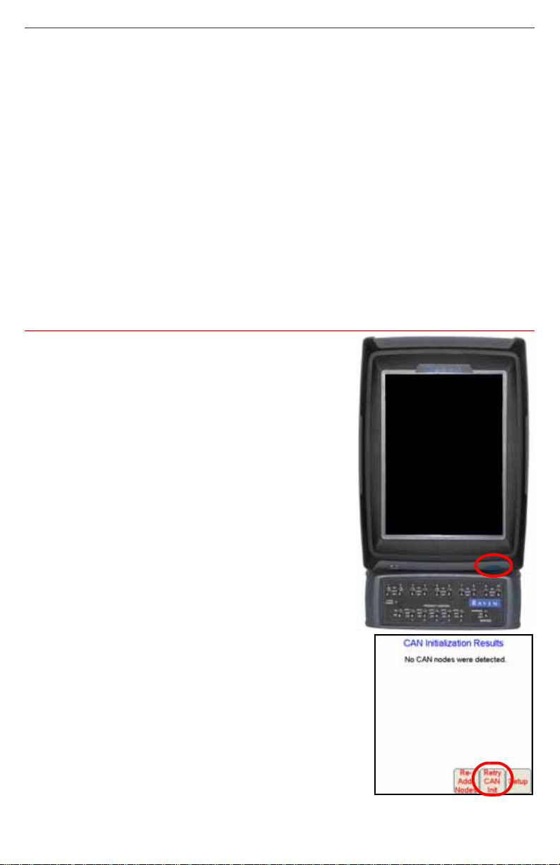
Basic Startup
1. Touch the power button to turn on the Viper Pro
field computer.
2. Allow the Viper Pro field computer to power up.
3. If the Program Selection Menu displays, touch
the OmniSeed option to begin the Viper Pro
application on the field computer.
Note: Refer to the OmniSeed Viper Pro Installation
and Operation Manual for information about
the other options available in the Program
Selection Menu.
4. Verify that the appropriate CANbus nodes or
control channels are displayed on the CAN
Initialization Results screen and touch the Start
Viper button to launch the Viper Pro precision
application management system.
If nodes or control channels do not display correctly
when the Viper Pro is powered on, touch the Retry
CAN Init button. If you still have CAN issues, see
the Viper Pro Installation and Operation Manual for
more information.