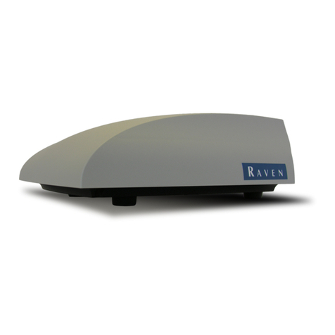
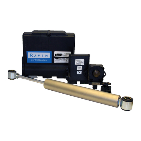
Raven SmarTrax Steering Kit User manual

SmarTrax™ Installation Manual
Case MX 180-270 Series Wheel Tractors

While every effort has been made to ensure the accuracy of this document,
Raven Industries assumes no responsibility for omissions and errors. Nor is any
liability assumed for damages resulting from the use of information contained
herein.
Raven Industries shall not be held responsible or liable for the effects of
atmospheric conditions and sunspot activity on the performance of our products.
Raven Industries cannot guarantee the accuracy, integrity, continuity, or
availability of the GPS signal from the U.S. Department of Defense/NAVSTAR
GPS satellites, the OmniSTAR correction service or the WAAS correction
service.
Raven Industries accepts no responsibility for the use of the signal for other than
the stated purpose. Raven Industries shall not be responsible or liable for
incidental or consequential damages or a loss of anticipated benefits or profits,
work stoppage or loss or impairment of data arising out of the use, or inability to
use, the SmarTrax or any of its components.
Disclaimer

Manual # 016-0190-006
1
C H A P T E R
1
INTRODUCTION
Congratulations on your purchase of the Raven SmarTrax system! This system is designed
to provide cutting-edge, hands-free steering of your machine via GPS coordinates.
The instructions in this document are to be ussed to install the Smartrax Steering Kit for the
following models of CASE Wheel Tractors:
MX180,MX200,MX220,MX240,andMX270

Case MX 180-270 Series Wheel Tractors SmarTrax Installation Manual
2
Basic Kit
Contents
Below you will see the kit contents that you should have received with this SmarTrax
kit.
Case MX 180-270 Series Wheel Tractors SmarTrax Kit Contents
ytitnauQnoitpircseDmetIrebmuNtraP
1SPS,tiK100-1810-360
1072XMesaC,dlofinaM,.dyH,tekcarB,tnemdleW015-9510-611
1edirrevO/dioneloS,ciluardyH,elbaC664-1710-511
1sgtF/WjdAraB001-51,DH,orciM,erusserP,hctiwS470-0000-224
1feileR/WSLretneCdesolC,.dyH,evlaV660-3000-433
4daeHxeH"8/7x81-61/5,tloB401-2500-113
1gnoLmm52xmm61cirteMxeH,tloB900-0700-113
4"61/5,kcoL,rehsaW910-0001-313
1noitallatsnI,launaM600-0910-610
1xartramS,noitallatsnI,launaM120-1009-610
1petStoNoD,gninraW,lebaL886-9510-140
1gnirepmaT,gninraW,lebaL986-9510-140
3F/MCIJ6-,leviwS°54,woblE,.gtF720-2100-333
4F/M/MSFRO8-,eeTnuRleviwS,retpadA,.gtF820-2100-333
4F/MCIJ6-,leviwS°09,woblE,.gtF240-2100-333
4FJ6"386-S09FF8,dyH,esoH920-0001-412
1FJ6"084-S09FF6,.dyH,esoH030-0001-412
1FJ6"086-MF6,.dyH,esoH130-0001-412

Manual # 016-0190-006
3
C H A P T E R
2
SAFETY
Important: Hydraulics are under pressure. Never attempt to
open or work on a hydraulic system with the equipment running.
Care should always be taken when first opening a system that
was previously pressurized.
When disconnecting the hydraulic hoses or when purging is required, be aware
that the hydraulic oil within the machine system may be extremely hot and under
high pressure. Caution must be exercised. Any work carried out on the hydraulic
system must be performed in accordance with the machine manufacturerer’s
approved maintenance instructions. Raven Industries recommends that appropri-
ate protective equipment be worn when working on the hydraulic system. Ob-
jects or materials that are able to bypass the machine’s hydraulic filtration system
will adversely reduce performance and possibly damage the hydraulic valves.
Do not reverse the power leads. Doing so will cause severe damage to the
equipement. Always check to make sure that the power leads are connected to
the right polarity as marked. Ensure that the power cable is the last cable to be
connected.
Hydraulic
Safety
Requirements
Electical
Safety
Requirements

Case MX 180-270 Series Wheel Tractors SmarTrax Installation Manual
4
We welcome your feedback about this manual. If you have any comments or
suggestions for improvement, please let us know by contacting our Customer
Support Center by any of the following methods:
Via phone: 1-800-243-5435
Viamail:
Raven Industries
FlowControlDivision
205 E. 6th St.
Sioux Falls, SD 57104
Via email: [email protected]
Contacting
Raven
Industries

Manual # 016-0190-006
5
C H A P T E R
3
MOUNTING THE BRACKET AND VALVE
1. The Smartrax Valve and Pressure Switch are both mounted on the
supplied mounting bracket.
2. The Steering Override Pressure Switch is connected directly to the PS
Port on the Smartrax Valve.
3. The mounting point for the Steering Assist Valve Bank and Steering
Override Pressure Switch is located on the front of the transmission
housing, above and in front of the RHS rear axle in the wheel arch, and
behind the hydraulic pump.
SteeringAssist Valve Bank mounting location
Installing
Steering Assist
Valve Bank &
Steering
Override
Pressure
Switch

Case MX 180-270 Series Wheel Tractors SmarTrax Installation Manual
6
Steering Assist Valve Bank & Pressure Switch
(NOTE: Valve in picture differs from one currently used.)
4. Mount the Smartrax Valve w/Pressure Switch attached on the mounting
bracket using the supplied bolts.
Bracket mounting area
Steering Assist Valve Bank mounted

Manual # 016-0190-006
7
C H A P T E R
4
HYDRAULICS
Steering Assist
Valve Bank
Hose Routing
Location of tractor SCU - Close-up View

Case MX 180-270 Series Wheel Tractors SmarTrax Installation Manual
8
2. Attach the tee connectors supplied to the L, R, P, and Tports of the
SCU.
The figure below shows the tractor SCU ports before installation.
Important: Take precautions to prevent any contaminates
being introduced into the tractors hydraulic system.
Helpful Hint: The L& Rtee connectors should be
positioned towards the LHS of the tractor while the P& T
connectors should be positioned to the RHS of the tractor to
provide easy installation of the hydraulic hoses.
Ports T, P, A, and B connections on SCU before install
T, P, A, and B tee connections on SCU after install

Manual # 016-0190-006
9
3. The Tank, Pressure, Left-Steer, and Right-Steer hoses (P/N
219-1000-029) supplied are to connect to their corresponding ports, T,
P, L, and Rports on the tractor SCU using the tee connectors supplied.
Supplied Tank, Pressure, Left-Steer, & Right-Steer connections to SCU
4. Pass all hoses under the SCU between the bottom of the cab and top
of the transmission housing.
5. Route the hoses rearward parallel to the existing steel hydraulic pipes
to the Smartrax Valve.
Hose routing from SCU

Case MX 180-270 Series Wheel Tractors SmarTrax Installation Manual
10
Hose routing under cab
7. The hoses are then routed along the existing steel hydraulic pipes,
secure with cable ties.
8. The hoses are then connected to the appropriate ports on the Steering
Assist Valve Bank. Pressure - “P” port; Tank - “T” port; Left - “A”
port; Right - “B” port.
Hose routing along existing pipes

Manual # 016-0190-006
11
9. Separate the original H1 hose and the H2 hose coming from the
orbital load sense which are located under and to the left of the SCU.
10. The LS-Steer hose (P/N 214-1000-031) supplied connects to the
original H1 hose, which goes to the steering orbital, while the supplied
LS-PV hose (P/N 214-1000-030) connects to the original H2 hose.
11. Once the hoses are connected, they are to be routed the same way as
the Tank, Pressure, Left-Steer, and Right-Steer.
12. The LS-Steer hose and LS-PV hose connect to their appropriate
ports, LS-Steer and LS-PV, respectively on the Steering Assist Valve
Bank.
Supplied LS-Steer and LS-PV hose connections to original H1 and H2 hoses

Case MX 180-270 Series Wheel Tractors SmarTrax Installation Manual
12

Manual # 016-0190-006
13
C H A P T E R
5
STEERING POSITION SENSOR INSTALLATION
AND CABLE CONNECTIONS
•The SPS mounts on either side of the front axle.
•One end of the SPS mounts to the outer end of the steering tie rod
by the ball joint using the supplied hose clamps and mounting tab.
•The opposite end of the SPS mounts to the bolt on the top of the
differentialhousing.
•Part of the supplied bracket can be used to make a small mounting
tab for the SPS.
•Be sure not to over extend or over compress the sensor
upon initial startup!
Mounting the
Steering Position
Sensor (SPS)

Case MX 180-270 Series Wheel Tractors SmarTrax Installation Manual
14
Cable
Connections •Connect labeled ends of the cable to the valve, pressure switch, and
SPS.
•Route Cable into the cab.
•Secure cable away from moving parts and heat sources.

Manual # 016-0190-006
15
C H A P T E R
6
START-UP PROCEDURES
After installing the SmarTrax on your machine, always follow these start-up pro-
cedures.
Make sure the Steering Position Sensor does not over-extend or over-
compress when turning the wheels.
Turn the wheels fully from side to side numerous times to remove air
from the hydraulic system.
Important: Time the wheels for a full left to right and right to
left time of approximately 5 seconds. Refer to the Universal
Kit Manual for additional instructions on this.
Adjust the pressure switch to the most responsive setting. Refer to the
Universal Kit Manual for instructions on this.

Case MX 180-270 Series Wheel Tractors SmarTrax Installation Manual
16
Notes:

Raven Industries will not assume any expense or liability for repairs
made outside our facilities without written consent. Raven Industries
is not responsible for damage to any associated equipment or
products and will not be liable for loss of profit or other special
damages. The obligation of this warranty is in lieu of all other
warranties, expressed or implied, and no person or organization is
authorized to assume any liability for Raven Industries.
Damages caused by normal wear and tear, misuse, abuse, neglect,
accident, or improper installation and maintenance are not covered
by this warranty.
What Does this Warranty Cover?
How Long is the Coverage Period?
How Can I Get Service?
What Will Raven Industries Do?
What is not Covered by this Warranty?
Bring the defective part and proof of purchase to your Raven Dealer.
If your Dealer agrees with the warranty claim, the Dealer will send the
part and proof of purchase to their distributor or to Raven Industries
for final approval.
Upon confirmation of the warranty claim, Raven Industries will, at our
discretion, repair or replace the defective part and pay for return
freight.
RAVENINDUSTRIES
Limited Warranty
This warranty covers all defects in workmanship or materials in your
Raven Applied Technology Product under normal use, maintenance,
and service.
Raven Applied Technology Products are covered by this warranty for
12 months after the date of purchase. This warranty coverage applies
only to the original owner and is nontransferable.

Notice: This document and the information provided are the property of Raven Industries, Inc. and may only be used as authorized
by Raven Industries, Inc. All rights reserved under copyright laws.
Case MX 180-270 Series Wheel Tractors
SmarTrax™ Installation Manual
(P/N 016-0190-006 Rev E 3/09)
Raven Industries Toll Free (U.S. and Canada): (800)-243-5435
Applied Technology Division or Outside the U.S. :1 605-575-0722
P.O. Box 5107 Fax: 605-331-0426
Sioux Falls, SD 57117-5107 www.ravenprecision.com
Table of contents
Other Raven Tractor Accessories manuals
Raven
Raven TC1 User manual

Raven
Raven AutoBoom Rogator 54 Series 1997+ User manual

Raven
Raven TC1 User manual

Raven
Raven SmarTrax User manual

Raven
Raven SmarTrax User manual

Raven
Raven SBGuidance Auto User manual

Raven
Raven AutoBoom User manual

Raven
Raven SmarTrax User manual

Raven
Raven SmarTrax User manual

Raven
Raven ICD Sidekick Pro User manual

Raven
Raven SmarTrax User manual

Raven
Raven SmarTrax User manual

Raven
Raven SmarTrax MD Use and care manual

Raven
Raven RS1 User manual

Raven
Raven SmarTrax MD User manual

Raven
Raven AccuBoom User manual
Raven
Raven SC1 User manual

Raven
Raven VSN User manual

Raven
Raven AccuBoom User manual
Raven
Raven SmarTrax User manual