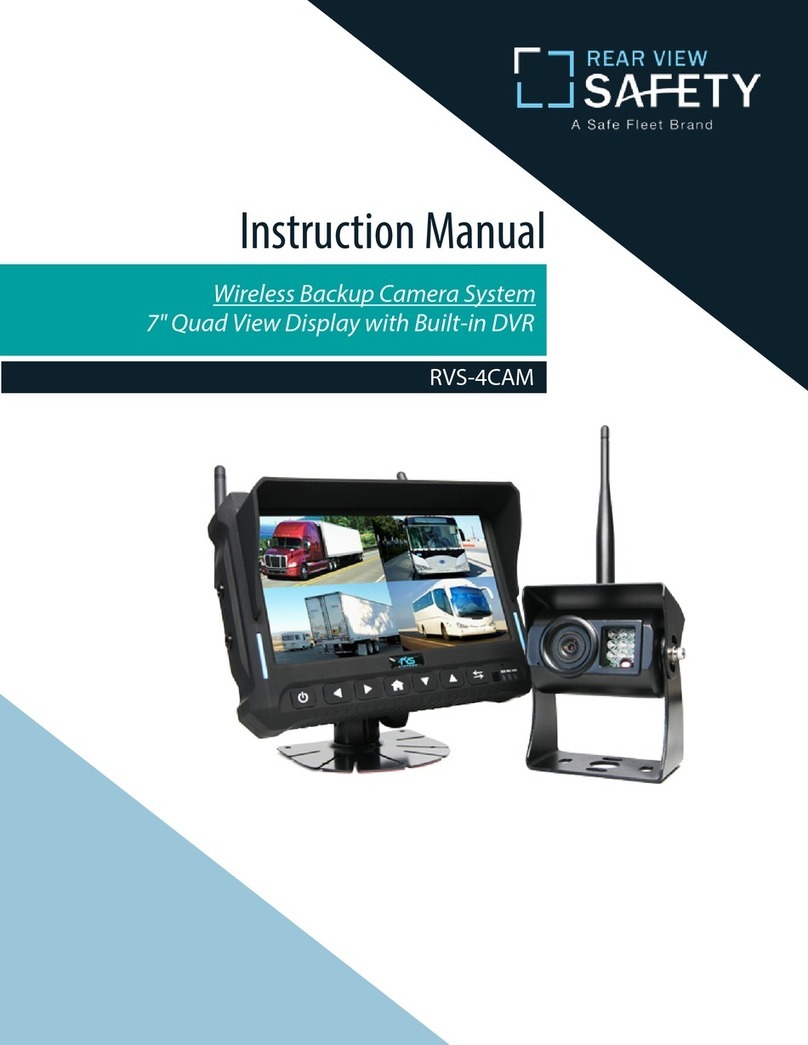
Rear view safety RVS-776718-BT User manual

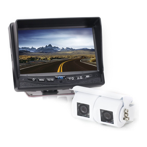
G-SERIES Backup Camera System with Bluetooth
RVS-776718-BT
Instruction Manual

Rear View Safety Reverse With Condence ™
2 3
NOTE! Please read all of the installation instructions
carefully before installing the product. Improper
installation will void manufacturer’s warranty.
Congratulations on purchasing a Rear View Backup
Camera System!
With this manual you will be able to properly install and
operate the unit.
The Backup Camera System is intended to be installed as a
supplement aid to your standard rear view mirror that already exists
in your vehicle. The Backup Camera System should not be used as a
substitute for the standard rear view mirror or for any other mirror
that exists in your vehicle.
In some jurisdictions, it is unlawful for a person to drive a
motor vehicle equipped with aTV viewer or screen located forward of
the back of the driver’s seat or in any location that is visible, directly
or indirectly, to the driver while operating the vehicle.
Introduction...............................03
SafetyInformation..........................04-06
Before Beginning Installation. . . . . . . . . . . . . . . . . . . . . . . 07
InstallationGuide.......................... 08-09
InstallationandWire.........................10-11
MonitorSpecications..........................12
HowToWire+Splicing.........................13
CameraSpecication...........................14
CameraInstallation...........................15
GridLines...............................16
AdjustableGridLine...........................17
BluetoothConnection........................18-19
MonitorBrightness............................20
Troubleshooting.............................21
TABLE OF CONTENTS
INTRODUCTION

Rear View Safety Reverse With Condence ™
4 5
Please read the entire manual and follow the instructions and
warnings carefully. Failure to do so can cause serious damage and/or
injury, including loss of life. Be sure to obey all applicable local
trac and motor vehicle regulations as it pertains to this product.
Improper installation will void manufacturer’s warranty.
•The Rear View Camera System is
designed to help the driver safe-
ly detect people and/or objects
helping to avoid damage or injury.
However, you the driver, must use it
properly. Use of this system is not a
substitute for safe, proper or legal
driving.
•Never back up while looking at the
monitor alone. You should always
check behind and around the vehi-
cle when backing up, in the same
way as you would if the vehicle did
not have the Rear View Camera
System.Ifyoubackupwhile looking
only at the monitor, you may cause
damage or injury. Always back up
slowly.
•The Rear View Camera System is
not intended for use during exten-
sive back-up maneuvers or backing
into cross trac or pedestrian walk-
ways.
•Please, always remember, the area
displayed by the Rear View Camera
Systemislimited.It doesnot display
the entire panorama that is behind
you.
USAGE:
•Electric shock or product
malfunction may occur if this
product is installed
incorrectly.
•Use this product within
the voltage range specied. Failure
to do so can cause
electronic shock or product
malfunction.
•Take special care when
cleaning the monitor.
•Make sure to rmly ax the prod-
uct before use.
•If smoke or a burning smell
is detected, disconnect the
system immediately.
•Where the power cable may touch
a metal case, cover the cable with
friction tape. A short circuit
or disconnected wire may cause a
re.
•While installing the Rear View
System be careful with the wire
positioning in order to avoid wire
damage.
•The RearView System should only
be used when the vehicle is in
reverse.
•Do not watch movies or
operate the monitor while driving;
as it may cause an
accident.
•Do not install the monitor
where it may obstruct drivers
view or obstruct an air bag
device.
•Dropping the unit may cause
possible mechanical failure.
INSTALLATION:
SAFETY INFORMATION
SAFETY INFORMATION
Rear View Safety Reverse With Condence ™
6 7
IN NO EVENT SHALL SELLER OR MANUFACTURER BE
LIABLE FOR ANY DIRECT OR CONSEQUENTIAL DAMAGES OF
ANY NATURE, OR LOSSES OR EXPENSES RESULTING FROM
ANY DEFECTIVE PRODUCT OR THE USE OF ANY PRODUCT.
A Safe Fleet Brand
Before drilling please check that no cable or wiring is on the other side
of the wall. Please clamp all wires securely to reduce the possibility
of them being damaged while vehicle is in use. Keep all cables away
from hot or moving parts and electrical noisy components.
We recommend doing a benchmark test before installation
to insure that all components are working properly.
Step 1: Choose the monitor and camera locations.
Step 2: Install all cables in vehicle, when necessary a 0.8 (20mm)
hole should be drilled for passing camera cable through vehicles
walls. Install split grommets where applicable.
Step 3: Once all cables and wiring have been properly routed, perform
a system function test by temporarily connecting the system. If the
system seems to not be operating properly see troubleshooting (page
21).
SAFETY INFORMATION
BEFORE YOU BEGIN

Rear View Safety Reverse With Condence ™
8 9
Replacement Monitor
The mirror monitor replaces the existing car mirror. Carefully remove
the mirror o the“pin”. Slide the replacement mirror on to the pin and
secure it with the screw provided (already in the screw hole).Dier-
ent cars have dierent brackets. Depending on your vehicle make and
manufacturer. There are many methods to remove the original rear-
view mirror, however, please don’t force the mirror o the bracket.
The manufacturer will not be responsible for damage caused to your
car by wrong installation of the mirror. Figure 1.1
Clip-On Monitor
1. The Mirror Monitor attaches to the existing rear view mirror in
vehicle with the pressurized clips on the back of the monitor.
2. Attach monitor to existing mirror, and adjust mounting angle to
allow optimum driver viewing comfort.
Camera & Cable
Be sure to position the cable properly. The aviation camera cable uses
aircraft grade connectors which means the camera cable can be ex-
posed to all weather elements. Do not run the cable over sharp edges,
do not kink the cable and keep away from HOT and rotating parts.
Fasten all cables and secure all excess cable. Connect camera to the
camera extension cable which runs inside the vehicle. Figure 1.2
Wiring
After connecting the camera to the“camera cable”the camera should
be plugged into AV2 input. Connect the RED 12V power wire to an igni-
tion power source and the BLACK 12V ground wire to a chassis ground.
The GREEN wire is the REVERSE trigger wire. Connect this wire to the
vehicle’s backup light circuit to activate the rear-view image whenever
the vehicle shifts into reverse. To connect a second camera, connect it
to AV1 input. It can be turned on by pressing the power button on the
monitor. Figure 2.1, Figure 2.2
Precautions for use of Mirror Monitor
I. The Mirror Monitor is made of glass. Do not subject it to a
mechanical shock by dropping it from a high place, etc.
II. Do not apply excessive force to the monitor surface or the
adjoining areas since this may cause the color tone to vary.
III. Clean with a soft dry cloth and/or Windex only.
IV. Do not attempt to disassemble the mirror monitor.
Safety
• Before drilling, be sure no cable or wire is on the other side.
• Feed as much cable as possible into vehicle & clamp securely.
This reduces the possibility of cable being hooked or snagged.
INSTALLATION GUIDE
INSTALLATION GUIDE + TIPS

Rear View Safety Reverse With Condence ™
10 11
INSTALLATION AND WIRE
FIGURE 2.2
FIGURE 1.1
FIGURE 1.2

Rear View Safety Reverse With Condence ™
12 13
MONITOR SPECIFICATIONS
HOW TO WIRE + SPLICING
10.25”
3”
About Our Monitor
SPECIFICATIONS:
Screen Size:
Display Screen:
Display Resolution:
Aspect Ratio:
Color Depth:
Pixel Pitch (mm)
Power Consumption:
Working Voltage:
Video Input:
Signal System:
4.3”
TFT-LCD
400(H)x272(V)
16:9
16.7M dithering
0.219x0.219
8W
DC 9V-32V
NTFS/PAL Video input
PAL/Auto/NTSC
1. RED- Power (+)
2. YELLOW- Video
3. GREEN- Mirror / Normal Imaging
4. WHITE- Audio
5. BLACK- Ground (-)
FIGURE 2.1

Rear View Safety Reverse With Condence ™
14 15
CAMERA SPECIFICATIONS
CAMERA INSTALLATION
About Camera
SPECIFICATIONS:
Camera Installation
position
170º
viewangle
installation
Mounting Position

Rear View Safety Reverse With Condence ™
16 17
Generally, to help drivers estimate the distance from obstacles, there are
three lines for reference- red, yellow, and green. Those three lines are dis-
played on the monitor when car is reversing. The green line is 3M from the
back of the car and the yellow line is 6.5ft. The distant red line is 1M from
the backside of car while the close red line is 0.4M. Both reference lines on
the left and right should leave 0.2M space from the car.
The accuracy of the grid-lines can vary based on how you angle your cam-
era. Therefore to compensate for inaccurancies, you can adjust the grid-
lines to your camera angle.
Accuracy
Grid Lines
Longpressthesettingsbutton toenterinto“grid-lineadjustment”mode.
The upper half of the remote is used to adjust the left grid line while the
bottom half of the remote is used to adjust the right one. The up, down,
left and right buttons are used to adjust the location of grid lines. The
clockwise rotation contra rotation buttons are used to adjust the angle
of grid lines. It is easy to operate and calibrate.
GRID LINES
ADJUSTABLE GRID LINE

Rear View Safety Reverse With Condence ™
18 19
BLUETOOTH CONNECTION
Start Up
The rst time you use the rear view mirror, Bluetooth will automati-
cally turn on when the car is started.Wait for 1 minute to connect your
phone with the mirror. During this rst minute, the mirror will search
for the last paired phone.
Connecting To A New Phone
Once a minute has passed after the system turns on, connect your mo-
bile phone or other device to the rear view mirror.
BLUETOOTH CONNECTION
Successfully Connected
After the password has been set, a Bluetooth icon will appear on the
monitor. This indicates a sucessful connection. After 5 seconds, the
monitor will automatically shut o and the Bluetooth system will
enter a standby mode.
Manual Bluetooth Connection
If your phone is not connected to the rear view mirror and the screen
is o, long press the center button to manually reconnect Bluetooth.

Rear View Safety Reverse With Condence ™
20 21
MONITOR BRIGHTNESS
Backup Camera Display And Manual Brightness Adjustment
After installation, place the vehicle in reverse and the backup camera
image will automatically display on the monitor. Once this image is
displayed, you can manually adjust the monitors’ brightness by press-
ing the center button. The brightness can be adjusted from 10 to 100.
The OSD menu will disappear after 5 seconds of inactivity.
Auto Brightness Adjustment
Your system will automatically adjust monitor brightness based on
ambient light. The monitor will be comfortably visable in both bright
sunshine and the darkness of night.
•Do a hard reset, unplug all cables
and power cables, leave out for 1
minute, and re-connect them
•Check to ensure that the
connection to the camera is tight
•Verify camera cable is plugged into
port labeled Backup Camera
•Verify that the green positive
trigger on power harness is set to
power 12v+
•Verify camera is on correct camera
input
•Verify cable is connected to
monitor
•Verify camera is connected to
cable
•Connect known working camera
and cable to monitor
•Verify green trigger is receiving
power
No Image On Screen
TROUBLESHOOTING
Table of contents
Other Rear view safety Automobile Electronic manuals

Rear view safety
Rear view safety RVS-776718-BB User manual

Rear view safety
Rear view safety RVS-115 User manual

Rear view safety
Rear view safety RVS-813613-NM User manual

Rear view safety
Rear view safety RVS-8129900Q User manual

Rear view safety
Rear view safety RVS-25W User manual

Rear view safety
Rear view safety Go Vue RVS-020770 User manual

Rear view safety
Rear view safety RVS-5350-W User manual

Rear view safety
Rear view safety RVS-8106131N User manual

Rear view safety
Rear view safety RVS-111 User manual

Rear view safety
Rear view safety RVS-020813 User manual