Camargue®
4
MONTAGE D’UN
PANNEAU LINIUS POUR
LA CAMARGUE
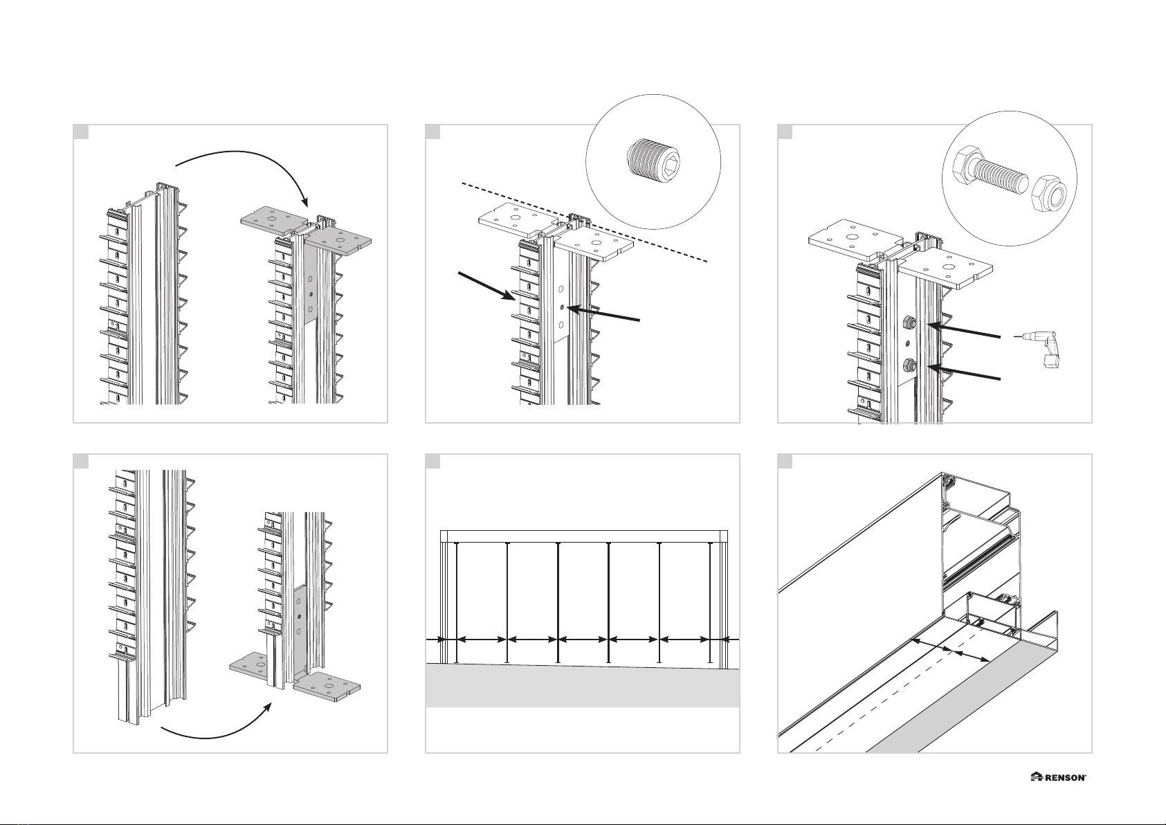
1. Montage panneau Linius
sur toute la hauteur
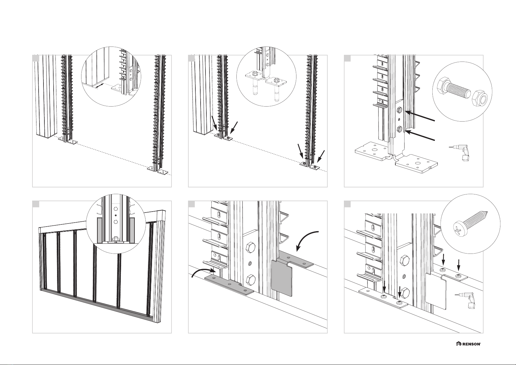
• Prenez les profils porteurs verticaux. Glis-
sez les 2 équerres de montage sur le côté
supérieur du profil porteur. A
• Veillez à ce que l’extrémité des équerres
de montage soit bien alignée à l’extrémité
du profil porteur.
Fixez les vis de montage M6 x 8 mm
dans l’ouverture centrale des équerres de
montage. B
• Forez des trous de Ø 8,5 mm au-dessus et
au-dessous de la vis de montage dans le
profil porteur.
Placez les boulons M8 x 25 et les écrous
et fixez-les. C
• Répétez les étapes précédentes A+B pour
le côté inférieur des profils porteurs. D
• Indiquez l’emplacement des profils
porteurs sur la partie inférieure du profil
cadre supérieur (Span ou Pivot).
Le premier et le dernier profil porteur doit
se trouver à 200 mm de la partie intérieure
de la colonne. Les autres profils porteurs
sont répartis sur la largeur. E
• Marquez le milieu du profil cadre supé-
rieur.
Attention : il ne faut pas tenir compte de
la gouttière. Il faut mesurer 75 mm à partir
du côté extérieur. F
MOUNTING A LINIUS
WALL IN CAMARGUE
1. Montage full height Linius
wall
• Get the vertical support profiles. Slide
2 assembly brackets into the top of the
support profile. A
• Ensure that the ends of the assembly
brackets are perfectly even with the outside
of the support profile.
Tighten the supplied setscrews M6 x 8 mm
in the centremost opening of the assembly
brackets. B
• Drill Ø8.5-mm holes into the support profile
just above and below the setscrew.
Insert the supplied bolts M8 x 25 and nuts,
tighten these. C
• Repeat the steps above A+B for the bottoms
of the support profiles. D
• Mark off the location of the support profiles
on the bottom of the top beam (Span or
Pivot).
Here is where the first and last support
profile will be placed at 200 mm from the
inside of the column. The other support
profiles should be spread out evenly. E
• Also mark off the centre of the top beam.
Attention: do not take the gutter on the
Pivot side into account. So start measuring
as from 75 mm from the outside. F
MONTAGE DER LINIUS-
WAND BEI CAMARGUE
1. Montage Linius-Wand
vollständige Höhe
• Nehmen Sie die vertikalen Trägerprofile.
Schieben Sie 2 Montagebügel an die
Oberseite des Trägerprofils. A
• Sorgen Sie dafür, dass das Ende der
Montagebügel und die Außenseite des
Trägerprofils gleich ausgerichtet sind.
Schrauben Sie die mitgelieferten M6 x 8
mm Stellschrauben in der mittleren Öffnung
der Montagebügel fest. B
• Bohren Sie die Löcher über und unter der
Stellschraube mit Ø 8,5 mm in das Träger-
profil durch.
Setzen Sie die mitgelieferten M8 x 25
Schraubbolzen und Muttern ein und
schrauben Sie diese fest. C
• Wiederholen Sie die vorhergegangenen
Schritte A+B für die Unterseite der Träger-
profile. D
• Zeichnen Sie die Position der Trägerpro-
file an der Unterseite des oberen Balkens
(Span- oder Pivot-Seite) ein.
Dabei befinden sich das erste und das
letzte Trägerprofil in einem Abstand von
200 mm von der Innenseite des Pfostens.
Die anderen Trägerprofile werden gleich-
mäßig verteilt. E
• Zeichnen Sie auch die Mitte auf dem
oberen Balken ein.
Achtung: an der Pivot-Seite die Rinne
nicht mitrechnen. Also 75 mm von der
Außenseite aus messen. F
MONTAGE LINIUS WAND
BIJ CAMARGUE
1. Montage Linius wand op
volledige hoogte
• Neem de vertikale draagprofielen. Schuif
2 montagebeugels aan de bovenzijde van
het draagprofiel. A
• Zorg dat het uiteinde van de montagebeu-
gels mooi gelijk loopt met de buitenzijde
van het draagprofiel.
Draai de meegeleverde stelschroeven M6
x 8 mm vast in de middelste opening van
de montagebeugels. B
• Boor de gaten boven en onder de stel-
schroef door in het draagprofiel met
Ø8,5mm.
Plaats de meegeleverde bouten M8 x 25
en moeren en schroef ze vast. C
• Herhaal de vorige stappen A+B voor de
onderzijde van de draagprofielen. D
• Teken de plaats van de draagprofielen af
op de onderzijde van de bovenbalk (Span
of Pivot).
Hierbij komt het eerste en laatste draagpro-
fiel op 200 mm van de binnenzijde van de
kolom. De overige draagprofielen worden
gelijk verdeeld. E
• Teken ook het midden op de bovenbalk af.
Opgelet: op pivotzijde de goot niet
meerekenen. Dus 75 mm vanaf de buiten-
kant meten. F