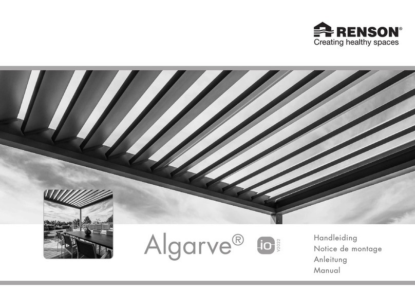
Renson Aero io User manual

Handleiding
Notice de montage
Anleitung
Manual
Aero®

2
Aero®
INDEX
1. Important safety and assembly
instructions 5
2. Positioning frame profiles 8
3. Mounting the frame 10
4. Mounting the coupling profile 12
5. Checking the diagonals 14
6. Position the cover plates 16
7. Sealing inside corner joint 20
8. Mounting the blades for Pivot
according to the blade pitch 24
9. Mounting the blades for pivot on
the mm 28
10. Mounting the motor 36
11. Connecting the control box +
setting control for the louvred roof 38
11.1 Configuring the end points
automatically 40
11.2 Activation of the snow and
frost position 44
12. Return to the default settings for the
motor of the louvred roof 46
13. Mounting the Lineo LED blades
(optional) 48
14. Finishing 50
15. Mounting of Protecto 52
15.1 Fitting the sliding pieces on
the sealing profile 52
15.2 Applying the protective tape
to the blade 54
15.3 Fitting the sealing profile 56
16. Fitting an UpDown light on the
pivot side (optional) 58
17. Mounting the UpDown light on the
span side S2 (motor side) 62
INHALTSANGABE
1. Wichtige Sicherheits- und
Montagehinweise 5
2. Positionierung der Rahmenprofile 8
3. Einbau des Rahmens 10
4. Montage des Kopplungsbalkens 12
5. Überprüfung der Diagonalen 14
6. Platzierung der Abdeckkappen 16
7. Abdichten der Innenseite der
Eckverbindung 20
8. Montage der Lamellen für Pivot
gemäß pro Lamellenschritt 24
9. Montage der lamellen für pivot
auf den mm 28
10. Montage des motors 36
11. Anschliessen des Steuerkastens
und einstellen der Bedienung für
Lamellendach 38
11.1 Automatisches Einstellen der
Endpunkte 40
11.2 Aktivierung der Schnee- und
Frostposition 44
12. Wiederherstellung der Werks-
einstellungen des Motors für
Lamellendach 46
13. Montage der Lineo LED-Lamellen
(optional) 48
14. Endbearbeitung 50
15. Montage von Protecto 52
15.1 Gleitblöcke einsetzen auf dem
Abdeckprofil 52
15.2 Schutztape an der Lamelle
anbringen 54
15.3 Montage des Abdeckprofils 56
16. Montage von UpDown Light an der
Pivot-Seite (optional) 58
17. Montage von UpDown Light an
Spanseite S2 (Motorseite) 62
TABLE DES MATIÈRES
1. Instructions importantes de sécurité
et de montage 5
2. Positionnement des profils cadre 8
3. Montage du cadre 10
4. Montage de la poutre de couplage 12
5. Contrôle des diagonales 14
6. Montage des plaques d’obturation 16
7. Étanchement du côté intérieur des
jonctions d’angle 20
8. Montage des lames pour pivot
selon le pas de lame 24
9. Montage des lames pour pivot
au mm près 28
10. Montage du moteur 36
11. Raccordement du boîtier de
commande + programmation de la
commande du toiture en lames 38
11.1 Réglage automatique des fins
de course 40
11.2 Activation de la position neige
et gel 44
12. Revenir au réglage usine pour le
moteur du toiture en lames 46
13. Montage des lames Lineo LED
(option) 48
14. Finition 50
15. Montage de Protecto 52
15.1 Pose des blocs de coulissement
sur le profil d’obturation 52
15.2 Placement de la bande de
protection sur la lame 54
15.3 Montage du profil d’obturation 56
16. Montage de l’éclairage UpDown
au côté pivot (option) 58
17. Montage de l’éclairage UpDown
au côté span S2 (côté moteur) 62
INHOUDSTAFEL
1. Belangrijke veiligheids- en montage-
instructies 5
2. Positioneren kaderprofielen 8
3. Montage van het kader 10
4. Koppelbalk monteren 12
5. Controle diagonalen 14
6. Plaatsen afdekkappen 16
7. Afdichten binnenkant hoekverbinding 20
8. Montage van de lamellen voor pivot
volgens stap van de lamel 24
9. Montage van de lamellen voor pivot
per mm 28
10. Montage van de motor 36
11. Aansluiten stuurkast + instellen
bediening voor lamellendak 38
11.1 Automatisch afstellen van de
eindpunten 40
11.2 Activatie van de sneeuw- en
vorstpositie 44
12. Terugkeren naar de fabrieksinstellingen
voor de motor van het lamellendak 46
13. Monteren van de Lineo LED lamellen
(optie) 48
14. Afwerking 50
15. Montage van Protecto 52
15.1 Plaatsen van de glijblokjes op
het afsluitprofiel 52
15.2 Aanbrengen van de
beschermingstape op de lamel 54
15.3 Monteren van het afsluitprofiel 56
16. Plaatsing UpDown light aan
pivotzijde (optie) 58
17. Plaatsing UpDown light aan
spanzijde S2 (motorzijde) 62

3
Aero®
18. Mounting the UpDown light on the
span side S1 (non-motor side) 66
19. Cabling of the LED control 70
19.1 Cabling of the LED blade -
White (Lineo Led) 72
19.2 Cabling of the UpDown LED -
White 74
19.3 Cabling of the UpDown LED -
RGB 76
20. Configuring the LED lighting 78
20.1 Setting UpDown and/or
Lineo LED lighting with only
white LED’s 78
20.2 Setting UpDown LED lighting
RGB 80
20.3 Setting the Situo Variation io
remote control to user
MODE 2 82
20.4 Returning the LED lighting to
factory settings 84
21. Mounting Heat/Sound Beam 86
21.1 Mounting suspension bracket
for a beam 86
21.2 Hanging the beam 88
21.3 Connecting heating element
cables 92
21.4 Set up the Heat using the
Situo io hand-held remote 96
21.5 Connecting speaker cables 98
21.6 Connecting amplifier/
Bluetooth cables 100
21.7 Connecting multiple amplifiers
to each other 106
21.8 Finishing 110
21.9 Final check 110
22. Mounting the rain sensor 112
23. Installing the wind sensor 114
18. Montage von UpDown Light an
Spanseite S1 (nicht-Motorseite) 66
19. Verkabelung von der LED-Steuerung 70
19.1 Verkabelung der LED-Lamelle -
Weiß (Lineo Led) 72
19.2 Verkabelung der UpDown LED -
Weiß 74
19.3 Verkabelung der UpDown LED -
RGB 76
20. Einstellen der LED-Beleuchtung 78
20.1 Einstellen UpDown und/oder
Lineo LED-Beleuchtung mit nur
weißen LEDs 78
20.2 Einstellen UpDown
LED-Beleuchtung RGB 80
20.3 Situo Variation io-Handsender
in Gebrauchsmodus2 setzen 82
20.4 Zurücksetzen der LED-Beleuchtung
auf die Werkseinstellungen 84
21. Montage Heat/Sound Beam 86
21.1 Montage der Aufhängebügel
des Beam 86
21.2 Das Aufhängen des Beam 88
21.3 Anschluss der Verkabelung
des Heizelements 92
21.4 Einstellen des Heat mit den
Situo io-Handsender 96
21.5 Anschließen der Lautsprecher-
verkabelung 98
21.6 Anschluss der Verkabelung
des Verstärkers/Bluetooth 100
21.7 Verbindung mehrerer
Verstärker miteinander 106
21.8 Endbearbeitung 110
21.9 Endkontrolle 110
22. Montage des Regensensors 112
23. Montage des Windsensors 114
18. Montage de l’éclairage UpDown
au côté span S1 (côté opposé au
moteur) 66
19. Câblage de la commande LED 70
19.1 Câblage de la lame LED -
Blanc (Lineo Led) 72
19.2 Câblage de l’UpDown LED -
Blanc 74
19.3 Câblage de l’UpDown LED -
RVB 76
20. Réglage de l’éclairage LED 78
20.1 Réglage de l’éclairage
UpDown et/ou Lineo LED avec
seulement des LED blanches 78
20.2 Réglage de l’éclairage
UpDown LED RVB 80
20.3 Placer la télécommande Situo
Variation io en MODE 2 82
20.4 Revenir aux programmations
usine pour l’éclairage LED 84
21. Montage Heat/Sound Beam 86
21.1 Montage des équerres de
suspension de la poutre 86
21.2 Suspendre la poutre beam 88
21.3 Raccordement du câblage de
l’élément de chauffage 92
21.4 Réglage de l’élément de
chauffage par la télécommande
Situo io 96
21.5 Raccordement du câblage des
haut-parleurs 98
21.6 Raccordement du câblage de
l’amplificateur/Bluetooth 100
21.7 Relier plusieurs amplificateurs
mutuellement 106
21.8 Finition 110
21.9 Contrôle final 110
22. Montage du capteur de pluie 112
23. Montage du capteur de vent 114
18. Plaatsing UpDown light aan
spanzijde S1 (niet-motorzijde) 66
19. Bekabeling van de LED-sturing 70
19.1 Bekabeling van de LED lamel -
Wit (Lineo Led) 72
19.2 Bekabeling van de UpDown
LED - Wit 74
19.3 Bekabeling van de UpDown
LED - RGB 76
20. Instellen LED verlichting 78
20.1 Instellen UpDown en/of Lineo
LED verlichting met enkel witte
LED’s 78
20.2 Instellen UpDown LED
verlichting RGB 80
20.3 Situo Variation io handzender
in gebruiksMODUS 2 plaatsen 82
20.4 Terugkeren naar de fabrieks-
instellingen voor de LED
verlichting 84
21. Montage Heat/Sound Beam 86
21.1 Montage ophangbeugels 86
21.2 Ophangen van de beam 88
21.3 Aansluiting bekabeling van
het verwarmingselement 92
21.4 Instellen van de Heat via
Situo io handzender 96
21.5 Aansluiten bekabeling
speakers 98
21.6 Aansluiting bekabeling
versterker/Bluetooth 100
21.7 Meerdere versterkers
onderling verbinden 106
21.8 Afwerking 110
21.9 Eindcontrole 110
22. Montage van de regensensor 112
23. Montage van de windsensor 114

4
Aero®
RENSON®AERO®
First read this manual carefully before you
begin. The installation of the RENSON®
Aero®should be done by a specialist.
RENSON®reserves the right to make tech-
nical changes to its products without prior
notice.
RENSON®AERO®
Lesen Sie diese Gebrauchsanweisung auf-
merksam durch, bevor Sie mit der Montage
beginnen. Die Montage von RENSON®
Aero®muss durch einen Fachmann erfolgen.
RENSON®behält sich das Recht vor, ohne
vorherige Mitteilung technische Änderungen
seiner Produkte vorzunehmen.
RENSON®AERO®
Lisez attentivement ce manuel avant de
commencer. L’installation de la Aero®de
RENSON®doit être effectuée par un profes-
sionnel.
RENSON®se réserve le droit d’apporter des
modifications techniques à ses produits sans
avis préalable.
RENSON®AERO®
Lees deze handleiding eerst aandachtig
eer u van start gaat. Het plaatsen van de
RENSON®Aero®dient te gebeuren door een
vakman.
RENSON®behoudt zich het recht voor om
zonder voorafgaande kennisgeving techni-
sche wijzigingen aan haar producten aan te
brengen.

5
Aero®
1.
IMPORTANT SAFETY
AND ASSEMBLY
INSTRUCTIONS
Opening the packaging
• The system is well packed to protect it
during storage and transport.
• Always store in a dry place at normal
temperature.
• Transport and handle the system carefully.
• Check the packaging for signs of major
damage.
• Open the packaging carefully.
• If using sharp objects, be careful not to
damage the paint.
• Remove the system carefully from the pack-
aging.
Installing the system
• See installation instructions. Aero®must be
installed as described in the installation
manual.
• Before you begin the assembly, check
whether all parts are undamaged and all
materials are present.
• Ensure that you have understood the
instruction manual before you start the
assembly.
• It is recommended that the assembly is
done by at least 2 persons using an assem-
bly lift.
• We recommend that at least two people
assemble the product. We also recommend
using a material lift.
• Installers must be both mentally and physi-
cally fit to carry out the installation; they
must also always abide by all safety regu-
lations.
• Check all attachment walls for gas pipes,
water pipes or electrical wiring to prevent
damage.
• Keep children, pets and other unauthorised
personnel at a distance!
1.
WICHTIGE
SICHERHEITS- UND
MONTAGEHINWEISE
Öffnen der Verpackung
• Zum Schutz während der Lagerung und
während des Transports wurde das System
mit einer stabilen Verpackung versehen.
• Die Lagerung muss stets in trockener Umge-
bung und unter normalen Temperaturbedin-
gungen erfolgen.
• Transport und Handhabung müssen mit der
nötigen Sorgfalt erfolgen.
• Kontrollieren Sie die Verpackung auf even-
tuelle grobe Beschädigungen.
• Öffnen Sie die Verpackung mit der nötigen
Vorsicht.
• Achten Sie bei Benutzung scharfer Gegen-
stände darauf, den Lack nicht zu beschä-
digen.
• Entnehmen Sie das System mit der nötigen
Umsicht aus der Verpackung.
Anbringung des Systems
• Siehe Montageanweisungen. Aero®muss
wie in der Montageanleitung beschrieben
installiert werden.
• Kontrollieren Sie vor Beginn der Montage,
ob alle Teile unbeschädigt und alle Materi-
alien vorhanden sind.
• Sorgen Sie dafür, dass Sie die Gebrauchs-
anweisung verstanden haben, bevor Sie
mit der Montage beginnen.
• Es wird empfohlen, die Montage mit
mindestens 2 Personen und einem Monta-
gelift durchzuführen.
• Die Installateure müssen sowohl mental
als auch körperlich in der Lage sein, die
Montage durchzuführen. Sie müssen jeder-
zeit alle Sicherheitsvorschriften einhalten.
• Überprüfen Sie alle Befestigungswände
auf Gas-, Wasser- oder Stromleitungen, um
Beschädigungen zu vermeiden.
• Halten Sie Kinder, Haustiere und andere
unbefugte Personen auf Distanz!
1. INSTRUCTIONS IMPOR-
TANTES DE SÉCURITÉ
ET DE MONTAGE
Ouverture de l’emballage
• Le système est protégé par un embal-
lage robuste afin d’éviter des dommages
pendant le stockage et le transport.
• Le stockage se fait toujours dans des condi-
tions sèches et de température normale.
• Le transport et la manipulation doivent être
effectués avec le plus grand soin.
• Vérifiez s’il n’y a pas de dégâts importants
à l’emballage.
• Ouvrez l’emballage prudemment.
• N’endommagez pas la peinture en
employant des objets tranchants.
• Sortez le système prudemment de l’embal-
lage.
Installation du système
• Voir les instructions de pose ci-jointes.
Aero®doit être installée conformément au
manuel d’installation.
• Contrôlez avant de commencer le montage
que toutes les pièces sont intactes et que
tous les matériaux sont présents.
• Vérifiez que vous comprenez le manuel
avant de commencer le montage.
• Le montage doit être effectué par au moins
2 personnes et à l’aide d’un élévateur.
• Les installateurs doivent être aptes physi-
quement et mentalement à exécuter
l’installation, ils doivent toujours respecter
les conditions de sécurité.
• Vérifiez la présence éventuelle sur les
parois de fixation de conduits de gaz,
électricité ou eau afin d’éviter tout endom-
magement.
• Tenez les enfants, animaux ou autres
personnes non autorisées à distance !
1. BELANGRIJKE VEILIG-
HEIDS- EN MONTAGE-
INSTRUCTIES
Openen van de verpakking
• Het systeem werd ter bescherming tijdens
opslag en transport voorzien van een
stevige verpakking.
• Opslag dient steeds onder droge omstan-
digheden te gebeuren en onder normale
temperatuurscondities.
• Transport en handeling dient met de
nodige zorg te gebeuren.
• Bekijk of er geen grove beschadiging aan
de verpakking op te merken valt.
• Open de verpakking met de nodige voor-
zichtigheid.
• Bij gebruik van scherpe voorwerpen uitkij-
ken om de lak niet te beschadigen.
• Haal het systeem met de nodige omzichtig-
heid uit de verpakking.
Plaatsing van het systeem
• Zie de meegeleverde plaatsingsinstructies
voor de details omtrent de plaatsing van
Aero®.
• Controleer vooraleer u begint aan de
montage of alle onderdelen onbeschadigd
zijn en alle materialen aanwezig zijn. Het
ontbreken van onderdelen, dan wel de
omstandigheid dat bepaalde onderdelen
beschadigd zijn, dient steeds onmiddellijk
na ontdekking te worden gemeld aan uw
verkoper. Aero®mag niet geïnstalleerd
worden indien niet alle onderdelen aanwe-
zig zijn of wanneer onderdelen bescha-
digd zijn.
• Zorg ervoor dat u de handleiding begre-
pen heeft vooraleer u start met de montage.
• Montage aanbevolen met minimum 2
personen en montagelift.
• Installateurs moeten zowel mentaal als
fysiek geschikt zijn om de installatie uit te
voeren, ze dienen ook steeds alle veilig-
heidsvoorschriften te respecteren.

6
Aero®
1. Important safety and
assembly instructions
(continued1)
• Ensure that no person or obstacle can inter-
rupt a moving screen covering. Moving
parts (such as a screen covering) could
pose a danger.
• Do not place fingers in a lateral guide
while the screen covering is moving.
• Faulty installations or irregularities in the
installation could have serious consequen-
ces when using the product.
• Only use the components delivered by the
RENSON®company with your product;
otherwise, the guarantee terms and condi-
tions could be nullified.
• Any change to the product, by the custo-
mer or installer, can result in the warranty
lapsing.
• All fixing elements for walls/floors are
not included. These must be stipulated by
the installer because these depend on the
material to which it will be affixed.
• The wall, floor and fixing elements must
be suitable to bear this terrace covering
and to have it affixed to them under the
weather conditions that the terrace cove-
ring is meant to withstand (see “wind
class”). Contact a stability engineer in case
of doubt/if necessary.
• Work safely and always wear the required
personal protective equipment.
• Dispose of the packaging waste (e.g.
sorting) according to local regulations.
• The sequence of installation can vary
depending on the situation on site.
• Nothing may be attached either to the
columns or to the lateral guides of the roof
since this can be harmful to the proper
operation of the product.
• Always take care when opening the cap
on the box.
• Check the cables for damage at regular
intervals.
• Be sure the structure is grounded properly.
1. Wichtige Sicherheits-
und Montagehinweise
(Fortsetzung1)
• Kontrollieren Sie, ob Personen oder Hinder-
nisse eine sich bewegende Markise nicht
unterbrechen können. Bewegliche Teile
(wie eine Markise) können eine Gefahr
darstellen.
• Stecken Sie nie einen Finger in eine Seiten-
führung, wenn sich die Markise bewegt.
• Eine verkehrte oder unsachgemäße Instal-
lation kann gravierende Folgen für den
Gebrauch des Produkts haben.
• Verwenden Sie nur die mitgelieferten Teile
der Firma RENSON®. Andernfalls verfallen
die Garantieansprüche.
• Jede vom Kunden oder vom Installateur
vorgenommene Änderung am Produkt
kann den Ausschluss der Garantie zur
Folge haben.
• Befestigungsmittel für Mauer, Wand oder
Boden sind nicht im Lieferumfang enthal-
ten. Diese muss der Installateur selbst
auswählen, da sie von der Art des Unter-
grunds abhängen.
• Die Wand, der Boden und das Befesti-
gungsmaterial müssen geeignet sein, um
diese Terrassenüberdachung zu tragen und
daran/damit zu befestigen und zwar unter
den Witterungsbedingungen, gegen die
die Terrassenüberdachung beständig ist
(siehe ‚Windklasse’). Kontaktieren Sie bei
Zweifeln/ bei Bedarf einen Statiker.
• Achten Sie bei der Arbeit auf die Sicher-
heit, tragen Sie immer die benötigte Sicher-
heitskleidung.
• Verarbeiten Sie den Verpackungsabfall
(z. B. getrennt) entsprechend den lokalen
Vorschriften.
• Die Reihenfolge der Installation kann vari-
ieren abhängig von der Situation auf die
Baustelle.
1. Instructions importantes
de sécurité et de montage
(suite1)
• Contrôlez qu’aucune personne ou obstacle
ne puisse interrompre le mouvement d’une
partie mobile. Les parties mobiles peuvent
constituer un danger.
• Ne placez pas de doigts entre les lames
pendant le mouvement de la toiture.
• Les installations fautives ou les irrégulari-
tés lors de l’installation peuvent avoir des
conséquences graves lors de l’utilisation du
produit.
• Utilisez uniquement des pièces de
rechange de la société RENSON®, sinon
votre garantie n’est plus valable.
• Toute modification au produit, par le client
ou l’installateur peut entraîner la non vali-
dité de la garantie.
• Les fixations pour le mur/le sol ne sont pas
fournies. Celles-ci doivent être déterminées
par l’installateur en fonction du type de
support.
• Le mur, le sol et le matériel de fixation
doivent être aptes à pouvoir supporter le
poids de la toiture de terrasse et à la fixer,
ceci sous les conditions climatiques pour
lesquelles elle est prévue (voir ‘classe de
vent’). Contactez un ingénieur spécialisé
en études de stabilité en cas de doute/si
nécessaire.
• Travaillez en sécurité et portez toujours les
vêtements de protection nécessaires.
• Triez et traitez les déchets d’emballage
selon le règlement local.
• L’ordre de l’installation peut varier en fonc-
tion de la situation sur le chantier.
• On ne peut rien fixer aux colonnes ni aux
coulisses de la toiture car cela pourrait
gêner le bon fonctionnement du produit.
• Soyez toujours attentifs lorsque vous ouvrez
la partie supérieure du caisson.
• Inspectez régulièrement le câblage pour
voir s’il n’y a pas de dégâts.
• Assurez-vous que la structure est mise à la
terre.
1. Belangrijke veiligheids- en
montage-instructies
(vervolg 1)
• Check vooraleer u begint aan de installatie
alle bevestigingswanden op gas-, water- of
elektrische leidingen om beschadiging te
voorkomen.
• Hou kinderen, huisdieren en andere niet
gemachtigde personen op een afstand!
• Controleer dat geen persoon of obstakel
een bewegend deel kan onderbreken.
Bewegende delen kunnen een gevaar
vormen.
• Plaats geen vingers tussen de lamellen
terwijl het dak beweegt.
• Foutieve installaties of onregelmatigheden
bij het installeren kunnen ernstige gevolgen
hebben bij het gebruik van het product.
• Gebruik enkel de meegeleverde onderde-
len van de firma RENSON®, zoniet verval-
len de garantievoorwaarden.
• Elke wijziging aan het product, door de
klant of installateur, kan tot gevolg hebben
dat de garantie vervalt.
• Bevestigingen naar muur/grond of wand
toe zijn niet meegeleverd. Deze dienen
bepaald te worden door de installateur
daar deze afhankelijk zijn van het type
ondergrond.
• Werk veilig en draag altijd de nodige
veiligheidskledij.
• Verwerk het verpakkingsafval (bv. geschei-
den) volgens de lokale regelgeving.
• De installatievolgorde kan variëren naar-
gelang de situatie ter plekke op de werf.
• Er mag niets bevestigd worden noch aan
de kolommen, noch aan de zijgeleiders
van het dak aangezien dit de goede
werking van de het product kan schaden.
• Wees steeds aandachtig bij het openen
van de buitenkap van de kast.
• Inspecteer regelmatig de bekabeling op
beschadiging.
• Zorg ervoor dat de structuur geaard is.

7
Aero®
1. Important safety and
assembly instructions
(continued2)
Electrical connections
• See motor installation document.
Starting
• Check that all items match the installation
instructions.
• Check that the electrical connections are
in good condition and that no cables can
become entwined in the system (if appli-
cable).
• In case of Fixscreens, fold the fabric in and
out once (adjust the electric motor if neces-
sary).
Warranty
• Warranty conditions, see user manual.
• The guarantee period starts on the date of
manufacture and refers only to the product
itself, not to its installation.
• Please always quote the serial number
when reporting problems.
1. Wichtige Sicherheits-
und Montagehinweise
(Fortsetzung2)
• Weder an den Pfosten noch an den Seiten-
führungen des Dachs darf etwas befestigt
werden, da dies das ordnungsgemäße
Funktionieren des Produkts beeinträchtigen
könnte.
• Gehen Sie beim Öffnen der äußeren
Kassettenabdeckung stets vorsichtig vor.
• Kontrollieren Sie die Verkabelung regel-
mäßig auf Beschädigung.
• Sorgen Sie dafür das die Struktur geerdet
ist.
Elektrischer Anschluss
• Siehe Dokument zur Einstellung des
Motors.
Inbetriebnahme
• Kontrollieren Sie, ob die nötigen Befesti-
gungen den Montagehinweisen entspre-
chen.
• Kontrollieren Sie, ob die elektrischen
Anschlüsse in Ordnung sind und ob sich
im System keine Kabel mitdrehen können
(falls zutreffend).
• Lassen Sie, mit der Verwendung von
Fixscreens, das Tuch einmal ab- und
wieder aufrollen (falls nötig den Elektro-
motor nachregeln).
Garantie
• Garantiebestimmungen, siehe die
Gebrauchsanleitung.
• Die Garantiefrist beginnt mit dem Herstel-
lungsdatum und bezieht sich ausschließ-
lich auf das eigentliche Produkt, nicht auf
dessen Anbringung.
• Bitte teilen Sie bei der Meldung von
Problemen stets die Seriennummer des
Produkts mit.
1. Instructions importantes
de sécurité et de montage
(suite2)
Commande électrique
• Voir notice technique du moteur approprié.
Mise en service
• Contrôlez si les fixations nécessaires sont
conformes aux instructions de pose.
• Contrôlez que les raccordements élec-
triques sont en ordre et qu’il n’y a pas de
câbles qui pourraient s’accrocher dans le
système (si d’application).
• Déroulez et enroulez le système complè-
tement en cas d’utilisation de Fixscreens.
Ajustez les fins de course du moteur si
nécessaire.
Garantie
• Conditions de garantie, voir manual d’uti-
lisations.
• La période de garantie démarre à partir
de la date de production et concerne seule-
ment le produit et non pas l’installation.
• Lors d’un problème, veillez toujours à
transmettre le numéro de série.
1. Belangrijke veiligheids- en
montage-instructies
(vervolg 2)
Elektrische aansluiting
• Zie document instelling motor.
In bedrijf stellen
• Controleer of de nodige bevestigingen
conform zijn aan de plaatsingsinstructies.
• Controleer of de elektrische aansluitingen
in orde zijn en of er geen kabels kunnen
meedraaien in het systeem (indien van
toepassing).
• Laat bij gebruik van Fixscreens het doek
eenmaal in- en uitvouwen (stel indien
nodig de elektrische motor bij).
Garantie
• Volledige garantievoorwaarden, zie
gebruikershandleiding.
• De garantieperiode start vanaf de produc-
tiedatum en heeft uitsluitend betrekking op
het eigenlijke product, niet op de plaatsing
ervan.
• Gelieve bij het melden van problemen
steeds het serienummer door te geven.

8
Aero®
2. POSITIONING FRAME
PROFILES
• An Aero can be fitted either built in or
surface mounted. The structure is the same
in both cases. A
• Then check where the motor will be moun-
ted. Provide a power cable closest to the
motor. With coupled installation types, you
have a motor in the external Pivot profiles.
B
• Pivot profiles = the profiles with bearing
bushes over the full length.
The pivot profile where the motor is located
can be identified from the hole in the top.
With coupled arrangements (B2), there are
2 pivot profiles with a hole on top for the
motor bracket. Both of these profiles must
be fitted on the outside. C
• Span profiles = remaining profiles.
The span profile that has screw holes for
the fixed louvre blade needs to be fitted
on the motor side (S2). The span profile
with the support profile fitted goes on the
non-motor side (S1).
Unscrew this support profile from the span
profile. D
2. POSITIONIERUNG DER
RAHMENPROFILE
• Ein Aero kann entweder integriert oder in
den Aufbau montiert werden. In beiden
Fällen ist die Konstruktion dieselbe. A
• Prüfen Sie, wo der Motor montiert werden
soll. Führen Sie ein Stromkabel, der dem
Motor am nächsten ist. Bei gekoppelten
Bauarten befindet sich der Motor an den
äußersten Pivot-Profilen. B
• Pivot-Profile = die Profile mit Lagerbuchsen
über die gesamte Länge.
Das Pivot-Profil, in das der Motor kommt,
ist an dem Loch an der Oberseite erkenn-
bar.
Bei gekoppelten Bautypen (B2) gibt es
zwei Pivot-Profile mit einem Loch oben
für den Motorbügel. Diese Profile müssen
beide auf der Außenseite platziert werden.
C
• Span-Profile = andere Profile.
Das mit Schraublöchern für die feststehen-
den Lamellen versehene Span-Profil muss
auf der Motorseite (S2) platziert werden.
Das Span-Profil mit dem montierten Träger-
profil wird auf der Seite platziert, an der
sich der Motor nicht befindet (S1).
Schrauben Sie dieses Trägerprofil vom
Span-Profil ab. D
2. POSITIONNEMENT DES
PROFILS CADRE
• Un Aero peut être monté intégré ou en
applique. Dans les deux cas la construction
est la même. A
• Vérifiez où le moteur doit être monté.
Prévoyez un câble d’alimentation le plus
proche du moteur. En cas de types couplés,
vous avez un moteur sur les profils pivots
aux extrémités. B
• Les profils pivot = les profils avec trous de
forage sur toute la longueur.
Le profil Pivot où se trouve le moteur est
reconnaissable au trou situé sur le dessus.
En cas d’installation couplée (B2), vous
avez 2 profils pivot avec un trou sur le
dessus pour l’équerre du moteur. Ces
profils doivent être placés du côté exté-
rieur. C
• Les profils Span = les autres profils.
Le profil Span pourvu de trous de vis pour
la fixation de la lame fixe doit être placé
du côté du moteur (S2). Le profil span avec
le profil porteur monté doit être placé du
côté opposé au moteur (S1).
Détachez ce profil porteur du profil Span.
D
2. POSITIONEREN
KADERPROFIELEN
• Een Aero kan zowel geïntegreerd of in
opbouw gemonteerd worden. In beide
gevallen is de constructie gelijk. A
• Kijk na waar de motor gemonteerd zal
worden. Voorzie een voedingskabel het
dichtst bij de motor. Bij gekoppelde bouw-
types hebt u op de buitenste pivotprofielen
een motor. B
• Pivot profielen = de profielen met lagerbus-
sen over de volledige lengte.
Pivot profiel waar motor komt is herken-
baar aan het gat bovenaan.
Bij gekoppelde bouwtypes (B2) heb je 2
pivotprofielen met gat bovenaan voor de
motorbeugel. Deze profielen moeten beide
aan de buitenzijde geplaatst worden. C
• Span profielen = overige profielen.
Spanprofiel dat voorzien is van schroef-
gaten voor de vaste lamel dient aan de
motorzijde (S2) geplaatst te worden. Het
spanprofiel met het gemonteerde draag-
profiel komt aan de niet-motorzijde (S1).
Schroef dit draagprofiel los van het span-
profiel. D

9
Aero®
A B
C D
MOTOR
B2
MOTOR
B1
MOTOR
SIDE
PIVOT SPAN
230V
Positie motor
Position du moteur
Motorposition
Motor position
*
S2
S1
P1 P2
*
S2
S1
P1 P2
S1S2

10
Aero®
3. MOUNTING THE
FRAME
• Lay out the pivot and span profiles in their
positions on the ground or on the roof. A
• Fix the span frame profile to the structure
in which the Aero is to be incorporated.
The fixing holes are already in place in the
frame profiles. Use M10 fasteners suitable
for the substrate, to be provided by the
installer.
Do not fully tighten the fixings, to enable
the profiles to be neatly aligned to one
another. B
• Position the pivot frame profile in/on the
structure where the Aero is to be incorpo-
rated. C
Note: when fitting the frame profiles, you
can also start with the pivot profiles in
order to fit the span profiles next.
• A number of holes for the louvre blade
shafts are drilled through the frame profile.
You will fix the profile to the structure
through these holes. Use M10 fasteners
suitable for the substrate, to be provided
by the installer.
Do not fully tighten the fixings, to enable
the profiles to be neatly aligned to one
another. D
Note: remove the plastic bearings at the
fixing points, this make it easier to drill and
screw.
• Now fit the second Span and Pivot profile
using the same method as the first. E
3. EINBAU DES RAHMENS
• Platzieren Sie die Pivot- und Span-Profile
an die entsprechenden Stellen auf dem
Boden oder auf dem Dach. A
• Befestigen Sie das Span-Rahmenprofil an
der Struktur, in die der Aero integriert wird.
Die Rahmenprofile sind bereits mit Befesti-
gungslöchern versehen. Verwenden Sie für
den Untergrund geeignete Befestigungsmit-
tel M10, die vom Monteur bereitzustellen
sind.
Ziehen Sie die Befestigungen noch nicht
vollständig an, damit die Profile noch mitei-
nander ausgerichtet werden können. B
• Befestigen Sie das Pivot-Rahmenprofil in/
an der Struktur, in die der Aero integriert
wird. C
Hinweis: Wenn Sie die Rahmenpro-
file platzieren, können Sie auch mit den
Pivot-Profilen beginnen und dann die
Span-Profile montieren.
• Durch das Rahmenprofil sind eine Anzahl
von Löchern für die Achsen der Lamellen
gebohrt. Über diese Löcher befestigen Sie
das Profil an der Struktur. Verwenden Sie
für den Untergrund geeignete Befestigungs-
mittel M10, die vom Monteur bereitzustel-
len sind.
Ziehen Sie die Befestigungen noch nicht
vollständig an, damit die Profile noch mitei-
nander ausgerichtet werden können. D
Hinweis: Entfernen Sie die Kunststoff-
lager an den Befestigungspunkten, damit
Sie leichter bohren und schrauben können.
• Platzieren Sie nun das zweite Span- und
Pivot-Profil auf die gleiche Weise wie das
erste. E
3. MONTAGE DU CADRE
• Positionnez les profils cadre Span et Pivot
à leur emplacement sur le sol ou sur le toit.
A
• Fixez le cadre Span de l’Aero à la
construction dans laquelle il est intégré.
Les trous de fixation sont déjà prévus dans
les profils cadre. Utilisez pour cela des vis
M10 adaptées au support, à prévoir par
l’installateur.
Ne serrez pas les fixations complètement,
afin de pouvoir encore aligner les profils
correctement. B
• Fixez le cadre Pivot à la construction dans
laquelle il est intégré. C
Remarque : lors de la pose des profils
d’encadrement, on peut également
commencer par le montage des profils
Pivot avant celui des profils Span.
• Un certain nombre de trous pour les axes
des lames sont perforés dans le profil
cadre. C’est par ces trous que vous fixez
le profil à la construction. Utilisez pour
cela des vis M10 adaptées au support, à
prévoir par l’installateur.
Ne serrez pas les fixations complètement,
afin de pouvoir encore aligner les profils
correctement. D
Remarque : enlevez les paliers en
synthétique à la hauteur des points de
fixation afin de pouvoir forer et visser plus
facilement.
• Montez également l’autre profil cadre
span et pivot. E
3. MONTAGE VAN HET
KADER
• Leg de pivot- en spanprofielen op hun
plaats op de grond of op het dak. A
• Bevestig het span-kaderprofiel aan de
constructie waarin de Aero wordt geïnte-
greerd. De bevestigingsgaten zijn reeds
voorzien in de kaderprofielen. Gebruik
bevestigingen M10, geschikt voor de
ondergrond, te voorzien door de plaatser.
Draai de bevestigingen nog niet volledig
aan, zodat de profielen nog mooi uitge-
lijnd kunnen worden tov elkaar. B
• Positioneer het pivot-kaderprofiel in/op
de constructie waar de Aero wordt geïn-
tegreerd. C
Opmerking: bij het plaatsen van de
kaderprofielen kan er ook gestart worden
met de Pivot-profielen om vervolgens de
Span-profielen te monteren.
• Een aantal gaten voor de assen van de
lamellen zijn doorgeboord door het kader-
profiel. Via deze gaten bevestigt u het
profiel aan de constructie. Gebruik beves-
tigingen M10, geschikt voor de onder-
grond, te voorzien door de plaatser.
Draai de bevestigingen nog niet volledig
aan, zodat de profielen nog mooi uitge-
lijnd kunnen worden tov elkaar. D
Opmerking: verwijder de kunststofla-
gers ter hoogte van de bevestigingspunten,
zo kan u makkelijker boren en schroeven.
• Plaats nu ook het tweede Span- en Pivot-pro-
fiel op zelfde wijze als het eerste. E

11
Aero®
A
D
B
E
C
SPAN
SPAN
PIVOT
PIVOT
MOTOR
SIDE
?
?

12
Aero®
4. MOUNTING THE
COUPLING PROFILE
(only applies to coupled types of
installation)
• Fit the first pivot profile of the coupling
beam. Fasten this to the U bracket on the
span profile using screws M8 x 20. A
Warning! The direction that the coupling
profile goes into the frame depends on
which side the motor is. It is marked with a
sticker on top of the coupling profile.
• Fit the second pivot profile of the coupling
beam. Fasten this to the U bracket on the
span profile using screws M8 x 20. B
• Attach the 2 pivot profiles of the coupling
beam together with the screws M6 x 70 +
M6 x 20.
For optimum water resistance, you should
coat the connecting surface between
coupling profiles with a silicone sealant.
C
4. MONTAGE DES
KOPPLUNGSBALKENS
(nur für gekoppelte Bauarten)
• Platzieren Sie das erste Pivot-Profil des
Kopplungsbalkens. Befestigen Sie es
am U-Bügel auf dem Span-Profil mit den
Schrauben M8 x 20. A
Achtung! Die Richtung des Kopplungs-
balkens im Rahmen ist von der Motorseite
abhängig. Sie ist oben auf dem Kopplungs-
balken angedeutet met einem Aufkleber.
• Platzieren Sie das zweite Pivot-Profil des
Kopplungsbalkens. Befestigen Sie es
am U-Bügel auf dem Span-Profil mit den
Schrauben M8 x 20. B
• Befestigen Sie die 2 Pivot-Profile des Kopp-
lungsbalkens miteinander mit den Schrau-
ben M6 x 70 + M6 x 20.
Für eine optimale Wasserdichtigkeit
müssen Sie die Anschlussfläche zwischen
den beiden Kopplungsbalken mit Sili-
kon-Dichtungskitt kitten. C
4. MONTAGE DE LA
POUTRE DE COUPLAGE
(uniquement pour les types couplés)
• Placez le premier profil pivot de la poutre
de couplage. Fixez-le à l’équerre en U sur
le profil span à l’aide des vis M8 x 20. A
Attention ! La direction de la poutre de
couplage dans le cadre dépend du côté du
moteur. Celui-ci est indiqué sur le dessus de
la poutre de couplage avec un autocollant.
• Placez le deuxième profil pivot de la poutre
de couplage. Fixez-le à l’équerre en U sur
le profil span à l’aide des vis M8 x 20. B
• Fixez les 2 profils pivot de la poutre de
couplage entre eux à l’aide des vis
M6x70 + M6x20.
Pour une étanchéité optimale vous devez
étancher la surface de raccordement entre
les deux poutres à l’aide de silicone. C
4. KOPPELBALK
MONTEREN
(enkel voor gekoppelde bouwtypes)
• Plaats het eerste pivot profiel van de
koppelbalk. Bevestig deze aan de U-beu-
gel op het span profiel met de schroeven
M8 x 20. A
Opgelet! De richting van de koppelbalk
in het kader is afhankelijk van de motor-
zijde. Deze is aangeduid met een sticker
“Motorzijde” bovenop de koppelbalk.
• Plaats het tweede pivot profiel van de
koppelbak. Bevestig deze aan de U-beu-
gel op het span profiel met de schroeven
M8 x 20. B
• Maak de 2 pivot profielen van de koppel-
balk aan elkaar vast met de schroeven
M6x 70 + M6x20.
Voor een optimale waterdichting dient u
het aansluitvlak tussen beide koppelbalken
af te kitten met een silicone afdichtingskit.
C

13
Aero®
A CB
M8 x 20
(G6025211) M6 x 20
(6025188)
M6 x 70
(G6020988)

14
Aero®
5. CHECKING THE
DIAGONALS
• Make sure that the Span and Pivot profiles
are properly aligned. Be especially sure to
check the junction of the gutters at each
corner. A
• Position the inner finishing cover a few
centimeters on the corners. This way the
distance at the corner between the Span
and Pivot profiles is automatically correct.
Screw the Span and Pivot endcaps to one
another securely (M8 x 20). Screw the
bolts finger-tight! B
• Check the diagonals (D1 = D2). Check if
the corners of the frame are perpendicular
(90°). C
• Screw the corners and the profiles down
tightly. D
5. ÜBERPRÜFUNG DER
DIAGONALEN
• Stellen Sie sicher, dass die Span- und
Pivot-Profile ordentlich ausgerichtet sind.
Achten Sie besonders auf die Verbindung
der Rinnen mit den einzelnen Ecken. A
• Platzieren Sie die innere Abdeckkappe
einige Zentimeter auf den Ecken. Auf diese
Weise stimmt der Abstand an der Ecke
zwischen Span- und Pivot-Profil sofort.
Schrauben Sie die Seitenkonsolen von
Spann und Pivot aneinander (M8 x 20).
Ziehen Sie die Senkschrauben
handfest! B
• Überprüfen Sie die Diagonalen (D1 = D2).
Überprüfen Sie auch, ob die Ecken des
Rahmens einen Winkel von 90° bilden. C
• Schrauben Sie die Ecken und die Profile
vollständig fest. D
5. CONTRÔLE DES
DIAGONALES
• Veillez à ce que les profils cadre Span et
Pivot soient bien alignés. Vérifiez surtout
la jonction des gouttières à chaque angle.
A
• Placez le profil de finition intérieur quelques
cm sur les angles. De cette manière la
distance dans l’angle entre le profil Span
et Pivot est directement correcte.
Fixez les consoles latérales des profils
Span et Pivot l’une à l’autre (M8 x 20).
Fixez les boulons manuellement!
B
• Contrôlez les diagonales (D1= D2).
Contrôlez également que les coins du
cadre forment bien un angle à 90°. C
• Fixez les angles et les profiles solidement.
D
5. CONTROLE
DIAGONALEN
• Zorg dat de span- en pivotprofielen mooi
uitgelijnd zijn. Kijk vooral het knooppunt
van de goten op elke haek na. A
• Plaats de binnenste afwerkingskap enkele
cm op de hoeken. Zo is de afstand op de
hoek tussen span- en pivotprofiel meteen
correct.
Schroef de zijconsoles van span en pivot
aan elkaar vast (M8 x 20).
Schroef de bouten handvast! B
• Controleer de diagonalen (D1 = D2).
Controleer ook of de hoeken van het kader
een hoek van 90° vormen. C
• Schroef de hoeken en profielen volledig
vast. D

15
Aero®
90°90°
D1
D2
90°90°
C D
A B
M8 x 20
(G6025211)

16
Aero®
6. PLATZIERUNG DER
ABDECKKAPPEN
• Entfernen Sie die zuvor platzierte innere
Abdeckkappe. A
• Für ein Wandmontage befestigen Sie eine
untere Abschlusskappe an den Ecken der
Wand mit die Schrauben M8x20. B
• Bei einem Seitenfüllung zwischen einer
Wand und ein Pfosten montieren wir keine
Abdeckung an der Unterseite der Ecke.
Montieren Sie eine Halterung in diesem
Ecke, um die Eckkappe später sichern zu
können. C
• Tragen Sie Silikon auf die senkrechten
Fugen zwischen dem Span- und dem
Pivot-Profil und den Seitenkonsolen auf. D
• Klicken Sie die innere Abdeckkappe in
die Ecken. Achten Sie darauf, so wenig
wie möglich schieben zu müssen, um den
Dichtungsschaum nicht zu beschädigen.
E
Platzieren Sie die Aussparung in der
Abdeckkappe in den folgenden Ecken
nach oben;
- An der Ecke, wo das Netzkabel an den
feststehenden Lamellen endet.
- An der Ecke, wo die Kabel der LED-
Lamellen an den feststehenden Lamellen
enden.
6. MONTAGE
DES PLAQUES
D’OBTURATION
• Enlevez la plaque d’obturation intérieure
qui est déjà installée. A
• En cas de montage mural, fixez la plaque
de finition inférieure sous les jonctions
d’angle au mur à l’aide des vis M8x20.
B
• En cas de montage mural en combinaison
avec une option complémentaire jusque
contre le mur, on ne prévoit pas de plaque
de finition au-dessous.
Veillez à placer une équerre à cet angle,
ceci afin de pouvoir fixer la plaque de fini-
tion inférieure ultérieurement. C
• Mettez du silicone sur les jonctions verti-
cales entre le profil Span/Pivot et les
consoles latérales. D
• Replacez la plaque d’obturation dans
les angles. Veillez à la coulisser le moins
possible afin de ne pas endommager la
mousse d’étanchéité. E
La découpe dans la plaque d’obturation
doit être placée vers le haut dans les
angles suivants :
- Dans un angle où le câble d’alimentation
sort par la lame fixe.
- Dans un angle où les câbles de la lame
led sortent par la lame fixe.
6. PLAATSEN
AFDEKKAPPEN
• Neem de eerder geplaatste binnenafdek-
kap terug weg. A
• Bij een muurmontage bevestig je op de
hoekpunten aan de muur de afwerkkap
onderaan met de bouten M8x20. B
• Bij een muurmontage in combinatie met
zij-invulling tot tegen de muur wordt hier
geen afwerkkap onderaan voorzien.
Plaats wel een beugel aan deze hoek,
dit om de buitenafdekkap later te kunnen
borgen. C
• Breng silicone aan op de vertikale naden
tussen het span-/pivot profiel en de zijcon-
soles. D
• Klik de binnenafdekkap in de hoeken. Zorg
dat je zo weinig mogelijk moet schuiven
om te vermijden dat de afdichtingsmousse
beschadigd wordt. E
De uitsparing in de afdekkap plaats je in
volgende hoeken naar boven;
- Aan de hoek waar voedingskabel uitkomt
aan vaste lamel.
- Aan de hoek waar kabels van led-lamel
uitkomen aan vaste lamel.
6. POSITION THE COVER
PLATES
• Remove the inner cover plate which had
been previously mounted. A
• For wall mounting, fix a lower cover at the
corners to the wall with bolts M8x20. B
• For wall mounting situation in combination
with side element to the wall, no cover
needed at the bottom of the corner.
You have to place a bracket at this corner,
to be able to secure the corner cover later
on. C
• Apply silicone on the vertical joints
between the span / pivot profile and the
side brackets. D
• Click the inner cover cap into the corners.
Make sure that you need to shift as little as
possible in order to avoid damaging the
sealing foam. E
You need to fit the cut-out in the cover cap
upwards in the following corners:
- In the corner where the power supply
cable comes out of a fixed louvre blade.
- In the corner where LED louvre blade
cables come out of a fixed louvre blade.

17
Aero®
A
C D
SEALTRANS
SEALTRANS
MOTOR
INSIDE INSIDE
“CLICK” “CLICK”
B C
M8 x 20
(G6025211)

18
Aero®
6. Fitting cover caps (continued)
• On a coupled version you will now fit the
inner cover cap on the coupling beam.
Apply the sealant first on the vertical joints
of the inner cover cap.
Make sure that you need to shift as little as
possible in order to avoid damaging the
sealing foam.
Screw the inner cover caps onto the
coupling beam securely with M4 x 25
screws. A
• On the outer corners which are in full view,
you need to fit an outside corner cap.
Make sure that the corner cap is positioned
correctly. The bottom cap has teeth onto
which the corner cap fits. B
• If an outside corner is visible only on one
side, you need to fit a suitable outer corner
cap. C
• Fit the cover plate on the corners at the top
and fasten it using the M8 x 20 counter-
sunk bolt.
Make sure that the teeth provided on the
underside of the cover plate are fitted
correctly in the corner cap locating chan-
nel. D
Caution! Do not forget the rubber seal!
6. Platzieren Sie die
Abdeckkappen (Fortsetzung)
• Bei einer gekoppelten Ausführung setzen
Sie die innere Abdeckkappe auf den
Kopplungsbalken.
Tragen Sie zunächst Dichtungskitt auf die
vertikalen Nähte der inneren Abdeck-
kappe auf.
Achten Sie darauf, so wenig wie möglich
schieben zu müssen, um den Dichtungs-
schaum nicht zu beschädigen.
Schrauben Sie die inneren Abdeckkappen
mit M4 x 25 an den Kopplungsbalken. A
• Bringen Sie eine äußere Eckkappe an den
äußeren Ecken, die vollständig sichtbar
sind, an.
Stellen Sie sicher, dass die Eckkappe
korrekt positioniert ist. In der unteren
Abdeckung ist eine Verzahnung ange-
bracht, auf die die Eckkappe passt. B
• Wenn eine äußere Ecke nur auf einer Seite
sichtbar ist, platzieren Sie eine modifizierte
äußere Eckabdeckung. C
• Platzieren Sie die Abdeckplatte auf die
oberen Ecken und fixieren Sie sie mit der
Senkschraube M8 x 20.
Sorgen Sie dafür, dass die Verzahnung an
der Unterseite der Abdeckkappe richtig im
Sicherungskanal der Eckkappe positioniert
ist. D
Achtung! Gummidichtung nicht verges-
sen!
6. Montage des plaques
d’obturation (suite)
• En cas de version couplée, placez la
plaque d’obturation intérieure à la poutre
de couplage.
Placez d’abord un joint d’étanchéité sur les
jonctions verticales de la plaque d’obtura-
tion.
Veillez à la coulisser le moins possible afin
de ne pas endommager la mousse d’étan-
chéité
Vissez les plaques d’obturation intérieures
à la poutre de couplage avec des vis M4
x 25. A
• Placez une coiffe d’angle sur tous les
angles extérieurs visibles.
Veillez à ce que la coiffe d’angle soit
bien positionnée. Dans la plaque d’obtu-
ration inférieure se trouvent des ergots sur
lesquels la coiffe d’angle s’emboîte. B
• Si un angle extérieur n’est visible que d’un
seul côté, utilisez une coiffe d’angle adap-
tée. C
• Montez la plaque d’obturation sur le
dessus des angles et fixez-la au moyen
d’un boulon à tête fraisée M8 x 20.
Veillez à ce que les ergots que présente
le dessous de la plaque d’obturation s’em-
boîtent correctement dans les glissières de
verrouillage de la coiffe d’angle. D
Attention ! N’oubliez pas le joint en
caoutchouc !
6. Plaatsen afdekkappen
(vervolg)
• Bij een gekoppelde versie plaats je nu de
binnenafdekkap aan de koppelbalk.
Breng eerst afdichtingskit aan op de verti-
kale naden van de binnenafdekkap.
Zorg dat je zo weinig mogelijk moet schui-
ven om te vermijden dat de afdichtings-
mousse beschadigd wordt.
Schroef de binnenafdekkappen aan de
koppelbak vast met M4 x 25. A
• Op de buitenhoeken die volledig zichtbaar
zijn, plaatst u een buitenste hoekkap.
Zorg ervoor dat de hoekkap goed gepo-
sitioneerd is. In de onderkap zijn tanden

voorzien waarop de hoekkap past. B
• Indien een buitenhoek maar aan één zijde
zichtbaar is, plaatst u een aangepaste
buitenste hoekkap. C
• Plaats het afdekplaatje op de hoeken
bovenaan en zet deze vast via de verzon-
ken bout M8 x 20.
Zorg ervoor dat de tanden, voorzien op
de onderkant van het afdekplaatje, goed
in het borgkanaal van de hoekkap zijn
geplaatst. D
Opgelet! Vergeet de rubberen dichting
niet!

19
Aero®
D E
M8 x 20
C
SEALTRANS
A
M 4 x 25
(G6001753)

20
Aero®
7. SEALING INSIDE
CORNER JOINT
• Degrease the in- and outside of the endcaps
with the degreaser FA Clean (V7001056).
Remove the dirt after ± 2 minutes with a
clean cloth. A
• Degrease the end of the inside of the gutter
and the inner cover plate with FA Clean.
Remove the dirt after ± 2 minutes with a
clean cloth. B
• Apply a layer of primer on the endcaps
with the Special Primer (G0004139). C
• Also apply a layer of primer on the end
of the inside of the gutter and on the inner
cover plate. D
7. ABDICHTEN DER
INNENSEITE DER
ECKVERBINDUNG
• Entfetten Sie die Endkappen mit dem Entfet-
ter FA Clean (V7001056).
Tragen Sie die Entfetter sowohl auf die
Innenseite als auch auf die Außenseite auf.
Lassen Sie den Entfetter ± 2 Min. einwirken
und entfernen Sie den Schmutz mit einem
sauberen Tuch. A
• Entfetten Sie jetzt auch den Endbereich
innen in den Rinnen und die innere Abdeck-
kappe mit FA Clean. Lassen Sie den Entfet-
ter ± 2 Min. einwirken und entfernen Sie
den Schmutz mit einem sauberen Tuch. B
• Tragen Sie eine dünne Lage Grundschicht
auf die Endkappen der Rinne auf mit dem
Grundschicht Special Primer (G0004139).
C
• Tragen Sie auch auf den Endbereich innen
in der Rinne und auf die innere Abdeck-
kappe eine dünne Lage Grundschicht auf.
D
7. ÉTANCHEMENT DU
CÔTÉ INTÉRIEUR DES
JONCTIONS D’ANGLE
• Dégraissez les pièces d’obturation à l’aide
du dégraissant FA Clean (V7001056).
Appliquez le dégraissant sur le côté intéri-
eur et extérieur. Laissez agir le dégraissant
± 2 minutes et enlevez la saleté à l’aide
d’un chiffon propre. A
• Dégraissez également l’extrémité à l’in-
térieur des gouttières et la plaque d’ob-
turation avec FA Clean. Laissez agir le
dégraissant ± 2 minutes et enlevez la
saleté à l’aide d’un chiffon propre. B
• Appliquez une fine couche de sol sur les
pièces d’obturation de la gouttière avec la
couche de sol Special Primer (G0004139).
C
• Appliquez également une fine couche de
sol à l’extrémité à l’intérieur de la gouttière
et à la plaque d’obturation. D
7. AFDICHTEN
BINNENKANT
HOEKVERBINDING
• Ontvet de eindstukken met de ontvetter FA
Clean (V7001056).
Breng de ontvetter aan op zowel binnen-
als buitenzijde. Laat de ontvetter ± 2 min.
inwerken en verwijder het vuil met een
proper doek. A
• Ontvet nu ook het einde binnenin de goten
en de binnenafdekkap met FA Clean. Laat
de ontvetter terug ± 2 min. inwerken en
verwijder het vuil met een proper doek. B
• Breng een fijne laag hechtingsprimer aan
op de eindstukken van de goot met de
Special Primer (G0004139). C
• Breng ook een fijne laag hechtingsprimer
aan op het einde binnenin de goot en op
de binnenafdekkap. D
Table of contents
Other Renson Outdoor Furnishing manuals

Renson
Renson Ellice User manual

Renson
Renson Algarve User manual

Renson
Renson Camargue User manual

Renson
Renson Algarve Canvas User manual

Renson
Renson Aero User manual

Renson
Renson Linius Camargue User manual

Renson
Renson Camargue User manual

Renson
Renson Lapure User manual

Renson
Renson Aero User manual

Renson
Renson Camargue Skye 2.0 io User manual
Popular Outdoor Furnishing manuals by other brands

DTY
DTY Broadmoor OF-1001 Assembly instructions

Sunjoy
Sunjoy L-GZ1080PCO Assembly manual

MeXo
MeXo HB9210 Assembly instructions

Outdoor living today
Outdoor living today Potting Bench Assembly manual

tropitone
tropitone Ravello Crescent Sectional Assembly instructions

Sunjoy
Sunjoy South Bay L-GZ793PST-A-MN Assembly instruction