manuals.online logo
Brands
  1. Home
  2. •
  3. Brands
  4. •
  5. Renson
  6. •
  7. Window Blind
  8. •
  9. Renson Outdoor Loggia Safety guide

Renson Outdoor Loggia Safety guide

Other manuals for Outdoor Loggia

4

Other Renson Window Blind manuals

Renson Slidefix User manual

Renson

Renson Slidefix User manual

Renson Fixscreen Minimal Neubau EW 7 User manual

Renson

Renson Fixscreen Minimal Neubau EW 7 User manual

Renson Fixscreen Minimal Guide

Renson

Renson Fixscreen Minimal Guide

Renson Outdoor Loggia Safety guide

Renson

Renson Outdoor Loggia Safety guide

Renson Outdoor Loggia Safety guide

Renson

Renson Outdoor Loggia Safety guide

Renson Fixscreen 100EVO Solar User manual

Renson

Renson Fixscreen 100EVO Solar User manual

Renson Panovista User manual

Renson

Renson Panovista User manual

Renson Somfy LS40 User manual

Renson

Renson Somfy LS40 User manual

Renson Fixscreen 100 Solar User manual

Renson

Renson Fixscreen 100 Solar User manual

Renson Fixscreen 150 (F) User manual

Renson

Renson Fixscreen 150 (F) User manual

Renson Detecto Rensonmotor Instruction Manual

Renson

Renson Detecto Rensonmotor Instruction Manual

Renson Fixscreen Minimal User manual

Renson

Renson Fixscreen Minimal User manual

Popular Window Blind manuals by other brands

Windhager PLUS 100x120 cm quick start guide

Windhager

Windhager PLUS 100x120 cm quick start guide

Rollos S-Nanorollo V2 Assembly and operating instruction

Rollos

Rollos S-Nanorollo V2 Assembly and operating instruction

IKEA KADRILJ manual

IKEA

IKEA KADRILJ manual

Teptron Move user manual

Teptron

Teptron Move user manual

rollease acmeda Easy Spring Air Assembly and installation manual

rollease acmeda

rollease acmeda Easy Spring Air Assembly and installation manual

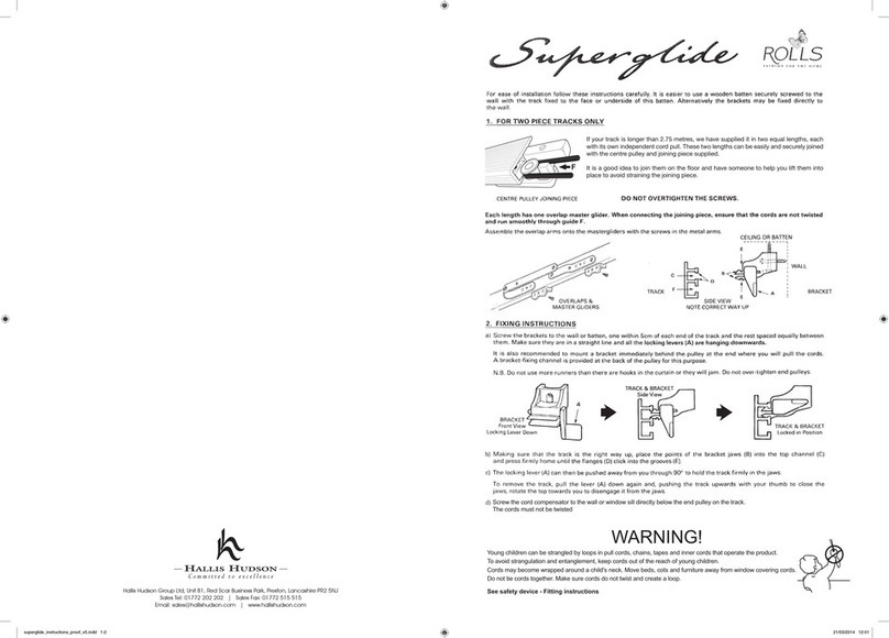
Hallis Hudson Rolls Super glide instructions

Hallis Hudson

Hallis Hudson Rolls Super glide instructions

Jysk ROGEN manual

Jysk

Jysk ROGEN manual

SOMFY 1241752 instructions

SOMFY

SOMFY 1241752 instructions

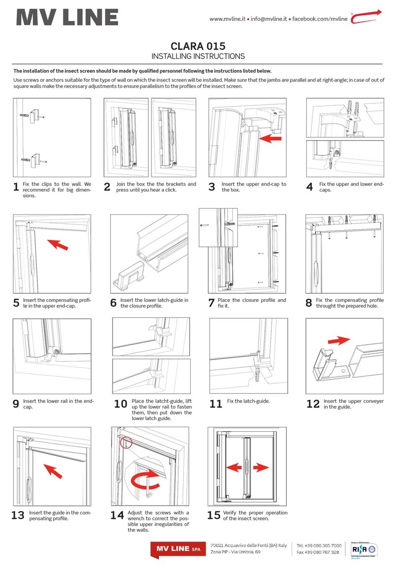
MV LINE CLARA 015 Installing instructions

MV LINE

MV LINE CLARA 015 Installing instructions

Project Source CDLF2342W quick start guide

Project Source

Project Source CDLF2342W quick start guide

Current E-WAND Installation manual and user's guide

Current

Current E-WAND Installation manual and user's guide

weinor VertiTex ZipR Maintenance Instructions and Directions for use for the end user

weinor

weinor VertiTex ZipR Maintenance Instructions and Directions for use for the end user

Roto ZAR M R4/R7 Mounting instructions

Roto

Roto ZAR M R4/R7 Mounting instructions

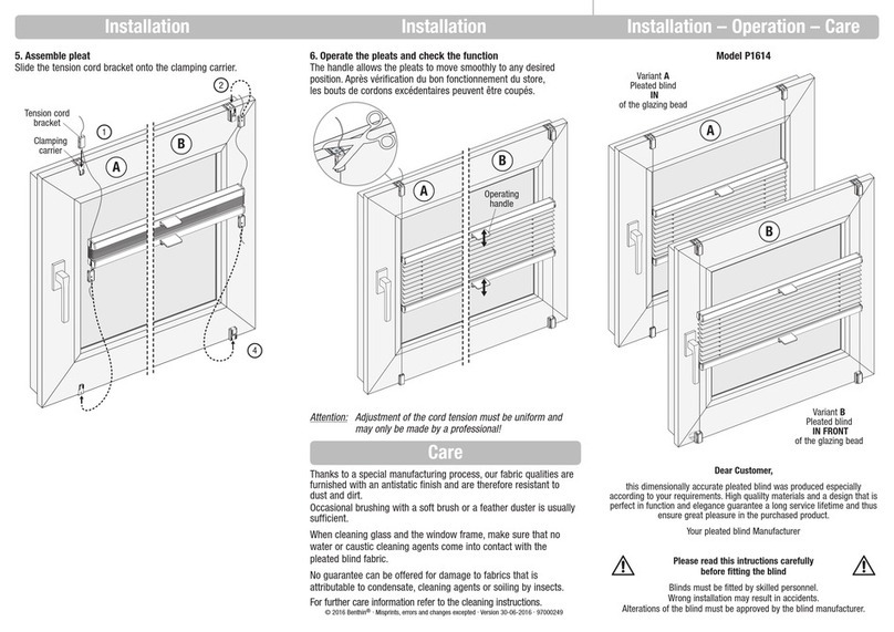
Benthin P1614 quick start guide

Benthin

Benthin P1614 quick start guide

MDT KNX Smart 55 BE-JTA5504.01 Technical manual

MDT

MDT KNX Smart 55 BE-JTA5504.01 Technical manual

Victoria M SYSTEM VS 1 Original instructions

Victoria M

Victoria M SYSTEM VS 1 Original instructions

SOMFY Movelite WT Series instructions

SOMFY

SOMFY Movelite WT Series instructions

IKEA ENJE manual

IKEA

IKEA ENJE manual

manuals.online logo
manuals.online logoBrands
  • About & Mission
  • Contact us
  • Privacy Policy
  • Terms and Conditions

Copyright 2025 Manuals.Online. All Rights Reserved.

Loggia®Handleiding - Installatie twee symmetrisch of simultaan schuivende panelen
Notice de montage - Installation de deux panneaux coulissants symétriques ou simultanés
Montageanleitung - Montage von zwei symmetrische oder simultane Schiebeläden
Manual - Installation of two symmetrically or simultaneously sliding panels
Loggia®
2
RENSON®LOGGIA®
Please read this manual carefully before you
start. The installation of two symmetrically
sliding Loggia®panels must be performed by
a professional.
Overview of tools required:
• Hand saw
• Cleaning equipment
• (Electric) screwdriver
• Drill
• Spirit level
• Fixation materials
• M8 spanner
• Allen keys
RENSON®reserves the right to make tech-
nical changes to its products without prior
notice.
RENSON®LOGGIA®
Veuillez lire attentivement ce manuel avant
de commencer l’installation. L’installation
de deux panneaux coulissants symétriques
Loggia®doit être réalisée par un profession-
nel.
Liste des outils nécessaires :
• Scie à main
• Matériel de nettoyage
• Visseuse / tournevis
• Perceuse
• Niveau
• Matériel de fixation
• Clé à molette M8
• Clés Allen / clés hexagonales
RENSON®se réserve le droit d’apporter des
modifications techniques à ses produits sans
avis préalable.
RENSON®LOGGIA®
Lesen Sie diese Anleitung sorgfältig durch,
bevor Sie beginnen. Die Anbringung von
zwei symmetrische Loggia®Schiebeläden
muss von einem Fachmann durchgeführt
werden.
Übersicht der benötigten Werkzeuge:
• Handsäge
• Reinigungsmaterial
• Schraubmaschine/Schraubendreher
• Bohrmaschine
• Wasserwaage
• Montagezubehör
• Schraubenschlüssel M8
• Inbusschlüssel/Sechskantschlüssel
RENSON®behält sich das Recht vor, ohne
vorherige Ankündigung technische Änderun-
gen an seinen Produkten vorzunehmen.
RENSON®LOGGIA®
Lees deze handleiding eerst aandachtig eer u
van start gaat. Het plaatsen van twee symme-
trisch schuivende Loggia®panelen dient te
gebeuren door een vakman.
Overzicht benodigde gereedschappen:
• Handzaag
• Reinigingsmateriaal
• Schroefmachine / schroevendraaier
• Boormachine
• Waterpas
• Bevestigingsmateriaal
• Moersleutel M8
• Inbussleutels/zeskantsleutels
RENSON®behoudt zich het recht voor om
zonder voorafgaande kennisgeving techni-
sche wijzigingen aan haar producten aan te
brengen.
Loggia®
3
TABLE OF CONTENTS
1. Parts overview 4
2. Sawing the profiles 6
3. Fitting the roller assemblies and
associated fittings 8
3.1 Right-hand panel 8
3.2 Left-hand panel 12
4. Upper rail installation options 16
4.1 Installation using wall mounting
profile 16
4.2 Installing the upper rail on the
ceiling 16
4.3 Installation with motor 18
5. Lower rail installation options 20
5.1 Fitting the L-profile 20
5.2 Fitting the Flexguide Plus 20
5.3 Fitting the U-profile 22
6. Fitting the Flexguides in the Loggia
frame (optional) 24
7. Fitting the carrier and belt tensioner 26
8. Positioning the panel on the lower rail 28
8.1 Flexguide Plus + Flexguide rail
option 28
8.2 Flexguide Long + L-profile option 28
8.3 Caps + L-profile option 28
8.4 Caps in U-profile option 28
9. Hanging the panels 30
9.1 Hanging the right-hand panel 30
9.2 Hanging the left-hand panel 32
10. Determining the belt length 34
11. Hanging the belt 36
11.1 Standard installation with belt 36
11.2 Installation of the belt with a
motor 36
12. Aligning the panels 38
13. Tensioning the belt 40
14. Installation of the motor 42
15. Fitting the cover (optional) 44
15.1 Fitting the cover 44
15.2 Fitting the aluminium end caps
(optional) 44
15.3 Fitting the plastic end caps
(optional) 44
16. Final checks 46
INHALTSVERZEICHNIS
1. Übersicht Teile 4
2. Sägen der Profile 6
3. Anbringen der Rollsysteme und der
dazugehörigen Komponenten 8
3.1 Laden rechts 8
3.2 Laden links 12
4. Montagemöglichkeiten der oberen
Schiene 16
4.1 Montage mit Wandmontageprofil 16
4.2 Montage der oberen Schiene an
der Decke 16
4.3 Montage mit Motor 18
5. Montagemöglichkeiten der unteren
Schiene 20
5.1 Anbringen des L-Profils 20
5.2 Anbringen des Flexguide Plus 20
5.3 Anbringen des U-Profils 22
6. Flexguide in den Loggia-Rahmen
montieren (Option) 24
7. Platzieren von Mitnehmer und
Riemenspanner 26
8. Positionierung des Ladens auf der
unteren Schiene 28
8.1 Option Flexguide Plus +
Flexguide-Schiene 28
8.2 Option Flexguide Lang + L-Profil 28
8.3 Option Kappen + L-Profil 28
8.4 Option Kappen in U-Profil 28
9. Aufhängen der Läden 30
9.1 Aufhängen des rechten Ladens 30
9.2 Aufhängen des linken Ladens 32
10. Riemenlänge bestimmen 34
11. Aufhängen des Riemens 36
11.1 Standardmontage des Riemen 36
11.2 Montage des Riemen mit einem
Motor 36
12. Ausrichtung der Läden 38
13. Spannen des Riemens 40
14. Motoreinbau 42
15. Anbringen der Abdeckkappe (Option) 44
15.1 Anbringen der Abdeckkappe 44
15.2 Anbringen der Aluminium-
Endkappen (Option) 44
15.3 Anbringen der Endkappen aus
Kunststoff (Option) 44
16. Kontrolle 46
TABLE DES MATIERES
1. Liste des composants 4
2. Découpe des profils 6
3. Pose des chariots et garnitures afférentes 8
3.1 Panneau droit 8
3.2 Panneau gauche 12
4. Possibilités de montage du rail
supérieur 16
4.1 Montage avec profil de fixation
murale 16
4.2 Montage du rail supérieur au
plafond 16
4.3 Montage avec moteur 18
5. Possibilités de montage du rail inférieur 20
5.1 Pose du profil en L 20
5.2 Pose du Flexguide Plus 20
5.3 Pose du profil en U 22
6. Montage du Flexguide dans le cadre
Loggia (option) 24
7. Pose du guide simultane et du tendeur
de courroie 26
8. Positionnement du panneau sur le rail
inférieur 28
8.1 Option Flexguide Plus + rail
Flexguide 28
8.2 Option Flexguide Long + profil
en L 28
8.3 Option embouts + profilen L 28
8.4 Option embouts dans profil en U 28
9. Suspension des panneaux 30
9.1 Suspension du panneau droit 30
9.2 Suspension du panneau gauche 32
10. Déterminer la longueur de la courroie 34
11. Suspension de la courroie 36
11.1 Placement standard de la
courroie 36
11.2 Placement de la courroie avec
moteur 36
12. Alignement des panneaux 38
13. Tension de la courroie 40
14. Installation du moteur 42
15. Pose du profil de finition (en option) 44
15.1 Pose du profil de finition 44
15.2 Pose des embouts en aluminium
(option) 44
15.3 Pose des embouts en synthétique
(option) 44
16. Contrôle 46
INHOUDSTAFEL
1. Overzicht onderdelen 4
2. Verzagen van de profielen 6
3. Plaatsen van rolstelsels en bijhorende
garnituren 8
3.1 Paneel rechts 8
3.2 Paneel links 12
4. Montagemogelijkheden van de
bovenrail 16
4.1 Montage met
muurbevestigingsprofiel 16
4.2 Montage van de bovenrail aan
het plafond 16
4.3 Montage motor 18
5. Montagemogelijkheden van de
onderrail 20
5.1 Plaatsen van het L-profiel 20
5.2 Plaatsen van de Flexguide Plus 20
5.3 Plaatsen van het U-profiel 22
6. Flexguide monteren in het Loggiakader
(optie) 24
7. Plaatsen van de meenemer en
riemspanner 26
8. Paneel positioneren op onderrail 28
8.1 Optie Flexguide Plus + Flexguide
rail 28
8.2 Optie Flexguide Lang + L-profiel 28
8.3 Optie dopjes + L-profiel 28
8.4 Optie dopjes in U-profiel 28
9. Ophangen van de panelen 30
9.1 Ophangen van het rechterpaneel 30
9.2 Ophangen van het linkerpaneel 32
10. Riemlengte bepalen 34
11. Ophangen van de riem 36
11.1 Standaard plaatsing van de riem 36
11.2 Plaatsing van de riem bij motor 36
12. Uitlijnen van de panelen 38
13. Opspannen van de riem 40
14. Installatie motor 42
15. Plaatsen van de afdekkap (optie) 44
15.1 Plaatsen van de afdekkap 44
15.2 Plaatsen van de aluminium
eindkappen (optie) 44
15.3 Plaatsen van de
kunststofeindkappen (optie) 44
16. Controle 46
Loggia®
4
1. PARTS OVERVIEW
1 Wall mounting profile (optional)
2 Upper rail
3 Plastic end cap (optional)
4 Aluminium cover plate (optional)
5 Aluminium cover (optional)
6 Loggia panel (left)
7 Loggia panel (right)
8 Reversing wheel
9 Belt
10 Belt tensioner
11 Bracket for cover (optional)
12 Roller assembly
13 Carrier
14 Tensioner for reversing wheel
15 Adjustable stopper
16 Flexguide Plus (optional)
17 Flexguide Long (optional)
18 Plastic cap for lower rail
19 L-shaped lower rail
20 Flexguide Plus lower rail (optional)
21 U-shaped lower rail (optional)
All optional elements are shown in light grey
on the drawing below.
1. ÜBERSICHT TEILE
1 Wandmontageprofil (Option)
2 Obere Schiene
3 Endkappe aus Kunststoff (Option)
4 Abdeckplatte aus Aluminium (Option)
5 Abdeckkappe aus Aluminium (Option)
6 Loggia-Laden links
7 Loggia-Laden rechts
8 Umlenkrad
9 Riemen
10 Riemenspanner
11 Befestigungswinkel für Abdeckkappe
(optional)
12 Rollensystem
13 Mitnehmer
14 Spannvorrichtung Umlenkrad
15 Einstellbarer Anschlag
16 Flexguide Plus (Option)
17 Flexguide Lang (Option)
18 Kunststoffkappe für Bodenführung
19 Bodenführung L
20 Bodenführung Flexguide Plus (Option)
21 Bodenführung U (Option)
Alle Optionen sind in der folgenden Zeich-
nung hellgrau dargestellt.
1. LISTE DES
COMPOSANTS
1 Profil de fixation murale (option)
2 Rail supérieur
3 Embout en synthétique (option)
4 Embout en aluminium (option)
5 Profil de finition en aluminium (option)
6 Panneau Loggia gauche
7 Panneau Loggia droit
8 Roue d’inversion
9 Courroie
10 Tendeur de courroie
11 Equerre de montage pour profil de
finition (option)
12 Chariot
13 Guide simultane
14 Tendeur pour rou d’inversion
15 Arrêt réglable
16 Flexguide Plus (option)
17 Flexguide Long (option)
18 Embout en synthétique pour le guide
inférieur
19 Guide inférieur en L
20 Guide inférieur Flexguide Plus (option)
21 Guide inférieur en U (option)
Toutes les options sont représentées en gris
clair sur le dessin ci-dessous.
1. OVERZICHT
ONDERDELEN
1 Muurbevestigingsprofiel (optie)
2 Bovenrail
3 Kunststof eindkap (optie)
4 Aluminium afdekplaatje (optie)
5 Aluminium afdekkap (optie)
6 Loggiapaneel links
7 Loggiapaneel rechts
8 Omkeerwiel
9 Riem
10 Riem spanner
11 Montagebeugel voor afdekkap (optie)
12 Rolstelsel
13 Meenemer
14 Opspaninrichting omkeerwiel
15 Regelbare stopper
16 Flexguide Plus (optie)
17 Flexguide Lang (optie)
18 Kunststof dopje voor ondergeleiding
19 Ondergeleiding L
20 Ondergeleiding Flexguide Plus (optie)
21 Ondergeleiding U (optie)
Alle opties worden in het lichtgrijs aangeduid
op onderstaande tekening.
Loggia®
5
11 10
13
14
12
1
2
3
4
5
7
6
8
9
15
17
16
20
19
21
18
Loggia®
6
2. SAWING THE PROFILES
• The profiles are delivered in standard
lengths of 3 or 6 metres. Saw the wall
mounting profile (optional), the lower rail,
the upper rail and the cover (optional) to
the required length. A
• Clean the upper and lower rails before
fitting any components. B
2. SÄGEN DER PROFILE
• Die Profile werden in einer Lagerlänge
von 3 oder 6 Metern geliefert. Sägen Sie
das Wandmontageprofil (Option), die
untere Schiene, die obere Schiene und die
Abdeckkappe (Option) auf die gewünschte
Länge. A
• Reinigen Sie die obere und untere Schiene,
bevor Sie die Komponenten montieren. B
2. DÉCOUPE DES PROFILS
• Les profils sont livrés dans une longueur de
3 ou 6 mètres. Découpez le profil de fixa-
tion murale (option), le rail inférieur, le rail
supérieur et le profil de finition (option) à la
longueur souhaitée. A
• Nettoyez le rail supérieur et le rail inférieur
avant de monter les composants. B
2. VERZAGEN VAN DE
PROFIELEN
• De profielen worden geleverd op een
stocklengte van 3 of 6 meter. Verzaag het
muurbevestigingsprofiel (optie), de onder-
rail, de bovenrail en de afdekkap (optie)
tot de gewenste lengte. A
• Reinig de boven- en onderrail voordat u de
componenten monteert. B
Loggia®
7
OPTION
A B
Loggia®
8
3. FITTING THE ROLLER
ASSEMBLIES AND
ASSOCIATED FITTINGS
• Remove the covers from the reversing
wheels using a 2.5 mm Allen key. A
3.1 Right-hand panel
• Overview B
• Slide the adjustable stopper into the upper
chamber of the upper rail and place it at
the position where the panel should stop.
C
Careful! Make sure the clamp on the adjust-
able stopper is positioned to the right!
3. ANBRINGEN DER
ROLLSYSTEME UND
DER DAZUGEHÖRIGEN
KOMPONENTEN
• Entfernen Sie die Abdeckkappen der
Umlenkräder mit einem 2,5-mm-Inbus-
schlüssel. A
3.1 Laden rechts
• Übersicht B
• Schieben Sie den verstellbaren Anschlag
in die oberste Kammer der oberen Schiene
und platzieren Sie ihn dort, wo der Laden
anschlagen soll. C
Achtung! Stellen Sie sicher, dass die
Klemme am verstellbaren Anschlag rechts
positioniert ist!
3. POSE DES CHARIOTS
ET GARNITURES
AFFÉRENTES
• Démontez les caches des roues d’inversion
à l’aide d’une clé Allen de 2,5 mm. A
3.1 Panneau droit
• Aperçu B
• Faites glisser l’arrêt réglable dans la
chambre supérieure du rail supérieur et
placez-le à l’endroit où le panneau doit
s’arrêter. C
Attention! Veillez à ce que l’attache sur
l’arrêt réglable soit positionnée à droite!
3. PLAATSEN VAN
ROLSTELSELS EN
BIJHORENDE
GARNITUREN
• Demonteer de afdekkappen van de
omkeerwielen met inbussleutel 2,5 mm.
A
3.1 Paneel rechts
• Overzicht B
• Schuif de regelbare stopper in de boven-
ste kamer van de bovenrail en plaats hem
waar het paneel moet stoppen. C
Opgelet! Zorg dat de klem op de regelbare
stopper rechts gepositioneerd is!
Loggia®
9
A
C
B
Loggia®
10
3. Fitting the roller assemblies
and associated fittings
(continued1)
3.1 Right-hand panel (continued)
• Slide 2 roller assemblies into the upper
rail. A
• Slide 1 reversing wheel into the upper rail.
B
• Position the reversing wheel at 10 mm from
the end of the upper rail. Fasten the revers-
ing wheel using the 4 hex cap screws
(using a 2.5 mm Allen key). C
Careful! Make sure all parts are fitted in the
right direction!
3. Anbringen der Rollsysteme
und der dazugehörigen
Komponenten (Fortsetzung1)
3.1 Laden rechts (Fortsetzung)
• Schieben Sie 2 Rollensysteme in die obere
Schiene. A
• Schieben Sie 1 Umlenkrad in die obere
Schiene. B
• Positionieren Sie das Umlenkrad 10 mm
vom äußeren Ende der oberen Schiene
entfernt. Schrauben Sie das Umlenkrad mit
4 Inbusschrauben (mit 2,5-mm-Inbusschlüs-
sel) fest. C
Achtung! Alle Teile in die richtige Richtung
montieren!
3. Pose des chariots et
garnitures afférentes (suite1)
3.1 Panneau droit (suite)
• Faites glisser 2 chariots dans le rail supé-
rieur. A
• Faites glisser 1 roue d’inversion dans le rail
supérieur. B
• Placez la roue d’inversion à 10 mm de
l’extrémité du rail supérieur. Vissez la roue
d’inversion avec les 4 vis à tête hexago-
nale (avec clé hexagonale de 2,5 mm). C
Attention! Montez tous les éléments dans
le bon sens!
3. Plaatsen van rolstelsels
en bijhorende garnituren
(vervolg1)
3.1 Paneel rechts (vervolg)
• Schuif 2 rolstelsels in de bovenrail. A
• Schuif 1 omkeerwiel in de bovenrail. B
• Positioneer het omkeerwiel op 10 mm van
het uiteinde van de bovenrail. Schroef het
omkeerwiel vast met de 4 inbusschroefjes
(met zeskantsleutel 2,5 mm). C
Opgelet! Monteer alle onderdelen in de
juiste richting!